

Page 1
1
761
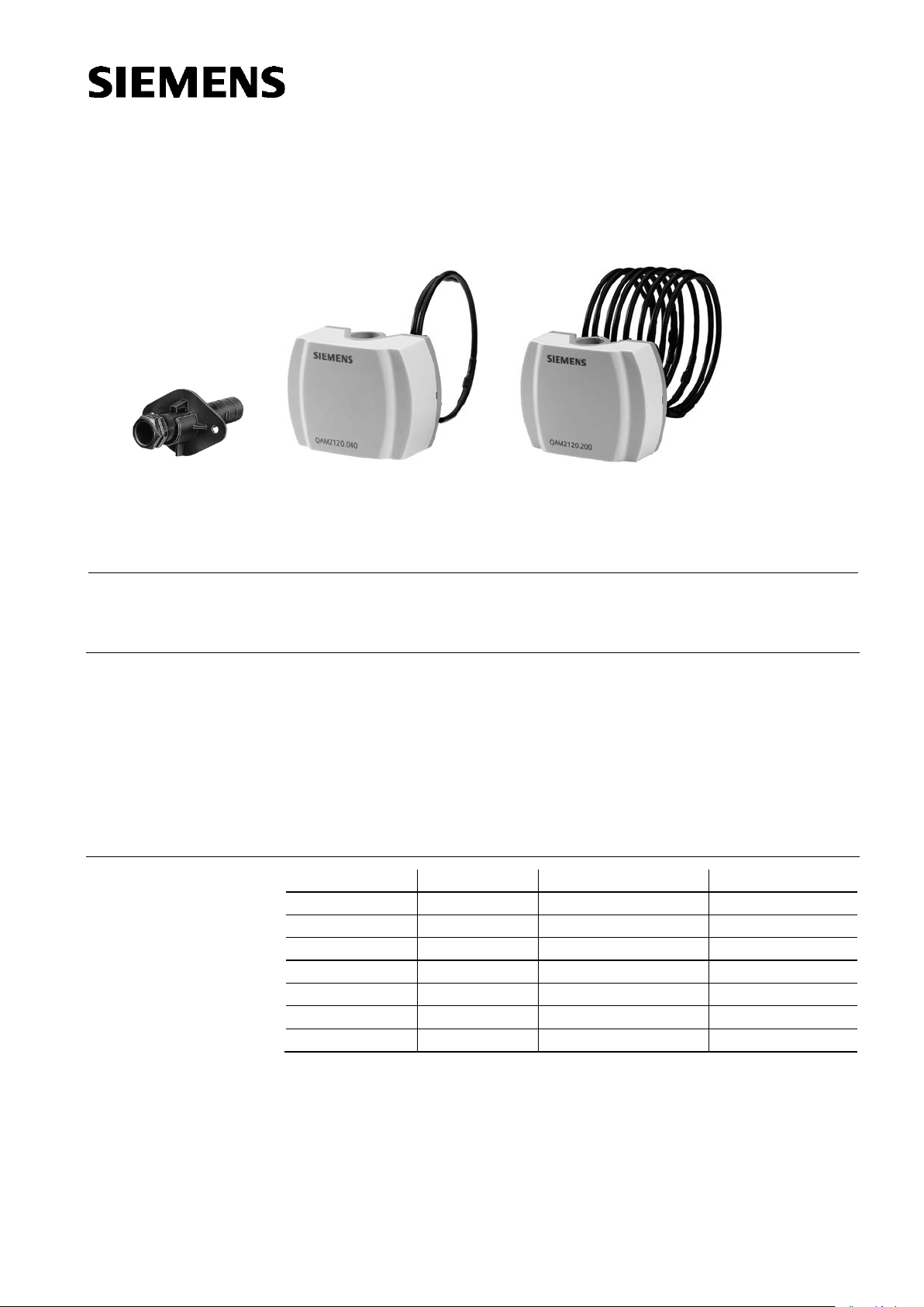
Mountin g flange AQM63.0
QAM2110.040, QAM2120.040
Symaro™
Duct Temperature Sensors
QAM21...
Type reference
Probe length
Mounting clamps
Sensing element
QAM2110.040
0,4 m
no
Pt 100
QAM2112.040
0,4 m
no
Pt 1000
QAM2112.200
2,0 m
4 pcs.
Pt 1000
QAM2120.040
0,4 m
no
LG-Ni 1000
QAM2120.200
2,0 m
4 pcs.
LG-Ni 1000
QAM2120.600
6,0 m
6 pcs
LG-Ni 1000
QAM2130.040
0,4 m
no
NTC 10k
1761P02
1761P03
1761P01
Use
Type summary
QAM2120.200, QAM2120.600
Passive sensors for acquiring the air temperature in air ducts.
The duct temperature sensors are for use in ventilation and air conditioning plants as:
• Supply or extract air temperature sensors
• Limit sensors, e.g. for minimum limitation of the supply air temperature
• Reference sensors, e.g. for shifting the room temperature as a function of the out-
side temperature
• Measuring sensors, e.g. for measured value indication or for connection to a building
automation and control system
CE1N1761en
2014-07-30
Building Technologies
Page 2
(6 pieces)
Monting flange
AQM63.0
Ordering and delivery
−40 −30 −20 −10 0 10 20 30 40 50 60 70 80
1400
1200
1000
800
600
R
[Ω]
[°C]
1771D01
−50
ϑ
−50−40−30−
20
−
10 0
10 20 30 40 50 60 70
2.0
1.0
0.0
−
1.0
−2.0
∆ϑ
[K]
[°C]
1771D02
ϑ
80
−40 −30 −20 −10 0 10 20 30 40 50 60 70 80
140
120
100
80
60
R
[Ω]
[°C]
1811D05
−50
ϑ
−50−40−30−
20
−
10 0 10 20 30 40 50 60 70 80
0.8
0.4
0.0
−
0.4
∆ϑ
[K]
ϑ
1811D06
[°C]
−
0.8
Accessories
(Spare parts)
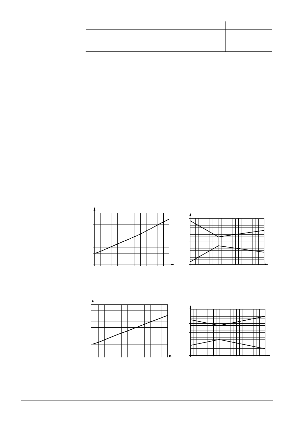
Sensing elements
LG-Ni 1000
Pt 100 (class B)
Equipment combinations
Function
Name Type reference
Capillary tube clamb for the QAM2120.200 and QAM2120.600
AQM63.3
When ordering, please give name and type reference, e.g.:
Duct temperature sensor QAM2120.040
The sensor is supplied complete with mounting flange AQM63.0 and, if required,
mounting clamps AQM63.3.
All systems or devices capable of acquiring and handling the sensor’s passive output
signal.
The sensor acquires the air temperature via its sensing element whose resistance
changes as a function of the temperature. The signal is delivered to a suitable controller
for further handling.
Characteristic: Accuracy:
Characteristic: Accuracy:
2/6
Siemens Duct temperature sensors QAM21... CE1N1761en
Building Technologies 2014-07-30
Page 3

Characteristic: Accuracy:
−40−30−20−
10 0 10 20 30 40 50 60 70 80
1400
1200
1000
800
600
R
[Ω]
[°C]
1761D01
−
50
ϑ
−50−40−30−
20
−
10 0 10 20 30 40 50 60 70 80
0.8
0.4
0.0
−
0.4
∆ϑ
[K]
ϑ
1761D02
[°C]
−
0.8
1000
10000
100000
1000000
-40
-30
-20 -10 0
10 20 30
40 50 60 70
80
[°C]
ϑ
R
[Ω]
1811D09
∆ϑ
[K]
1811D08
-1.20
-1.00
-0.80
-0.60
-0.40
-0.20
0.00
0.20
0.40
0.60
0.80
1.00
1.20
-40 -30 -20 -10 0 10 20 30 40 50 60 70 80
[°C]
ϑ
Pt 1000 (class B)
NTC 10k
Legend
Mechanical design
Characteristic: Accuracy:
R Resistance value in Ohm
ϑ Temperature in degrees Celsius
∆ϑ Temperature differential in Kelvin
The duct temperature sensor consists of the following components:
• Two-sectional plastic housing comprised of base with connection terminals and removable cover (snap-on design)
• Fully active, flexible probe with sensing element which acquires the average temperature
The connection terminals can be accessed after removing the cover. Cable entry is
made via a grommet which, if required, can be replaced by a cable entry gland M16
(IP 54).
After fitting the mounting flange, the sensor can be installed in 6 different immersion
positions so that the sensor housing is always located outside the insulation for layers
up to 70 mm. The probe with a length of 2 or 6 m is to be fitted across the air duct with
the help of the mounting clamps supplied with the sensor.
Siemens Duct temperature sensors QAM21... CE1N1761en
Building Technologies 2014-07-30
3/6
Page 4

Mounting notes
1761Z03
max. 70 mm
min. 200 mm
2
1
1761Z05
1761Z07
A
1761Z09
A
Mounting location
Mounting positions
Mounting examples
• For supply air temperature control: Downstream from the fan, if the fan is located
after the last air handling unit. Otherwise, after the last air handling unit with a minimum distance of 0.5 m
• For extract air temperature control: Always upstream of the extract air fan
• As a limit sensor for the supply air temperature: As close as possible to the air outlet
into the room
• For dew point control: Immediately after the spray trap of the air washer
Manually bend the probe so that it lies diagonally across the duct or in equally spaced
windings across the entire duct cross-section. The probe must not touch the duct wall.
The sensor is supplied complete with Mounting Instructions.
permitted: not permitted:
Disposal
The devices are considered electronics devices for disposal in terms of European Directive 2012/19/EU and may not be disposed of as domestic waste.
• Dispose of the device via the channels provided for this purpose.
• Comply with all local and currently applicable laws and regulations.
4/6
Siemens Duct temperature sensors QAM21... CE1N1761en
Building Technologies 2014-07-30
Page 5

Technical data
Operating range
−
−
Sensing element
refer to "Type summary“
Probe
Min. bending radius
refer to "Type summary“
10 mm
Time
30 s at 2
Dead time
<1 s
Measuring accuracy
refer to “Function"
Protection class
III according to EN 60730-1
Protection degree of housing
IP42 according to EN 60529
IP54 according to E
(not included as standard)
Screw terminals for
1 x 2.5 mm2 or 2 x 1.5 mm2
Cable entry
for 5.5...7.2 mm dia. cable
M 16 x 1.5 can be fitted
Perm. cable lengths
refer to Data Sheet of the relevant controller
Product standard
EN 60730
Automatic electrical controls for household and similar
use
UL UL 873,
Operation
Humidity (housing)
to IEC
class 3K5
–
5...95 % r. h.
Transport
to IEC
class 2K3
–
<
class 2M2
Probe
copper, polyolefine
Base
polycarbonate, RAL 7001 (silver-grey)
Cover
polycarbonate, RAL 7035 (light-grey)
Mounting flange
PA 66 (black)
Clamps
PA-GF 35 (black)
Packaging
corrugated cardboard
Incl. packaging
QAM2130.040
ca. 0,15 kg
ca. 0,15 kg
ca. 0,3 kg
ca. 0,15 kg
ca. 0,30 kg
ca. 0,53 kg
ca. 0,15 kg
B M
1761G01
Functional data
Degree of protection
Electrical connections
Directives and Standards
Environmental conditions
Materials and colors
Weight
Length
constant
With cable entry gland M 16 x 1.5
Grommet
Cable entry gland
Climatic conditions
Temperature (housing)
40...+ 80 °C for NTC type
50...+ 80 °C other types
m/s
N 60529
-1
http://ul.com/database
60721-3-3
40...+ 70 °C
Internal diagram
Climatic conditions
Temperature
Humidity
Mechanical conditions
QAM2110.040
QAM2112.040
QAM2112.200
QAM2120.040
QAM2120.200
QAM2120.600
60721-3-2
25...+ 70 °C
95 % r. h.
The internal diagram is identical for all types of duct temperature sensors covered by
this Data Sheet.
The connecting wires are interchangeable.
Siemens Duct temperature sensors QAM21... CE1N1761en
Building Technologies 2014-07-30
5/6
Page 6

Dimensions
2004 - 2014 Siemens Switzerland Ltd. Subject to change
Typ L1 L2
max. min.
QAM2130.040
QAM2110.040
400 97 37
400 97 37
QAM2120.040
QAM2112.040
QAM2112.200
QAM2120.200
QAM2120.600
400 97 37
400 97 37
2000 97 37
2000 97 37
6000 97 37
Drilling plan
Dimensions in mm
6/6
Siemens Duct temperature sensors QAM21... CE1N1761en
Building Technologies 2014-07-30
 Loading...