

Page 1
Modulating Control Valves
with Magnetic Actuators, Positioning Control and
Position Feedback for Domestic Water
MXG461B Series
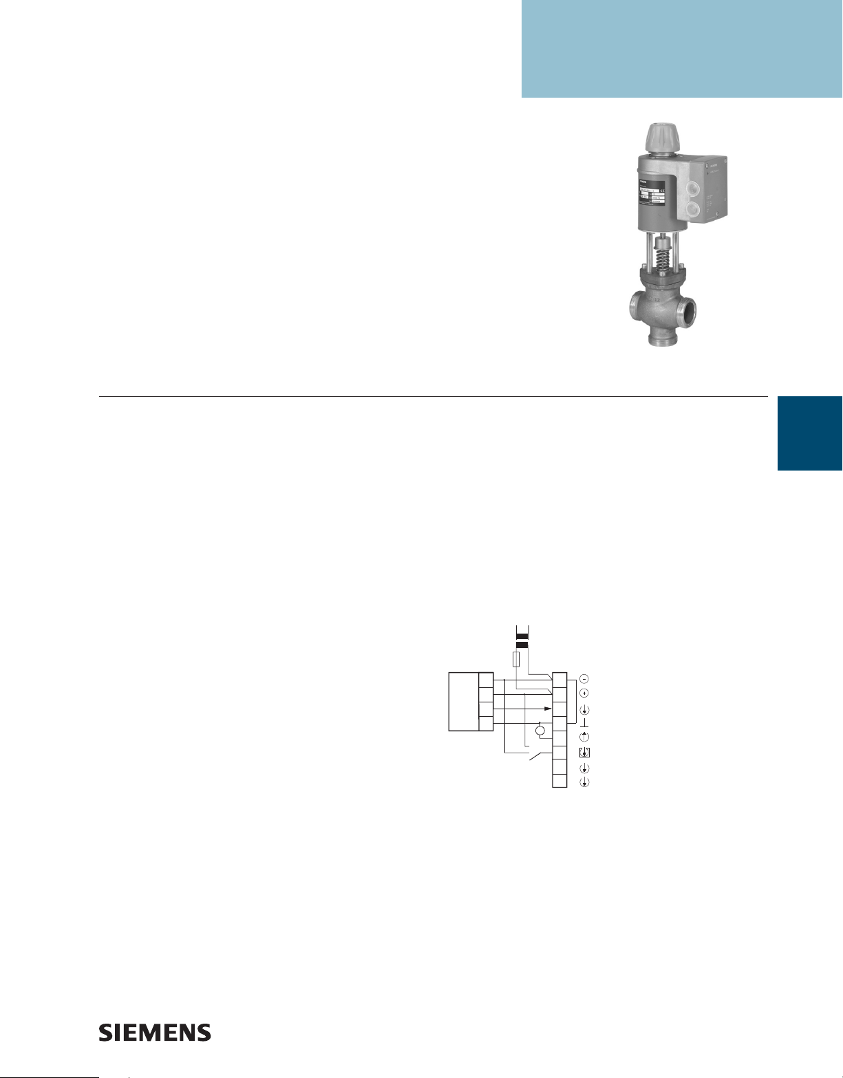
MXG461B Series Modulating Control Valve.
Description
The MXG461B Modulating Control Valve is a control valve
with magnetic actuator, for modulating control of domestic
water, cold water and hot water systems.
Features
• Fast positioning time (< 2 seconds)
• Selectable valve characteristic: Equal
percentage or linear
• Selectable control signal: 0/2 to 10 Vdc or
0/4 to 20 mA
• High resolution (>1000:1)
• High rangeability
• Wear-free inductive stroke measurement
• Spring return A
de-energized
• Positioning control and position
feedback signal
• Low-friction, heavy-duty and
maintenance-free
→
AB closed when
Applications
The MXG461B... Modulating Control Valves are throughport or mixing valves with magnetic actuators. The
actuator is equipped with an electronics module for
positioning control and position feedback. If the power is
off, the valve control path A
→
AB is closed.
The short positioning time, high resolution and high
rangeability make these valves ideal for modulating control
of domestic, hot and cold water systems.
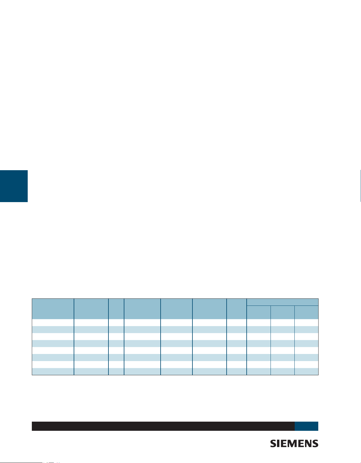
Wiring Diagram
Transformer
Controller
SSEN0346R1
F
G0
G
Y
M
U
G0
G
Y
M
U
Z
System neutral (SN)
System potential (SP)
0 to 10Vdc / 2 to 10Vdc
0 to 20 mA / 4 to 20 mA
Measuring neutral (= G0)
0 to 10Vdc / 2 to 10Vdc
0 to 20 mA / 4 to 20 mA
Override input
AC/DC 24 V Operating voltage
Control signal
Positioning feedback signal
A-229
Valves
www.usa.siemens.com/hvac
Page 2
Specications/Sizing
MXG461B Modulating Control Valve Specifications
A-230
Valves
Electrical
Low-voltage Use Only ..............................................Class 2 (SELV, PELV)
24 Vac
Operating Voltage........................................................24 Vac +20/-15%
Frequency ............................................................................ 45 to 65 Hz
Typical Power Consumption .................................................See Table 1
Standby ......................................................... <1 W (Valve Fully Closed)
Nominal Apparent Power..............................................See Sizing Table
Suitable Fuse .............................................................Slow, See Table 1
24 Vdc
Operating Voltage............................................................... 20 to 30 Vdc
Functional Data of Actuator
Input
Positioning Signal Y 0/2 to 10 Vdc or 0/4 to 20mA
Impedance
0/2 to 10Vdc ...............................................................100 kΩ//5nF
0/4 to 20 mA ................................................................240 Ω//5nF
Forced Control
Impedance ................................................................................ 22 kΩ
Closing the Valve (Z Connected to G0) .................. <1 Vac; <0.8 Vdc
Opening the Valve (Z Connected to G0) ..................> 6 Vac; >5 Vdc
No Function (Z Not Wired)....................... Positioning Signal Y Active
Output
Position Feedback Signal Voltage .................................... 0/2 to 10 Vdc;
Load Resistance > 500Ω
Current ..................................................................... 0/4 to 20 mA;
Load Resistance < 500Ω
Stroke Measurement ................................................................ Inductive
Nonlinearity ................................................................±3% of End Value
Functional Data of Valve
Nominal Pressure .......................................................ANSI 125 (PN 16)
Operating Pressure pemax1 .......................................... 232 psi (16 bar)
Pressure Differential Dpvmax ......................................See Sizing Table.
Leakage..................................................... A → AB Maximum 0.05% Cv
B → AB Depends on Application Data
(0.2% Cv)
Water Temperature2 ....................................... -4 to 248°F (-20 to 120°C)
Valve Characteristic3 .................Equal Percentage or Linear, Optimized
...................................................................Near the Closing Point
Resolution .......................................................................................1:1000
Type of Operation ..................................................................Modulating
Position De-energized ...................................................... A → AB Closed
Orientation ................................................................Upright to Horizontal
Positioning Time ................................................................... < 2 Seconds
Materials
Body ....................................................................................Red Bronze
Cover Flange ........................................................................Red Bronze
Seat/Inner Valve ..............................................................Stainless Steel
Packing
Normal Duty ....................................................................EPDM (O-ring)
Pipe Connections ................................... Screwed Fittings, Bronze/Brass
Electrical Connections
Cable Entries ............................................3 x M20 x1.5 or PG13.5/G1/2
Connection Terminals ......................Screw Terminals for 12 AWG Wires
Min. Cross-sectional Area4 .................................................. 18 ga. AWG
Max. Cable Length ................................................... Refer to Sizing Table.
Ambient Conditions
Temperature
Operation and Storage .................................23 to 113°F (-5 to 45°C)
Transport ..................................................-13 to 158°F (-25 to 70°C)
Humidity .............................................................................. 5 to 95% rh
Agency Approvals .......................................................... IP31 to IEC 529
Conforms to CE Requirements, UL 873,
Certied to Canadian Standard C22.2 No. 24, C-Tick N-474,
Par. 1, Section. 2.1.4 / Par. 3, Section 3, Fluid Group 2
Flow Characteristics ................................... Equal Percentage or Linear
Notes:
1
Tested at 1.5 x PN (24 bar), similar to DIN 3230-3
2
For medium temperatures <32°F (0°C), the Z366 stem heating
element is required.
3
Can be selected via DIP switch.
4
In case of strong vibrations, use high-ex stranded wires.
PED 97/23/EC: Pressure-carrying Parts,
Sizing
Max. Close-off
Valve
Part No.
MXG461B15-0.6 1/2 0.7 145 33 15 3.15 130 215 360
MXG461B15-1.5 1/2 1.8 145 33 15 3.15 130 215 360
MXG461B15-3 1/2 3.5 145 33 15 3.15 130 215 360
MXG461B20-5 3/4 5.8 11 6 33 15 3.15 130 215 360
MXG461B25-8 1 9.3 102 33 15 3.15 130 215 360
MXG461B32-12 1-1/4 14 87 43 20 4 100 165 260
MXG461B40-20 1-1/2 23 87 43 20 4 100 165 260
MXG461B50-30 2 35 87 65 22 6.3 65 100 185
Size (in.)
Cv
Pressure
(psi)
Power for
Transformer
Sizing (VA)
Power
Consumption
(W)
Slow
Fuse
Accessories & Service Kits
www.usa.siemens.com/hvac
Wire Gauge (AWG)
16 14 12
A-257
Page 3

MXG461B Modulating Control Valve
Product Ordering
Valve Size (in)
1/2 0.7 MXG461B15-0.6
1/2 1.8 MXG461B15-1.5
1/2 3.5 MXG461B15-3
3/4 5.8 MXG461B20-5
1 9.3 MXG461B25-8
1-1/4 14 MXG461B32-12
1-1/2 23 MXG461B40-20
2 35 MXG461B50-30
Ordering Notes:
• When placing an order, specify the quantity, product number
and description.
Example: 1 MXG461B15-0.6 valve and 1 Z366 stem heater
• The valve body and magnetic actuator assemblies cannot be
separated.
• The screwed ttings and gaskets are supplied with
these valves.
Cv Part No.
A-231
Valves
www.usa.siemens.com/hvac
Page 4

Dimensions and Weights
SVAL0233R1
min.
3.94
(100)
1.97
(50)
F
min.
3.94
(100)
A-232
Valves
H
L2
G
Dimensions shown in inches (mm).
Line Size
Part No.
MXG461B15-0.6 1/2 (15) 1/2 G1B 3.15 (80) 1.67 (42.5) 1.97 (50) 13.4 (340) 3.15 (80) 4.53 (115) 15.65 (7.1)
MXG461B15-1.5 1/2 (15) 1/2 G1B 3.15 (80) 1.67 (42.5) 1.97 (50) 13.4 (340) 3.15 (80) 4.53 (115) 16.09 (7.3)
MXG461B15-3 1/2 (15) 1/2 G1B 3.15 (80) 1.67 (42.5) 1.97 (50) 13.4 (340) 3.15 (80) 4.53 (115) 16.09 (7.3)
MXG461B20-5 3/4 (20) 3/4 G1-1/4B 3.74 (95) 2.07 (52.5) 2.36 (60) 13.3 (339) 3.15 (80) 4.53 (115) 16.97 (7.7)
MXG461B25-8 1 (25) 1 G1-1/2B 4.33 (110) 2.22 (56.5) 2.52 (64) 13.6 (346) 3.15 (80) 4.53 (115) 18.73 (8.5)
MXG461B32-12 1-1/4 (32) 1-1/4 G2B 4.92 (125) 2.66 (67.5) 2.95 (75) 15.12 (384) 3.94 (100) 4.92 (125) 28.22 (12.8)
MXG461B40-20 1-1/2 (40) 1-1/2 G2-1/4B 5.51 (140) 3.17 (80.5) 3.66 (93) 15.79 (401) 3.94 (100) 4.92 (125) 32.19 (14.6)
MXG461B50-30 2 (50) 2 G2-3/4B 6.69 (170) 3.68 (93.5) 4.2 (108) 17.58 (449) 3.94 (100) 4.92 (125) 41.00 (18.6)
Table expressed in inches (mm).
In. (mm) RP
G
(in) L1 L2 L3 H E F
E
AAB
B
L1
Rp
L3 *
Weight
lb. (kg)
Table Notes:
• A: External thread G...B to ISO228/1
• DN: Internal thread Rp to ISO7/1
• Fittings to ISO 49/DIN 2950 (supplied complete with ange gaskets)
www.usa.siemens.com/hvac
 Loading...