

Page 1
714
4
ACVATIX
TM
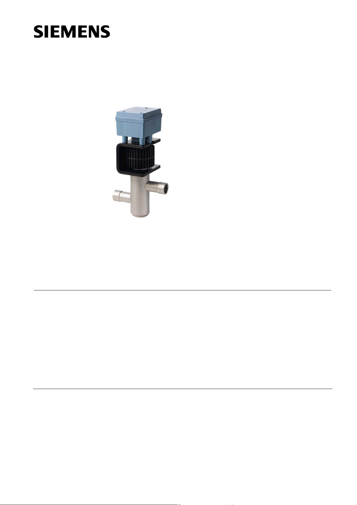
Modulating refrigerant
valves with magnetic
actuator, PS45
Hermetically sealed, for safety refrigerants
MVL661..-..
Use
CE2N4714en
30.05.2011
• One valve type for expansion, hot-gas and suction throttle applications
• Hermetically sealed towards outside
• Selectable standard interface DC 0/2...10 V or DC 0/4...20 mA
• High resolution and control accuracy
• Precise positioning control and position feedback signal
• Short positioning time (< 1 s)
• Closed when deenergized
• Robust and maintenance-free
• Five valve sizes with k
The MVL661..-.. refrigerant valve is designed for modulating control of refrigerant
circuits including chillers and heat pumps. It can be used in expansion, hot-gas and
suction throttle applications as well as with all commonly used safety refrigerants (R22,
R134a, R404A, R407C, R410A, R507, etc.) and R744 (CO
inflammable refrigerants.
values from 0.25 to 12 m³/h
vs
). Not suitable for
2
Building Technologies
Page 2
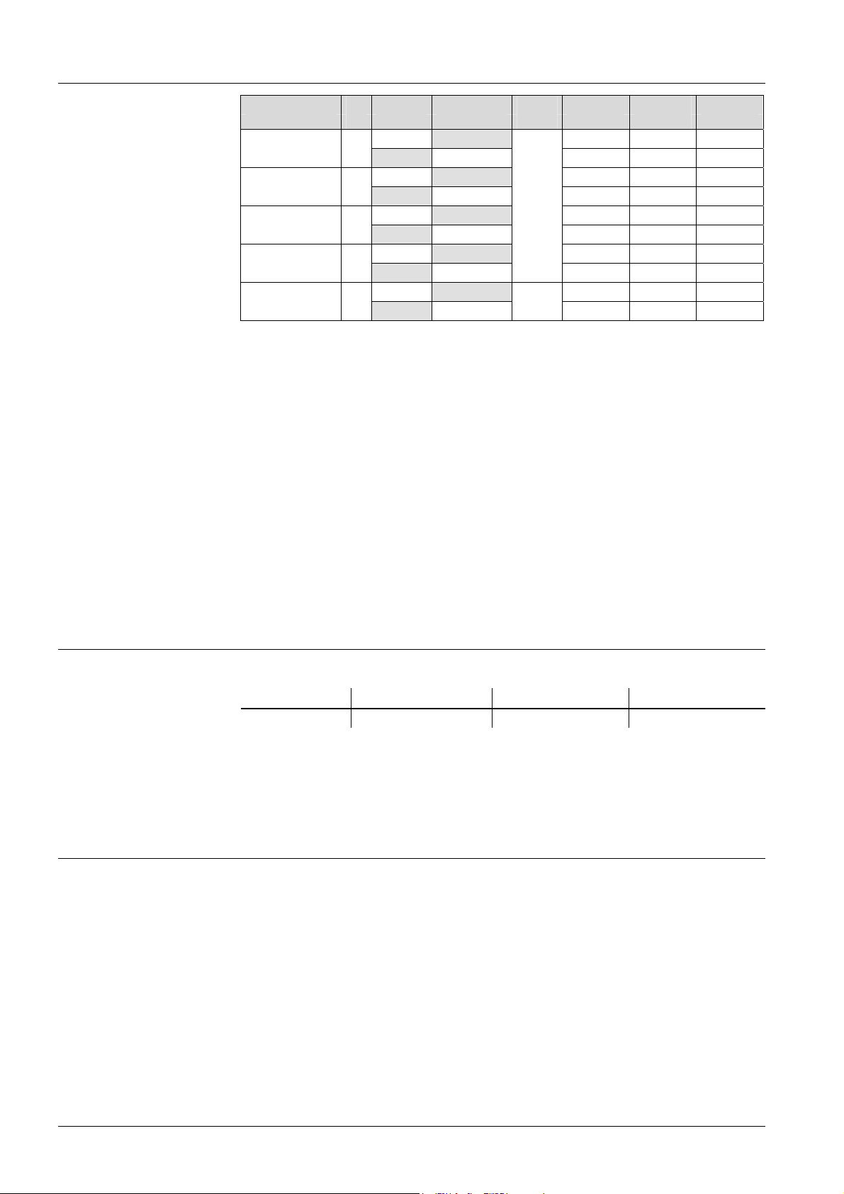
Type summary
Type reference DN kvs k
reduced
vs
1)
Δp
max
Q0 E Q0 H Q0 D
[m3/h] [m3/h] [MPa] [kW] [kW] [kW]
MVL661.15-0.4 15
MVL661.15-1.0 15
MVL661.20-2.5 20
MVL661.25-6.3 25
MVL661.32-12 32
1)
63% of kvs, refer to "kvs reduction" on page 4
2)
MVL661.32-12.0 is only approved for suction throttle applications
Nominal flow rate of refrigerant through the fully open valve (H
k
vs
0.40 47 9.2 1.7
0.25 29 5.7 1.0
1.0 117 23 4.2
0.63 74 14 2.6
2.5 293 57 10
2.5
1.6 187 37 6.6
6.3 737 144 26
4
12
8
0.2
468 92 17
2)
2)
) at a differential pressure of
100
2)
50
2)
33
100 kPa (1 bar) to VDI 2173
Q
E Refrigeration capacity in expansion applications
0
Q
H Refrigeration capacity in hot-gas bypass applications
0
D Refrigeration capacity in suction throttle applications and Δp = 0.5 bar
Q
0
With R407C at t0 = 0 °C, tc = 40 °C
Q
0
The pressure drop across evaporator and condenser is assumed to be 0.3 bar each, and 1.6 bar
upstream of the evaporator (e.g. spider).
The capacities specified are based on superheating by 6 K and subcooling by 2 K.
The refrigeration capacity for various refrigerants and operating conditions can be
calculated for the 3 types of application using the tables at the end of this data sheet.
For accurate valve sizing, we recommend the valve selection program "Refrigeration
VASP".
Ordering
Example:
Spare parts
Rev. no.
Functio
n / mechanical design
Features and benefits
Valve body and magnetic actuator form one integral unit and cannot be separated.
Product number Stock number Designation
MVL661.15-0.4 MVL661.15-0.4 Refrigerant valve 1
Quantity
If the valve’s electronics become faulty, the entire electronics housing must be replaced
by spare part ASR61, supplied complete with mounting instructions (74 319 0270 0).
See table on page 17.
• 4 selectable standard signals for setpoint and measured value
• DIP switch to reduce the k
value to 63% of the nominal value
vs
• Potentiometer for adjustment of minimum stroke for suction throttle applications
• Automatic stroke calibration
• Forced control input for “Valve closed” or “Valve fully open”
• LED for indicating the operating state
The MVL661..-.. can be driven by Siemens or third-party controllers that deliver
a DC 0/2...10 V or DC 0/4...20 mA output signal.
For optimum control performance, we recommend a 4-wire connection between
controller and valve. When operating on DC voltage, a 4-wire connection is mandatory!
The valve stroke is proportional to the control signal.
2/18
Siemens Modulating refrigerant valves with magnetic actuator, PS45 CE2N4714en
Building Technologies 30.05.2011
Page 3
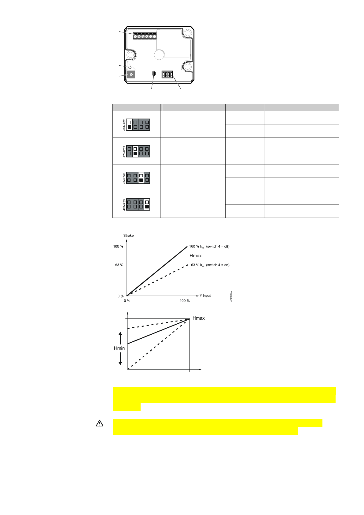
Operator controls and
indicators in the
electronics housing
1
G0 G Y UMZC
1 Connection terminals
2 LED for indication of operating state
3 Minimal stroke setting potentiometer Rv
4 Autocalibration
2
3
on
1234
5 DIL switches for mode control
Configuration of
DIL switches
-reduction
k
vs
Minimum stroke
setting
Caution
45
4716Z15
Switch Function ON / OFF Description
ON
1
ON
2
ON
3
ON
1)
Factory setting
Positioning signal Y
Positioning range Y and U
Position feedback U
Nominal flow rate k
4
vs
ON Current [mA]
1)
OFF Voltage [V]
ON DC 2…10 V, 4…20 mA
OFF DC 0…10 V, 0…20 mA
ON Current [mA]
OFF Voltage [V]
ON
OFF
For k
63%
100%
reduction (DIL switch 4 in
vs
1)
1)
position ON), the stroke is limited to
63% mechanical stroke. 63% of full
stroke then corresponds to an
input/output signal of 10 V.
If, in addition, the stroke is limited
to 80%, for example, the minimum
stroke is 0.63 x 0.8 = 0.50 of full
stroke.
100 %
80 %
Stroke
In the case of a suction throttle valve, it is
4716D01en
essential that a minimum stroke limit be
maintained to ensure compressor cooling
and efficient oil return. This can be
achieved with a reinjection valve, a bypass
line across the valve, or a guaranteed
minimum opening of the valve. The
0 %
0 % 100 %
Y-i np ut
minimum stroke can be defined via the
controller and control signal Y, or it can be
set directly with potentiometer Rv.
The factory setting is zero (mechanical stop in counterclockwise direction, CCW). The
minimum stroke can be set by turning the potentiometer clockwise (CW) to a maximum
of 80% kvs.
Do not under any circumstances use potentiometer Rv to limit the stroke on
expansion applications. It must be possible to close the valve fully.
1)
3/18
Siemens Modulating refrigerant valves with magnetic actuator, PS45 CE2N4714en
Building Technologies 30.05.2011
Page 4
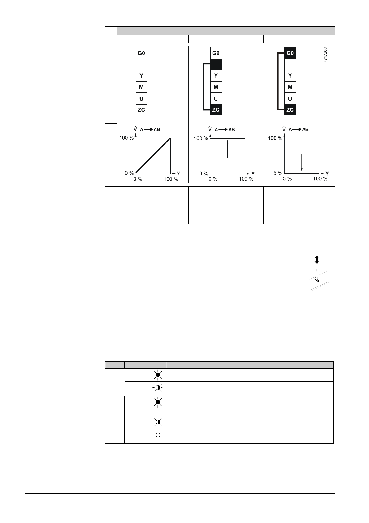
Forced control input ZC
No function Fully open Closed
ZC – Function
Signal priority
Calibration
When is a calibration
required?
Indication of operating
state
Connections Transfer
• ZC not connected
• Valve will follow the Y-signal
• Minimum stroke set-ting
function
with potentiometer Rv
possible
G
• ZC connected to G
• Valve will fully open control
path A AB
• ZC connected to G0
• Valve will close control path
GG
A AB
1. Forced control signal ZC
2. Signal input Y and/or minimum stroke setting with potentiometer Rv possible.
The printed circuit board of the MVL661..-.. has a slot to facilitate calibration.
01124
To calibrate, insert a screwdriver in the slot so that the contacts inside are
connected. As a result, the valve will first be fully closed and then fully
opened.
Calibration matches the electronics to the valve mechanism.
During calibration, the green LED flashes for about 10 seconds; refer to
"Indication of operating state" (page 4).
MVL661..-.. refrigerant valves are supplied fully calibrated.
Execute a calibration after replacing the electronics, when the red LED is lit or flashing
or when the valve is leaking (at seat).
LED Indication Function Remarks, troubleshooting
Green Lit
Flashing
Red Lit
Flashing
Both Dark
Control mode Automatic operation; everything o.k.
Calibration in
progress
Calibration error
Internal error
Mains fault Check mains network (outside the frequency or
No power supply
Electronics faulty
Wait until calibration is finished
(green or red LED will be lit)
Recalibrate (operate button in opening 1x)
Replace electronics module
voltage range)
Check mains network, check wiring
Replace electronics module
4/18
Siemens Modulating refrigerant valves with magnetic actuator, PS45 CE2N4714en
Building Technologies 30.05.2011
Page 5

Connection type
1)
4-wire connection
3-wire connection
Sizing
Notes
Engineering notes
Always give preference to a 4-wire connection!
SNA P
Product number [VA] [W] [A] max. cable length L [m]
MVL661..-.. 22 12 1.6…4 A 65 110 160
MVL661..-.. 22 12 1.6…4 A 20 35 50
SNA = Nominal apparent power for selecting the transformer
P
med
IF = Required slow fuse
L = Max. cable length; with 4-wire connections, the max. permissible length of the separate 1.5 mm2
1)
All information at AC 24 V
2)
With 4 mm2 electrical wiring reduce wiring cross-section for connection inside valve to 2.5 mm2.
= Typical power consumption
copper positioning signal wire is 200 m
IF Wire cross-section [mm2]
MED
1.5 2.5 4.0 2)
For straightforward valve sizing, refer to the tables for the relevant application (from
page 13).
For accurate valve sizing, we recommend to make use of the valve sizing software
"Refrigeration VASP", available from your local Siemens office.
The refrigeration capacity Q
is calculated by multiplying the mass flow by the specific
0
enthalpy differential found in the h, log p-chart for the relevant refrigerant. To help
determine the refrigeration capacity more easily, a selection chart is provided for each
application (page 9 and following). With direct or indirect hot-gas bypass applications,
the enthalpy differential of Q
(the condenser capacity) must also be taken into account
c
when calculating the refrigeration capacity.
If the evaporating and / or condensing temperatures are between the values shown in
the tables, the refrigeration capacity can be determined with reasonable accuracy by
linear interpolation (refer to the application examples on page 9 and following).
At the operating conditions given in the tables, the permissible differential pressure
(25 bar) across the valve is within the admissible range for these valves.
Δp
max
If the evaporating temperature is raised by 1 K, the refrigeration capacity increases by
about 3%. If, by contrast, subcooling is increased by 1 K, the refrigeration capacity
increases by about 1 to 2% (this applies only to subcooling down to approximately
8 K).
Depending on the application, additional installation instructions may need to be
observed and appropriate safety devices (e.g. pressostats, full motor protection, etc.)
fitted.
Warning
To prevent damage to the seal inside the valve insert, the plant must be vented on the
low-pressure side following a pressure test (valve port AB), or the valve must be fully
open during the pressure test and during venting (power supply connected and
positioning signal at maximum or forced opening by G → ZC).
Expansion application
To prevent formation of flash gas on expansion applications, the velocity of the
refrigerant in the fluid pipe may not exceed 1 m/s. To assure this, the diameter of the
fluid pipe must be greater than the nominal size of the valve, using reducing pieces for
making the connections to the valve.
5/18
Siemens Modulating refrigerant valves with magnetic actuator, PS45 CE2N4714en
Building Technologies 30.05.2011
Page 6
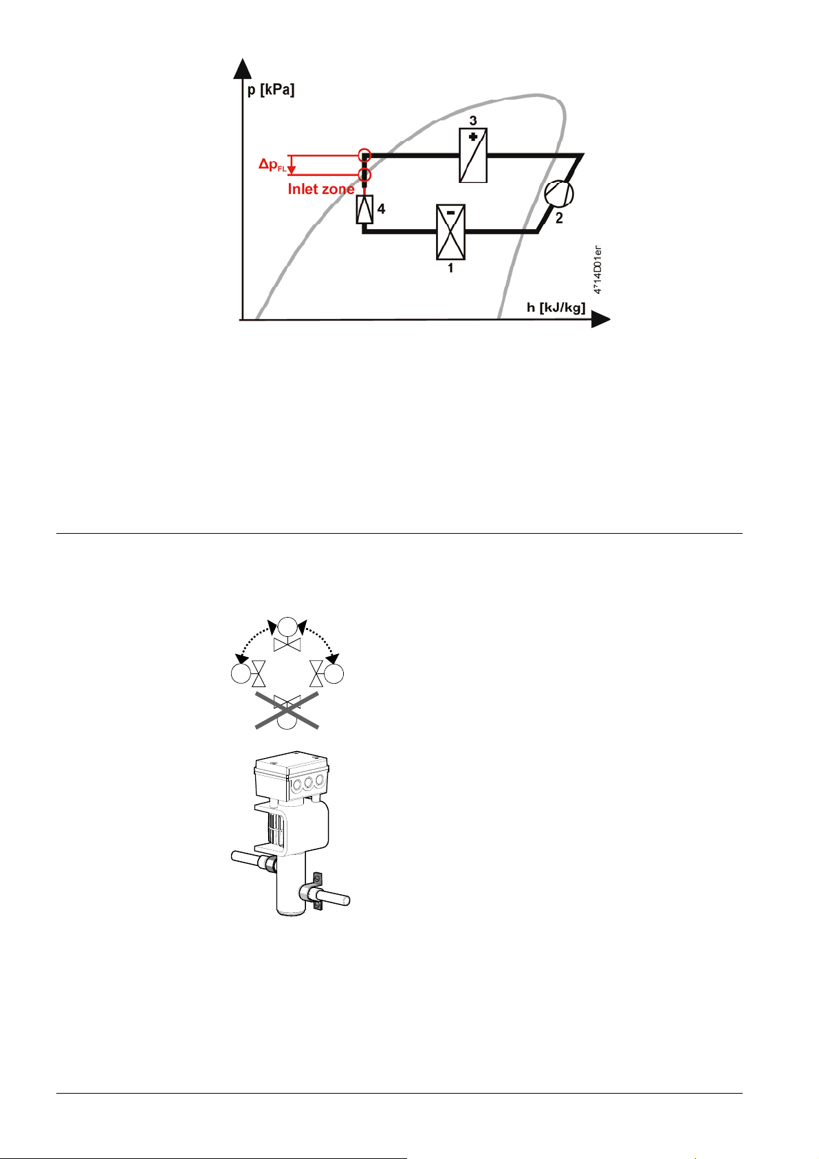
Engineering notes
1 = Evaporator
2 = Compressor
3 = Condenser
4 = Expansion valves
a) The differential pressure over reduction must be less than half the differential
pressure Δp
.
FL
b) The inlet path between diameter reduction and expansion valve inlet
Must straight for at least 600 mm
May not contain any valves
A filter / dryer must be mounted upstream of the expansion valve.
The valve is not explosion-proof.
It is not approved for use with ammonia (NH3, R717).
Mounting notes
The valve should be mounted and commissioned by qualified staff. The same applies
to the replacement electronics and the configuration of the controller (e.g. SAPHIR or
PolyCool).
• The refrigerant valves can be mounted in any orientation, but
90°
90°
upright mounting is preferable.
• Arrange the pipework in such a way that the valve is not
located at a low point in the plant where oil can collect.
• The pipes should be fitted in such a way that the alignment
does not distort the valve connections. Fix the valve body so
4716Z16
00441
that that it cannot vibrate. Vibration can lead to burst
connection pipes.
• Before soldering the pipes, ensure that the direction of flow
through the valve is correct.
• The pipes must be soldered with care. To avoid dirt and the
formation of scale (oxide), inert gas is recommended for
soldering.
• The flame should be large enough to ensure that the junction
heats up quickly and the valve does not get too hot.
• The flame should be directed away from the valve.
• During soldering, cool the valve with a wet cloth, for example,
to ensure that it does not become too hot.
• Port B must be sealed off when a 2-port valve (AB A) is
used.
• The valve body and the connected pipework should be
lagged.
• The actuator must not be lagged.
6/18
Siemens Modulating refrigerant valves with magnetic actuator, PS45 CE2N4714en
Building Technologies 30.05.2011
Page 7

The valve is supplied complete with mounting instructions 74 319 0232 0.
Maintenance
The refrigerant valve is maintenance-free.
Repair
The valve can not be repaired. It has to be replaced as a complete unit.
Disposal
Do not dispose of the actuator and its electrical and electronic components with
domestic waste.
The law may require special handling of certain components or it may make sense
from an ecological point of view.
Observe all applicable local laws.
Warranty
Observe all application-specific technical data.
If you ignore specified limits, Siemens Building Technologies / CPS Products will
nor assume any responsibility.
Technical data
Functional actuator data
Power supply Extra low-voltage only (SELV, PELV)
• AC 24 V
Operating voltage AC 24 V ± 20%
Frequency 45...65 Hz
Typical power consumption P
12 W
med
Standby < 1 W (valve closed)
Rated apparent power S
22 VA (for selecting the transformer)
NA
Required fuse 1.6...4 A (slow)
• DC 24 V
Operating voltage DC 20...30 V
Current draw 0.5 A / 2 A (max.)
Signal inputs Control signal Y DC 0/2...10 V or DC 0/4...20 mA
Impedance DC 0/2...10 V 100 kΩ / 5nF
Impedance DC 0 / 4...20 mA 240 Ω / 5nF
Forced control ZC
Input impedance 22 kΩ
Close valve (ZC connected to G0) < AC 1 V; < DC 0.8 V
Open valve (ZC connected to G) > AC 6 V; > DC 5 V
No function (ZC not wired) Positioning signal Y active
Signal outputs Position feedback signal U Voltage DC 0/2…10 V; load resistance ≥ 500 Ω
Current
Stroke detection
Nonlinearity
DC 0/4…20 mA; load resistance ≤ 500 Ω
Inductive
Accuracy ± 3 % full scale
Positioning time Positioning time < 1 s
Electrical connections Cable entry glands 3 x Ø 17 mm (for M16)
Min. wire cross-section 0.75 mm2
Max. cable length See «Connection type», page 5
Product data valve Permissible operating pressure max. 4.,5 MPa (45 bar) 1)
Max. differential pressure Δp
2.5 MPa (25 bar)
max
DN32: 200 kPa (2 bar)
Valve characteristic (stroke, kv) Linear (to VDI / VDE 2173)
Leakage rate (internally across seat) Max. 0.002% kvs or
Max. 1 Nl/h gas at Δp = 4 bar
Shut/off function, like solenoid normally closed
(NC) function
7/18
Siemens Modulating refrigerant valves with magnetic actuator, PS45 CE2N4714en
Building Technologies 30.05.2011
Page 8

External seal Hermetically sealed (fully welded,
no static or dynamic seals)
Permissible media Commonly used safety refrigerants (R22,
R134a, R404A, R407C, R410A, R507 etc.)
and R744 (CO
Not suitable for flammable refrigerants
);
2
2)
Medium temperature -40...120 °C; max. 140 °C for 10 min
Stroke resolution
ΔH
/
1 : 1000 (H = stroke)
H100
Hysteresis Typically 3 %
Mode of operation Modulating
Position when deenergized Control path A AB closed
Orientation Upright to horizontal
3)
Materials Valve body and parts Steel / CrNi steel
Seat / piston CrNi steel / brass
Sealing disk PTFE
Pipe connections Sleeves Internally soldered, CrNi steel
Dimensions and weight Dimensions See "Dimensions" page 11
Weight See "Dimensions" page 11
Standards CE conformity
To EMC requirements
Immunity EN 61000-6-2:[2005] Industrial
2004/108/EC
4)
Emission EN 61000-6-3:[2007] Residential
Electrical safety EN 60730-1
Protection class Class III as per EN 60730
Degree of pollution Degree 2 as per EN 60730
Housing protection
Upright to horizontal
Vibration
5)
EN 60068-2-6
IP65 as per EN 60529
3)
5 g acceleration, 10...150 Hz, 2.5 h
(5 g horizontal, max. 2 g upright)
Conformant to UL standards
CSA, Canada
C-tick
UL 873
C22.2 No. 24
N 474
Environmental compatibility ISO 14001 (environment)
ISO 9001 (quality)
SN 36350 (environmentally-compatible products)
RL 2002/95/EG (RoHS)
Permissible operating pressure PED 97/23/EC
Pressure accessories As per article 1, section 2.1.4
Fluid group 2 Without CE-marking as per article 3, section 3
(sound engineering practice)
1)
To EN 12284 tested with 1,43 x operating pressure at 65 bar
2)
For flammable refrigerants use ATEX certified refrigerant valves (CDV..MVL..)
3)
At 45 °C < T
shortening the service life of the valve electronics
4)
Transformer 160 VA (e.g. Siemens 4AM 3842-4TN00-0EA0)
5)
In case of strong vibrations, use high-flex stranded wires for safety reasons.
< 55 °C and 80 °C < T
amb
< 120 °C the valve must be installed on its side to avoid
med
General
environmental conditions
Operation
EN 60721-3-3
Transport
EN 60721-3-2
Storage
EN 60721-3-1
Climatic conditions Class 3K6 Class 2K3 Class 1K3
Temperature –25...55 °C –25...70 °C –5...45 °C
Humidity 10...100% r. h. < 95% r. h. 5...95% r. h.
8/18
Siemens Modulating refrigerant valves with magnetic actuator, PS45 CE2N4714en
Building Technologies 30.05.2011
Page 9

Connection terminals
Connection diagrams
Terminal assi
gnment
for controller with
4-wire connection
(to be preferred!)
Terminal assignment
for controller with
3-wire connection
Common transformer Separate transformer
Common transformer Separate transformer
Indication of valve position (only if required). DC 0...10 V → 0...100% volumetric flow V100
U
Twisted pairs. If the lines for AC 24 V power supply and the DC 0...10 V (DC 2...10 V,
DC 0... 20 mA, DC 4... 20 mA) positioning signal are routed separately, the AC 24 V line need
not be twisted.
Warning
DIL switch
Piping must be connected to potential earth!
Factory setting: Valve characteristics equal-percentage, positioning signal DC 0...10 V.
Details see "Configuration DIL switches", page 3.
Calibration
See "Calibration", page 4.
9/18
Siemens Modulating refrigerant valves with magnetic actuator, PS45 CE2N4714en
Building Technologies 30.05.2011
Page 10

Dimensions
Dimensions in mm
H4
D
H3
H1 H2
Type reference DN D L H1 H2 H3 H4 T M
[inch] [mm] [mm] [mm] [mm] [mm] [mm] [kg]
MVL661.15-0.4 15 5/8" 140 44 36 113 160 103 4.4
MVL661.15-1.0 15 5/8" 140 44 36 113 160 103 4.4
MVL661.20-2.5 20 7/8" 150 41 41 119 160 103 4.5
MVL661.25-6.3 25 1 1/8" 160 40 47 126 160 103 4.6
MVL661.32-12 32 1 3/8" 190 43 54 142 160 103 6.1
DN Nominal size
D Pipe connections [inch], internal dimension
T Depth
M Weight including packaging [kg]
Valve sizing with correction factor
The applications and tables on the following pages are designed for help with selecting
the valves. To select the correct valve, the following data is required:
• Application
− Expansion (starting on page 14)
− Hot-gas (starting on page 16)
− Suction throttle (starting on page 18)
• Refrigerant type
• Evaporating temperature t
• Condensing temperature t
• Refrigeration capacity Q
L
[°C]
0
[°C]
c
[kW]
0
To calculate the nominal capacity, use the following formula:
*
• k
[m³/h] = Q0 [kW] / K...*
vs
K... for expansion = KE
for hot-gas = KH
for suction throttle = KS
• The theoretical kv value for the nominal refrigeration capacity of the plant should not
be less than 50% of the kvs value of the selected valve.
10/18
Siemens Modulating refrigerant valves with magnetic actuator, PS45 CE2N4714en
Building Technologies 30.05.2011
Page 11

• For accurate valve sizing, we recommend the valve selection program "Refrigeration
VASP".
The application examples on the following pages deal with the principles only. They do
not include installation-specific details such as safety elements, refrigerant collectors,
etc.
Use of the MVL661..-.. as an expansion valve
Note
Capacity optimization
Application example
Note on interpolation
Observe engineering notes page 6
• Typical control range 20...100%.
• Increased capacity through better use of the evaporator
• The use of two or more compressors or compressor stages significantly increases
efficiency with low loads
• Especially suitable for fluctuating condensing and evaporating pressures
4
1
2
40153A
3
1 = MVL661..-..
2 = evaporator
3 = compressor
4 = condenser
Electronic superheat control is achieved by using additional control equipment
(e.g. PolyCool).
Refrigerant R407C; Q
The correct k
value for the MVL661..-.. valve needs to be determined.
vs
= 205 kW; to = –5 °C; tc = 35 °C
0
The important section of table KE for R407C (see page 12) is the area around the
working point. The correction factor KE relevant to the working point should be
determined by linear interpolation from the four guide values.
In practice, the KE, KH or KS value can be estimated because the theoretical k
ascertained will be rounded off by up to 30% to one of the ten available k
vs
-value
vs
-values,
allowing you to proceed directly at Step 4.
Step 1: For t
= 35, calculate the value for to = –10 between values 20 and 40 in the
c
table; result: 112
Step 2: For t
= 35, calculate the value for to = 0 between values 20 and 40 in the
c
table; result: 109
Step 3: For t
= –5, calculate the value for tc = 35 between correction factors 112
0
and 109; calculated in steps 1 and 2; result: 111
Step 4: Calculate the theoretical k
Step 5: Select the valve; the valve closest to the theoretical k
value; result: 1.85 m3/h
vs
value is the
vs
MVL661.20-2.5
Step 6: Check that the theoretical k
k
value
vs
value is not less than 50 % of the nominal
vs
11/18
Siemens Modulating refrigerant valves with magnetic actuator, PS45 CE2N4714en
Building Technologies 30.05.2011
Page 12

Capacity control
KE-R407C t0 = –10 °C t0 = 0 °C Interpolation at tc = 35 °C
tc = 20 °C 108 85 108 + [(113 – 108) x (35- 20) / (40 - 20)] 112
tc = 35 °C 112 109
tc = 40 °C 113 117 85 + [(117 - 85) x (35 - 20) / (40 - 20)] 109
Interpolation at t0 = -5 °C
112 +[(109 - 112) x (-5 - 0) / (-10 - 0)] 111
kv theoretical = 205 kW / 111 = 1.85 m3/h
Valve MVL661.20-2.5 is suitable, since: 1.85 m
3
/h / 2.5 m3/h x 100% = 74% (> 50%)
a) Refrigerant valve MVL661..-.. for capacity control of a dry expansion evaporator.
Suction pressure and temperature are monitored with a mechanical capacity
controller and reinjection valve.
• Typical control range 0...100%
• Energy-efficient operation with low loads
• Ideal control of temperature and dehumidification
40155A
MVL661
*
b) Refrigerant valve MVL661..-.. for capacity control of a chiller.
• Typical control range 10...100%
• Energy-efficient operation with low loads
• Allows wide adjustment of condensing and evaporating temperatures
• Ideal for use with plate heat exchangers
• Very high degree of frost protection
40156A
MVL661
Note
A larger valve may be required for low load operation than is needed for full load
conditions. To ensure that the selected valve will not be too small for low loads, sizing
should take account of both possibilities.
12/18
Siemens Modulating refrigerant valves with magnetic actuator, PS45 CE2N4714en
Building Technologies 30.05.2011
Page 13

Correction table KE
Expansion valve
R22 R134a
tc \ to -40 -30 -20 -10 0 10 tc \ to -40 -30 -20 -10 0 10
00 82 68 37 00 27
20 101 104 107 105 81 18 20 71 74 77 66 43
40 108 111 114 118 120 123 40 74 78 81 85 89 92
60 104 108 112 116 119 122 60 67 72 76 81 85 89
R744
tc \ to -40 -30 -20 -10 0 10
-20 226 149
00 262 264 241 166
20 245 247 247 246 213
R401A R402A
tc \ to -40 -30 -20 -10 0 10 tc \ to -40 -30 -20 -10 0 10
00 31 00 73 69 50
20 80 83 85 72 46 20 77 81 85 88 74 35
40 87 90 94 97 101 102 40 71 75 80 84 88 91
60 85 89 94 98 102 106 60 50 55 60 65 69 74
R404A R407A
tc \ to -40 -30 -20 -10 0 10 tc \ to -40 -30 -20 -10 0 10
00 69 63 44 00 79 67 40
20 70 74 78 81 68 30 20 91 95 98 102 82 30
40 61 65 70 74 78 81 40 89 94 98 102 106 110
60 36 41 46 51 55 59 60 72 77 82 87 92 96
R407B R407C
tc \ to -40 -30 -20 -10 0 10 tc \ to -40 -30 -20 -10 0 10
00 72 66 45 00 79 65 31
20 77 80 84 88 75 34 20 98 101 105 108 85 21
40 69 74 78 83 87 91 40 100 104 109 113 117 121
60 46 51 56 61 66 70 60 87 93 98 103 108 113
R410A R410B
tc \ to -40 -30 -20 -10 0 10 tc \ to -40 -30 -20 -10 0 10
00 116 117 91 12 00 112 112 87 11
20 125 130 133 137 120 69 20 122 126 129 132 115 66
40 119 124 129 133 137 140 40 119 124 128 131 134 137
60 90 96 101 106 110 114 60 98 103 108 112 115 118
R507
tc \ to -40 -30 -20 -10 0 10
00 72 66 47
20 78 81 83 86 71 33
40 74 78 81 84 87 90
60 53 57 61 64 68 71
• With superheat = 6 K With subcooling = 2 K Δp upstream of evaporator = 1.6 bar
• Δp condenser = 0.3 bar Δp evaporator = 0.3 bar
13/18
Siemens Modulating refrigerant valves with magnetic actuator, PS45 CE2N4714en
Building Technologies 30.05.2011
Page 14

Use of the MVL661..-.. as a hot-gas valve
The control valve throttles the capacity of a compressor stage. The hot gas passes
directly to the evaporator, thus permitting capacity control in the range from 100% down
to approximately 0%.
Indirect hot-gas
bypass application
Application example
With low loads, the evaporating and condensing pressures can fluctuate depending on
the type of pressure control. In such cases, evaporating pressure increases and
condensing pressure decreases. Due to the reduction in differential pressure across the
fully open valve, the volumetric flow rate will drop – the valve is undersized. This is why
the effective pressures must be taken into account when sizing the valve for low loads.
Refrigerant R507; 3 compressor stages; Q
Part load Q
0
KH-R507 t0 = 0 °C t0 = 10 °C Interpolation at tc = 23 °C
tc = 2 °C 14.4 9.0 14.4 + [(22.4 – 14.4) x (23 - 20) / (40 - 20)] 15.6
tc = 23 °C 15.6 11.0
tc = 40 °C 22.4 22.0 9.0 + [(22.0 – 9.0) x (23 - 20) / (40 - 20)] 11.0
Interpolation at t0 = 4 °C
15.6 + [(11.0 – 15.6) x (4 - 0) / (10 - 0)] 13.8
kvs theoretical = 28 kW / 13.8 = 2.03 m3/h
Valve MVL661.20-2.5 is suitable, since: 2.03 m
+
70179
Suitable for use in large refrigeration
MVL661
systems in air conditioning plant, to prevent
unacceptable temperature fluctuations
–
between the compressor stages.
= 75 kW; t0 = 4 °C; tc = 40 °C
0
per stage = 28 kW; t0= 4 °C; tc = 23 °C
3
/h / 2.5 m3/h x 100% = 81% (> 50%)
Direct hot-gas bypass
application
The control valve throttles the capacity of one compressor stage. The gas is fed to the
suction side of the compressor and then cooled using a reinjection valve. Capacity
control ranges from 100% down to approximately 10%.
+
MVL661
70180
Suitable for large refrigeration systems in air
conditioning applications with several
compressors or compressor stages, and
where the evaporator and compressor are
some distance apart (attention must be paid
–
to the oil return).
14/18
Siemens Modulating refrigerant valves with magnetic actuator, PS45 CE2N4714en
Building Technologies 30.05.2011
Page 15

Correction table KH
Hot-gas valve
R22 R134a
tc \ to -40 -30 -20 -10 0 10 tc \ to -40 -30 -20 -10 0 10
00 8.9 8.4 6.3 00 4.5
20 15.3 15.1 14.8 14.6 13.2 6.5 20 9.8 9.6 9.5 9.2 7.4
40 24.2 23.7 23.2 22.8 22.4 22.1 40 15.9 15.6 15.3 15.1 14.9 14.7
60 35.7 34.7 33.8 33.0 32.3 31.7 60 23.8 23.2 22.7 22.3 21.9 21.6
R744 R290
tc \ to -40 -30 -20 -10 0 10 tc \ to -40 -30 -20 -10 0 10
-20 38.1 30.5 00 10.9 10.0 6.5
00 60.9 59.8 58.1 47.1 20 18.0 17.7 17.4 17.1 15.0
20 87.3 84.9 82.5 80.2 76.1 40 27.3 26.7 26.2 25.8 25.4 25.1
60 38.2 37.2 36.4 35.7 35.1 34.5
R401A R402A
tc \ to -40 -30 -20 -10 0 10 tc \ to -40 -30 -20 -10 0 10
00 4.7 00 9.7 9.5 8.3
20 10.2 10.0 9.9 9.5 7.6 20 15.9 15.7 15.4 15.2 14.5 9.3
40 16.9 16.6 16.2 16.0 15.8 15.6 40 23.7 23.2 22.7 22.4 22.0 21.7
60 25.9 25.2 24.6 24.1 23.7 23.3 60 31.5 30.7 29.9 29.2 28.7 28.1
R404A R407A
tc \ to -40 -30 -20 -10 0 10 tc \ to -40 -30 -20 -10 0 10
00 9.4 9.2 7.8 00 8.9 8.6 6.7
20 15.2 15.0 14.8 14.6 13.9 8.6 20 15.7 15.4 15.2 15.0 14.1 8.0
40 22.3 21.8 21.5 21.1 20.9 20.6 40 24.9 24.4 23.9 23.5 23.1 22.8
60 28.8 28.0 27.4 26.8 26.4 25.9 60 35.9 34.9 34.0 33.2 32.6 32.0
R407B R407C
tc \ to -40 -30 -20 -10 0 10 tc \ to -40 -30 -20 -10 0 10
00 9.0 8.8 7.4 00 8.6 8.1 5.9
20 15.3 15.1 14.8 14.7 14.0 8.8 20 15.3 15.0 14.8 14.6 13.6 7.0
40 23.3 22.8 22.4 22.0 21.7 21.5 40 24.7 24.2 23.7 23.3 22.9 22.6
60 31.6 30.7 30.0 29.3 28.8 28.3 60 36.3 35.3 34.4 33.6 33.0 32.4
R410A R410B
tc \ to -40 -30 -20 -10 0 10 tc \ to -40 -30 -20 -10 0 10
00 14.5 14.3 13.2 6.2 00 14.3 14.1 12.9 6.1
20 24.2 23.7 23.3 23.0 22.1 15.9 20 23.8 23.3 22.9 22.5 21.6 15.5
40 36.8 35.9 35.1 34.4 33.7 33.1 40 36.5 35.6 34.7 33.9 33.2 32.5
60 50.0 48.5 47.2 46.0 44.9 43.8 60 50.7 49.1 47.7 46.4 45.2 44.0
R507 R1270
tc \ to -40 -30 -20 -10 0 10 tc \ to -40 -30 -20 -10 0 10
00 9.8 9.5 8.1 00 13.5 13.0 10.3
20 16.1 15.8 15.5 15.3 14.4 9.0 20 22.0 21.6 21.2 20.9 19.0 9.9
40 24.5 23.8 23.3 22.8 22.4 22.0 40 33.0 32.2 31.6 31.1 30.6 30.1
60 33.1 31.8 30.7 29.8 29.0 28.3 60 46.1 44.8 43.8 42.8 41.9 41.2
• With superheat = 6 K With subcooling = 2 K Δp upstream of evaporator = 1.6 bar
• Δp condenser = 0.3 bar Δp evaporator = 0.3 bar
15/18
Siemens Modulating refrigerant valves with magnetic actuator, PS45 CE2N4714en
Building Technologies 30.05.2011
Page 16

Use of the MVL661..-.. as a suction throttle valve
Application example
+
70177
Typical control range 50...100%.
Minimum stroke limit control:
MVL661
–
To ensure optimum cooling of the compressor,
either a capacity controller must be provided for
the compressor, or a minimum stroke must be set
via the valve electronics.
The minimum stroke can be limited to a maximum of 80%. At zero load, the minimum
stroke must be sufficient to ensure that the minimum gas velocity in the suction line is >
0.7 m/s and that the compressor is adequately cooled.
As the control valve closes, the evaporating temperature rises and the air cooling effect
decreases continuously. The electronic control system provides demand-based cooling
without unwanted dehumidification and costly retreatment of the air.
The pressure at the compressor inlet falls and the power consumption of the
compressor is reduced. The energy savings to be anticipated with low loads can be
determined from the compressor selection chart (power consumption at minimum
permissible suction pressure). Compressor energy savings of up to 40% can be
achieved.
The recommended differential pressure Δp
between 0.15 <
Δp
< 0.5 bar.
v100
across the fully open control valve is
v100
Refrigerant R134A; Q
Differential pressure across MVL661: Δp
= 9.5 kW; t0 = 4 °C; tc = 40 °C;
0
= 0.25 bar
v100
In this application example, t
, tc and Δp
0
are to be interpolated.
v100
KS-R134a t0 = 0 °C t0 = 10 °C Interpolation at t0 = 4 °C
0.15 / 20 2.2 2.7 2.2 + [(2.7 – 2.2) x (4 - 0) / (10 - 0)] 2.4
0.15 / 50 1.7 2.1 1.7 + [(2.1 – 1.7) x (4 - 0) / (10 - 0)] 1.9
0.45 / 20 3.6 4.5 3.6 + [(4.5 – 3.6) x (4 - 0) / (10 - 0)] 4.0
0.45 / 50 2.7 3.4 2.7 + [(3.4 – 2.7) x (4 - 0) / (10 - 0)] 3.0
t0 = 4 °C tc = 20 °C tc = 50 °C
Δp
0.15
v100
Δp
0.45
v100
tc = 40 °C
2.1 3.3
kvs theoretical = 9.5 kW / 2.5 = 3.8 m3/h
Valve MVL661.25-6.3 is suitable, since 3.8 m
It is recommended that the k
2.4 1.9 2.4 + [(1.9 – 2.4) x (40 - 20) / (50 - 20)] 2.1
4.0 3.0 4.0 + [(3.0 – 4.0) x (40 - 20) / (50 - 20)] 3.3
Δp
v100
+
0.15 Δp
0.45
v100
value be set to 63% = 4 m3/h
vs
50941A
Interpolation at tc = 40 °C
Interpolation at
2.1 + [(3.3 – 2.1) x (0.25 – 0.15) / (0.45 –
0.15)]
3
/h / 6.3 m3/h x 10 % = 60% (> 50%)
Δp
v100
2.5
0.25
Typical control range 10...100%.
The capacity controller ensures that the
compressor is adequately cooled, making it
–
MVL661
unnecessary to set a minimum stroke in the
refrigerant valve.
16/18
Siemens Modulating refrigerant valves with magnetic actuator, PS45 CE2N4714en
Building Technologies 30.05.2011
Page 17

Correction table KS
Suction throttle valve
tc R22 tc R134a
Δp
\ to -40 -30 -20 -10 0 10 Δp
v100
\ to-40 -30 -20 -10 0 10
v100
0.15 / 20 1.2 1.5 1.9 2.4 2.9 3.4 0.15 / 20 0.7 1.0 1.4 1.8 2.2 2.7
0.15 / 50 0.9 1.2 1.5 1.9 2.3 2.7 0.15 / 50 0.5 0.7 1.0 1.3 1.7 2.1
0.45 / 20 1.5 2.3 3.0 3.9 4.8 5.7 0.45 / 20 0.7 1.2 1.9 2.7 3.6 4.5
0.45 / 50 1.2 1.8 2.4 3.0 3.8 4.6 0.45 / 50 0.5 0.9 1.4 2.0 2.7 3.4
tc R152A tc R290
Δp
\ to -40 -30 -20 -10 0 10 Δp
v100
\ to-40 -30 -20 -10 0 10
v100
0.15 / 20 0.9 1.3 1.7 2.2 2.7 3.3 0.15 / 20 1.5 1.9 2.4 3.0 3.6 4.3
0.15 / 50 0.7 1.0 1.4 1.7 2.2 2.7 0.15 / 50 1.0 1.4 1.8 2.2 2.7 3.3
0.45 / 20 1.0 1.5 2.4 3.3 4.3 5.3 0.45 / 20 2.0 2.8 3.8 4.8 6.0 7.2
0.45 / 50 0.7 1.2 1.9 2.6 3.5 4.4 0.45 / 50 1.4 2.1 2.8 3.6 4.5 5.5
tc R401A tc R402A
Δp
\ to -40 -30 -20 -10 0 10 Δp
v100
\ to-40 -30 -20 -10 0 10
v100
0.15 / 20 0.8 1.1 1.5 1.9 2.3 2.9 0.15 / 20 1.1 1.4 1.8 2.2 2.7 3.3
0.15 / 50 0.6 0.8 1.1 1.5 1.8 2.3 0.15 / 50 0.7 0.9 1.2 1.5 1.8 2.3
0.45 / 20 0.8 1.3 2.1 2.9 3.7 4.7 0.45 / 20 1.5 2.2 2.9 3.7 4.6 5.6
0.45 / 50 0.6 1.0 1.6 2.3 3.0 3.7 0.45 / 50 0.9 1.4 1.9 2.4 3.1 3.8
tc R404A tc R407A
Δp
\ to -40 -30 -20 -10 0 10 Δp
v100
\ to-40 -30 -20 -10 0 10
v100
0.15 / 20 1.0 1.3 1.7 2.2 2.7 3.3 0.15 / 20 1.0 1.4 1.8 2.3 2.9 3.5
0.15 / 50 0.6 0.8 1.1 1.4 1.7 2.1 0.15 / 50 0.7 1.0 1.3 1.6 2.1 2.6
0.45 / 20 1.4 2.1 2.8 3.6 4.5 5.5 0.45 / 20 1.3 2.0 2.9 3.8 4.7 5.9
0.45 / 50 0.8 1.2 1.7 2.3 2.9 3.6 0.45 / 50 0.9 1.4 2.0 2.7 3.4 4.3
tc R407B tc R407C
Δp
\ to -40 -30 -20 -10 0 10 Δp
v100
\ to-40 -30 -20 -10 0 10
v100
0.15 / 20 1.0 1.3 1.7 2.2 2.7 3.3 0.15 / 20 1.0 1.4 1.8 2.3 2.9 3.5
0.15 / 50 0.6 0.8 1.1 1.4 1.8 2.2 0.15 / 50 0.7 1.0 1.3 1.7 2.1 2.6
0.45 / 20 1.3 2.0 2.7 3.5 4.5 5.5 0.45 / 20 1.3 2.0 2.8 3.8 4.8 5.9
0.45 / 50 0.8 1.2 1.7 2.3 3.0 3.8 0.45 / 50 0.9 1.4 2.1 2.8 3.5 4.4
tc R410A tc R410B
Δp
\ to -40 -30 -20 -10 0 10 Δp
v100
\ to-40 -30 -20 -10 0 10
v100
0.15 / 20 1.5 2.0 2.5 3.0 3.6 4.4 0.15 / 20 1.5 1.9 2.4 2.9 3.6 4.2
0.15 / 50 1.0 1.3 1.7 2.1 2.6 3.1 0.15 / 50 1.0 1.3 1.7 2.1 2.6 3.1
0.45 / 20 2.3 3.1 4.0 5.0 6.1 7.4 0.45 / 20 2.3 3.1 3.9 4.9 6.0 7.2
0.45 / 50 1.6 2.1 2.8 3.5 4.4 5.3 0.45 / 50 1.6 2.1 2.8 3.5 4.3 5.2
• With superheat = 6 K With subcooling = 2 K Δp upstream of evaporator = 1.6 bar
• Δp condenser = 0.3 bar Δp evaporator = 0.3 bar
Revision numbers
Product number Valid from rev. no.
MVL661.15-0.4
MVL661.15-1.0
MVL661.20-2.5
MVL661.25-6.3
MVL661.32-12
Siemens Modulating refrigerant valves with magnetic actuator, PS45 CE2N4714en
Building Technologies 30.05.2011
C
C
D
C
C
17/18
Page 18

s
18/18
Siemens Modulating refrigerant valves with magnetic actuator, PS45 CE2N4714en
Building Technologies 30.05.2011
2011 Siemens Switzerland Ltd Subject to change
 Loading...