

Page 1
722
4
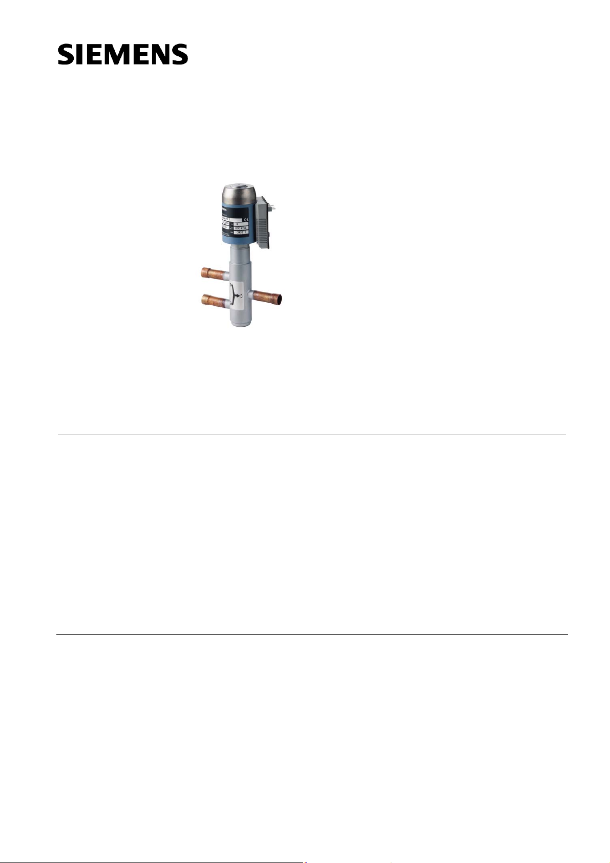
Modulating refrigerant
M3FK..LX..
valves with magnetic
actuator, PN 32
hermetically sealed, for condenser control
• Mixing or straight-through valves with magnetic actuator for modulating
capacity control of condensers.
• Short positioning time (approx. 1 s)
• High resolution
• High rangeability
• Hermetically sealed
• Versatile electrical interface
• Friction-free
• Port 1 -> 3 closed when de-energized
• Robust and maintenance-free
Use
CE2N4722en
08.06.2010
The M3FK..LX.. mixing or straight-through valves with magnetic actuator can be used
for modulating capacity control of condensers. They may be used for liquid or gas
control.
Suitable for safety refrigerants such as R22, R134a, R404A, R407C, R507, etc.
Building Technologies
Page 2
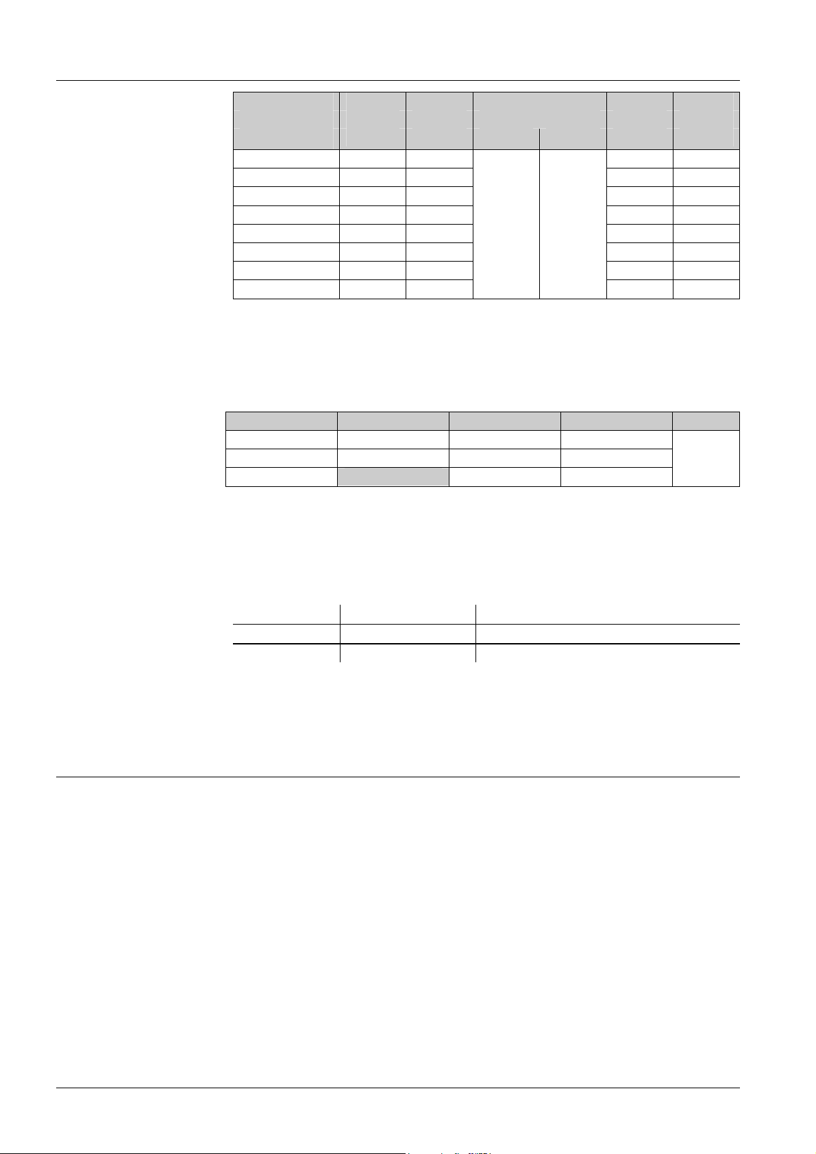
Type summary
Accessories /
ZM.. terminal housing
Order
Type reference DN kvs Δp
Liquid Gas
[m3/h] [MPa] [bar] [VA] [W]
M3FK15LX06
M3FK15LX15
M3FK15LX
M3FK20LX
M3FK25LX
M3FK32LX
M3FK40LX
M3FK50LX
= Maximum permissible differential pressure across the valve’s control path 1 → 3 valid for the
Δp
max
entire actuating range
= Rated apparent power for transformer selection
S
NA
P
= Typical power consumption
med
k
= Nominal flow rate of cold water through the fully open valve (H
vs
100 kPa (1 bar), to VDI 2173
15 0.6 13 3
15 1.5 13 3
15 3.0 13 3
20 5.0 16 4
25 8.0 16 4
0.2 0.8
32 12.0 20 5
40 20.0 40 10
50 30.0
SNA P
max
40 10
) by a differential pressure of
100
med
Type reference Operating voltage Positioning signal Working range Data sheet
ZM101/A AC 24 V DC 0…10 V DC 4…8 V
ZM121/A AC 24 V DC 4…20 mA DC 8…16 mA
ZM111 DC 0…20 V Phs DC 10…15 V Phs
For the ZM101/A and ZM121/A types also the DC 0…20 V Phs positioning signal is possible without
operating voltage.
N4591
The M3FK..LX.. valve and the ZM.. or ZM../A terminal housing must be ordered
separately.
When placing an order, please specify the quantity, product description and type code.
Type reference Stock number Description
M3FK15LX M3FK15LX Refrigerant valve
ZM101/A ZM101/A Terminal housing
Delivery
Rev. no.
Valves and terminal housings are packed separately.
Overview table, see page 9.
Technical and mechanical design
The armature or magnetic core is designed as a floating component within the pressure
system, so that no external shaft gland is required. The leakage losses common with
moving parts are thus avoided. The valve cross-section allows for easy flow whether
the valve is fully or only partially open. This reduces pressure losses and ensures quiet
operation.
The valves are fitted with extended female solder unions, making pipe connection easy.
The control signal is converted in the ZM../A terminal housing into a phase cut signal,
which generates a magnetic field in the coil. This causes the only moving part, the
armature, to change its position in accordance with the interacting forces (magnetic
field, counter-spring, hydraulics etc.). The armature responds rapidly to any change in
signal, transferring the corresponding movement directly to the control disc, enabling
fast changes in load to be corrected quickly and accurately.
The force of the counter-spring closes the valve automatically (control path ports 1 -> 3)
if the power is switched off or fails.
2/10
Siemens Modulating refrigerant valves with magnetic actuator, PN 32 CE2N4722en
Building Technologies 08.06.2010
Page 3
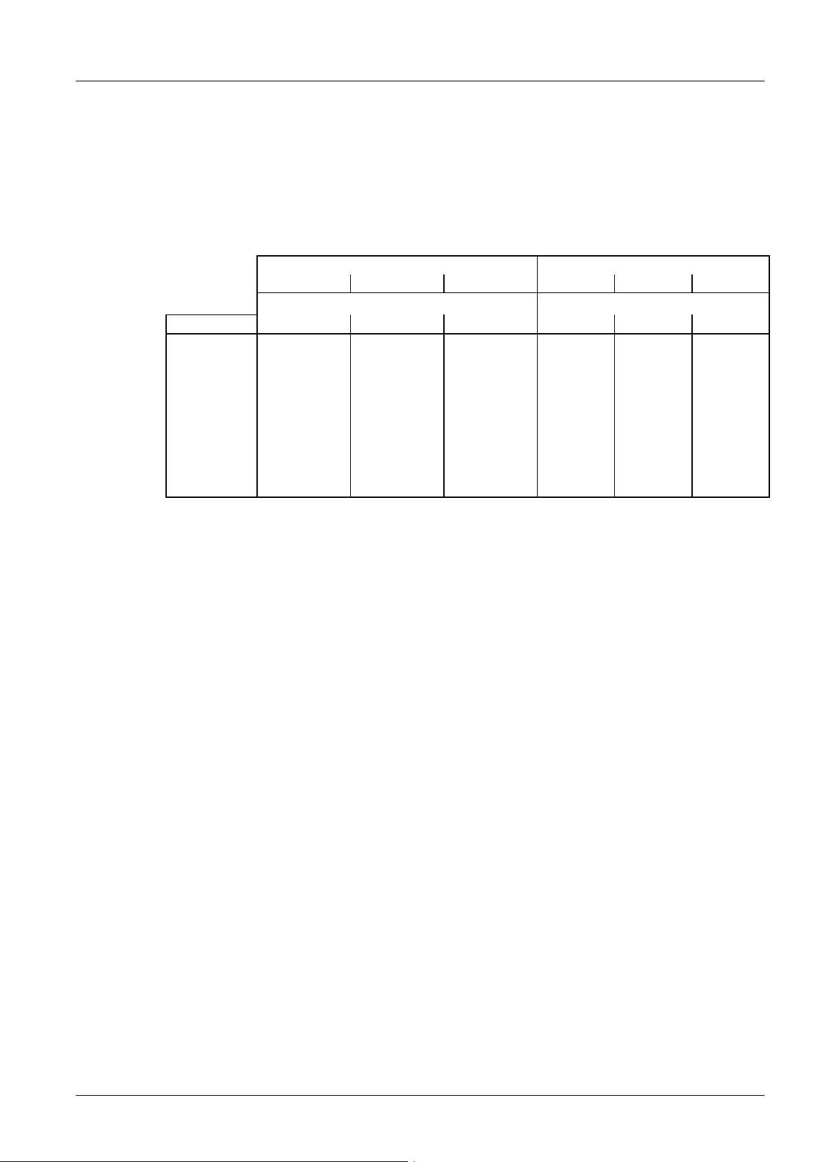
Sizing
Refrigeration capacity
Q
0
Selection table for
approximate guide to
valve size
Hot gas Liquid
R407C (R22) R134a (R12) R404A / R507 R407C (R22) R134a (R12) R404A R507
Condensation temperature tc [°C] Liquid temperature tfl [°C]
Valve type 30 40 50 30 40 50 30 40 50 30 40 30 40 30 40
M3FK15LX06 4.5 4.0 3.6 3.7 3.3 2.9 3.6 3.2 2.9 21 19 20 18 15 12
M3FK15LX15 11 10 8.9 9.2 8.2 7.2 8.9 8.0 7.2 54 49 51 45 37 31
M3FK15LX 22 20 18 18 16 14 18 16 14 107 97 102 91 74 62
M3FK20LX 37 33 30 31 27 24 30 27 24 179 162 170 151 124 103
M3FK25LX 59 53 48 49 44 38 47 43 38 286 259 272 242 199 165
M3FK32LX 89 80 72 74 66 57 71 64 58 429 389 408 364 298 248
M3FK40LX 149 134 119 123 109 96 119 107 96 715 648 681 606 497 413
M3FK50LX 223 201 179 184 164 143 178 160 144 1073 971 1021 909 745 619
Correct valve sizing (to ensure a sufficiently large pressure drop Δp
100 across the fully
v
open valve) is the key to the correct operation of a refrigeration unit. All the components
must be coordinated, and this can be ensured only by the refrigeration specialist.
The application examples on pages 5 and show the recommended pressure drop in
each case.
Pressure differential ∆p
in kW at an evaporation temperature t
= 0.5 bar across the fully-open valve. Nominal capacity Q0
V100
of 5 °C and a liquid temperature tfl of 30 °C.
o
Δp
= Differential pressure across the fully open valve (control path 1 → 3) by a volume flow
v100
V
100
3/10
Siemens Modulating refrigerant valves with magnetic actuator, PN 32 CE2N4722en
Building Technologies 08.06.2010
Page 4

Selection chart
+10
+5
0
-5
-10
-15
-20
]
-25
C
°
[
-30
0
t
-35
-40
5
2
+
+10
+5
-10
-15
-20
-25
-30
-35
-40
+10
-10
-15
-20
-25
-30
-35
-40
]
0
C
°
[
l
f
-5
t
+5
0
-5
+5°C
]
C
°
[
0
t
]
C
°
[
0
t
50320A
0
6
0
7
5
4
3
p
[bar]
Δ
0
0
5
5
4
3
3
2
+
+
+
]
C
°
[
l
f
t
5
0
5
0
4
4
3
3
+
+
+
+
0
0
5
5
5
6
5
6
+
+
+
+
5
0
5
0
5
6
6
5
5
4
+
+
+
+
+
+
R134a
(R12)
V
p
Δ
V
[bar]
,
,
,
1
0
,
1
,
0
0
0
7
5
,
,
,
0
0
0
2
,
,
0
0
t
4
3
2
,
,
0
0
R407C
(R22)
2
3
4
5
7
0
[bar]
p
Δ
V
5
2
+
4
4
3
3
+
+
+
+
]
C
°
[
l
f
t
6
6
5
5
+
+
+
+
R404A
R507
5
0
5
0
5
0
5
0
1
,
,
,
0
0
0
,
,
,
0
0
+
0
4
+
0
2
+
]
C
°
[
l
f
V
p
Δ
0
6
+
0
4
+
0
2
+
]
C
°
[
l
t
f
0
6
+
0
4
+
0
2
+
]
C
°
[
l
t
f
(R502)
1500
1000
800
600
500
400
300
200
150
100
80
60
50
40
30
20
15
10
8
6
5
]
W
k
[
0
.
Q
t0 = Evaporation temperature [°C]
= Condensation temperature [°C]
t
c
= tc - degree of sub-cooling [°C]
t
fl
Q
= Refrigeration capacity [kW]
0
m = Mass flow of refrigerant [kg/h]
= Admissible differential pressure
Δp
v100
[bar], installation-specific
0
0
0
0
5
M
3
F
K
5
0
L
0
0
0
0
2
0
0
0
0
1
0
0
0
5
0
0
0
3
0
0
0
2
0
0
0
1
0
0
6
0
0
4
0
0
3
0
0
2
0
0
1
]
h
/
g
k
[
.
m
X
M
3
F
K
4
0
L
X
M
3
F
K
3
2
L
X
M
3
F
K
2
5
L
X
M
3
F
K
2
0
L
X
M
3
F
K
1
5
L
X
M
3
F
K
1
5
L
X
1
5
M
3
F
K
1
5
L
X
0
6
= Nominal flow rate [m3/h] of cold water through
k
vs
the fully open valve (H
) by a differential
100
k
v
s
3
0
k
v
s
2
0
k
v
s
1
2
k
v
s
8
k
v
s
5
k
v
s
3
k
v
s
1
,
5
k
v
s
0
,
6
pressure of 100 kPa (1 bar)
4/10
Siemens Modulating refrigerant valves with magnetic actuator, PN 32 CE2N4722en
Building Technologies 08.06.2010
Page 5
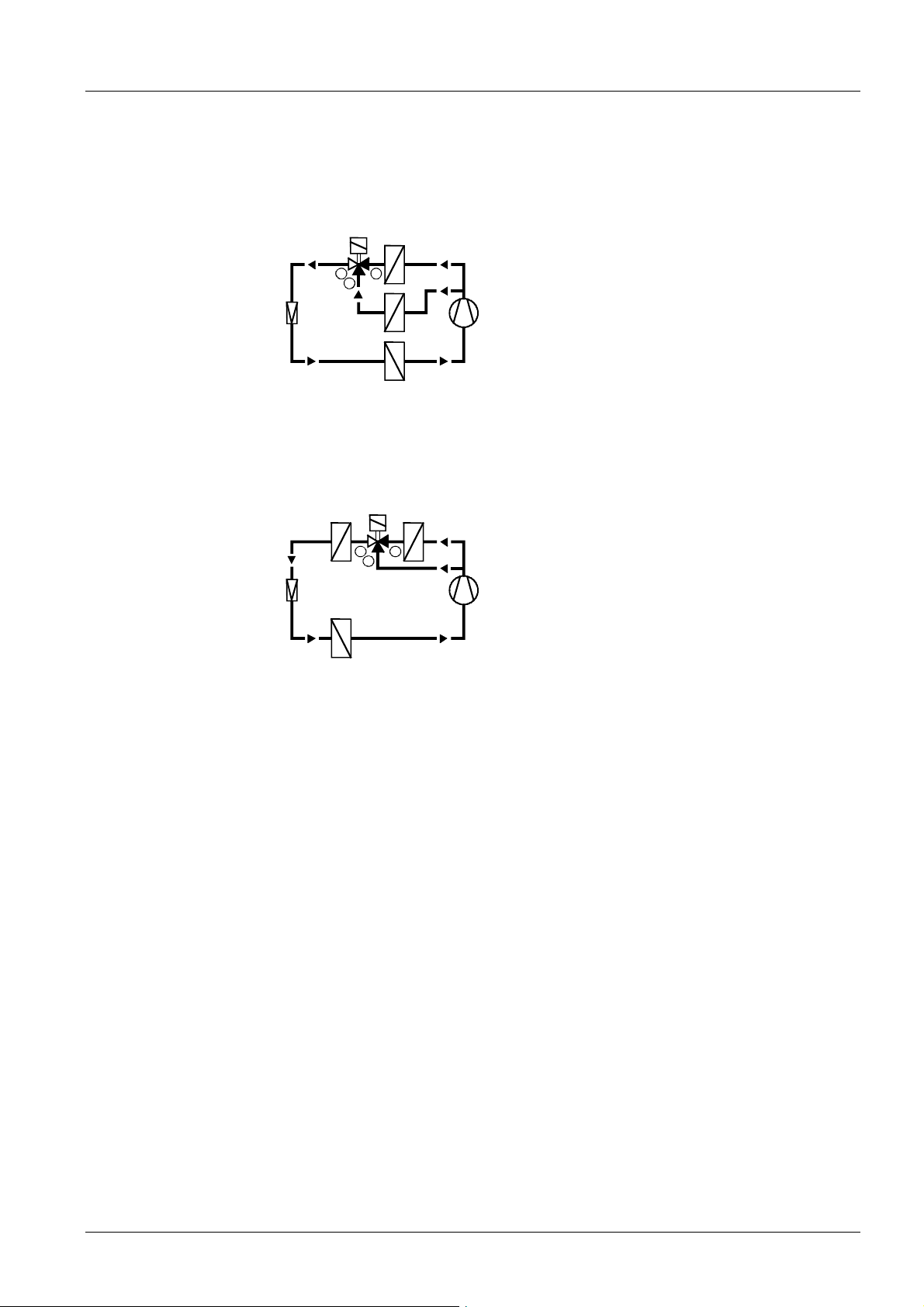
Application examples
3-way hot-gas bypass
control
Hot-gas control
The diagrams shown here are principles only, without installation-specific details.
The heat recovery condenser is connected in parallel with the main condenser and is
controlled on the liquid side by a mixing valve.
Recommended pressure drop Δp
(control path 1 → 3) 0.5 < Δp
+
321
+
940239
–
V100
across the fully-open valve
V100
< 1 bar (see selection chart)
Example:
Refrigeration capacity Q
Refrigerant
Condensation temperature t
Evaporation temperature t
Liquid temperature t
Selected valve
Actual differential pressure Δp
0
c
0
fl
across valve
v100
73 kW
50 °C
+ 5 °C
45 °C
M3FK15LX
0,32 bar
The heat-recovery condenser is connected in series upstream of the main condenser
(the most common application). The selected control valve is sized for hot gas (see
data sheet 4721).
Recommended pressure drop Δp
(control path 1 → 3) 0.5 < Δp
+
321
–
+
V100
940240
across the fully-open valve
V100
< 1 bar (see selection chart)
Example:
Refrigeration capacity Q
Refrigerant
Condensation temperature t
Evaporation temperature
Liquid temperature t
Selected valve
Actual differential pressure Δp
0
0
fl
c
across valve
v100
M3FK32LX
0,45 bar
R22
73 kW
R22
50 °C
5 °C
45 °C
5/10
Siemens Modulating refrigerant valves with magnetic actuator, PN 32 CE2N4722en
Building Technologies 08.06.2010
Page 6

Mounting notes
Caution
Mounting instructions are enclosed with the valve:
• Nr. 35551 (valve)
• Nr. 35541 (ZM.. terminal housing)
90°
90°
• The refrigerant valves can be mounted in any
orientation, but upright mounting is preferable.
• The pipes should be fitted such that the alignment does
not distort the valve connections. The valve body
should be fixed such that it cannot vibrate. Vibration can
lead to burst connection pipes.
• Before soldering the pipes, ensure that the direction of
4722Z01
flow through the valve is correct.
• The pipes must be soldered with care. To avoid dirt and
the formation of scale (oxide), inert gas is
recommended for soldering.
• The flame should be large enough to ensure that the
junction heats up quickly and the valve does not get too
hot.
4721Z02
• The flame should be directed away from the valve.
• During soldering, cool the valve with a wet cloth, for
example, to ensure that it does not become too hot
• Port 2 must be sealed off when the valve is used in a
straight-through application (1 → 3).
• The valve body and the connected pipework should be
lagged.
• The actuator must not be lagged.
Always switch off the power supply before connecting or disconnecting the ZM..
terminal housing.
Maintenance
Repair
Disposal
Warranty
The M3FK..LX.. modulating control valves are maintenance-free.
The valve cannot be repaired. It has to be replaced as a complete unit.
The device must not be disposed of together with domestic waste. This applies in
particular to the PCB.
Legislation may demand special handling of certain components, or it may be sensible
from an ecological point of view
Current local legislation must be observed
.
Application-specific technical data must be observed.
If specified limits are not observed, Siemens Switzerland Ltd / HVAC Products
will nor assume any responsibility.
6/10
Siemens Modulating refrigerant valves with magnetic actuator, PN 32 CE2N4722en
Building Technologies 08.06.2010
Page 7

Technical data
Functional actuator data
Power supply
Extra low-voltage only (SELV, PELV)
Operating voltage
1)
AC 24 V + 15 % / -10 %
Frequency 50…60 Hz
Typical power consumption P
refer to «Type summary» table
med
Rated apparent power SNA refer to «Type summary» table
Required fuse IF 1.6…4 A, slow
Input
Positioning signal ZM101/A DC 0…10 V or DC 0…20 V Phs (phase cut)
ZM121/A DC 4…20 mA or DC 0…20 V Phs
ZM111 DC 0…20 V Phs
Input resistance DC 0…10 V > 100 kΩ
Input resistance DC 4…20 mA < 150 Ω
Positioning time Positioning time < 1 s
Electrical connections Cable entry 2 x Pg11 (ZM101/A, ZM121/A)
Connection terminals max. 1 x 4 mm2 wire cross-section
Min. wire cross-section 0.75 mm2
Functional valve data PN class PN 32 to EN 1333
Permissible operating pressure 3.2 MPa (40 bar)
Max. differential pressure Δp
2 → 3
Leakage at ∆p = 100 kPa (1 bar) 1 → 3
2 → 3
1 → 3
max
refer to «Type summary» table
0.8 MPa (8 bar)
max. 0.05 % kvs
max. 0.5 % k
vs
Valve characteristic (stroke, kv) linear (to VDI / VDE 2173), optimized in low
opening range
Permissible media for safety refrigerants (R22, R134a, R404A,
R407C, R507 etc.).
Not suited for ammonia (R717)
Medium temperature -40...120 °C
Position when de-energized 1 → 3 closed
Orientation upright to horizontal
Type of operation modulating
Materials Valve body steel
Pipe connections CU-pipe
Seat / inner valve brass / CrNi steel
Dimensions and weight Dimensions refer to «Dimensions»
Weight refer to table in «Dimensions»
Pipe connections Sleeves Extended female solder unions
Norms and Standards CE conformity
to EMV-requirements
Immunity EN 61000-6-2:[2005] Industrial
2004/108/EC
2)
Emission EN 61000-6-3:[2007] Residential
Electrical safety EN 60730-1
Housing protection
Upright to horizontal IP54 to EN 60529
Environmental compatibility ISO 14001 (Environment)
ISO 9001 (Quality)
SN 36350 (Environmentally compatible
products)
RL 2002/95/EC (RoHS)
7/10
Siemens Modulating refrigerant valves with magnetic actuator, PN 32 CE2N4722en
Building Technologies 08.06.2010
Page 8

Pressure Equipment directive PED 97/23/EC
Pressure accessories as per article 1, section 2.1.4
Fluid group 2 DN15…DN32
Fluid group 1 DN15…DN25
• without CE-marking as per article 3,
section 3 (sound engineering practice)
Fluid group 2 DN40…DN50 • category I, module A, with CE-marking
1)
No operating voltage is required for the DC 0…20 V Phs power positioning signal.
2)
Transformer 160 VA (e.g. Siemens 4AM 3842-4TN00-0EA0)
General
environmental conditions
Climatic conditions
Temperature
Humidity
Operation
EN 60721-3-3
Transport
EN 60721-3-2
Storage
EN 60721-3-1
Class 3K6 Class 2K3 Class 1K3
-25...55 °C -25...70 °C -5...45 °C
10...100 % r.h. < 95 % r.h. 5...95 % r.h.
Connection terminals
Warning
Connection diagrams
If a ZM../A terminal housing is used with DC 0...20 V Phs (phase cut), AC 24 V must
not be connected!
Always switch off the power supply before connecting or disconnecting the ZM..
terminal housing.
ZM101/A
1
2
3
4
5
6
ZM121/A
1
2
3
4
5
6
(DC 0...10 V or DC 0...20 V Phs)
~
Supply
~
AC 24 V
–
Positioning signal
+
DC 0...10 V
1
2
3
4
–
5
+
6
DC 0...20 V Phs (phase cut)
(DC 4...20 mA oder DC 0...20 V Phs)
~
Supply
~
AC 24 V
–
Positioning signal
+
DC 4...20 mA
1
2
3
4
–
5
+
6
DC 0...20 V Phs (phase cut)
(DC 0...20 V Phs)
ZM111
1
2
3
4
5
6
DC 0...20 V Phs
twisted
pairs
Refer to data sheet N4591 for the ZM.. terminal housings
4721Z03en
8/10
Siemens Modulating refrigerant valves with magnetic actuator, PN 32 CE2N4722en
Building Technologies 08.06.2010
Page 9

Dimensions
Dimensions in mm
D
A
B
1
3
2
L
9H702
3
H
C
2
H
2
H
1
H
DN ø D L H1 H2 H3 A B C W
Valve type [mm] [inches] [kg]
M3FK15LX06 15 5/8 150 57 25 164 60 73 67 2.6
M3FK15LX15 15 5/8 150 57 25 164 60 73 67 2.6
M3FK15LX 15 5/8 150 57 25 164 60 73 67 2.6
Revision numbers
M3FK20LX 20 7/8 170 62 30 173 70 78 67 3.5
M3FK25LX 25 1 1/8 200 66 36 177 70 78 71 4.2
M3FK32LX 32 1 3/8 250 91 43 197 80 84 80 6.0
M3FK40LX 40 1 5/8 300 92 50 202 100 94 98 10.7
M3FK50LX 50 2 1/8 350 102 60 202 100 94 85 12.0
D : Pipe connections
W : Weight (incl. packaging)
Type reference Valid up to rev. No.
M3FK15LX06
M3FK15LX15
M3FK15LX
M3FK20LX
M3FK25LX
M3FK32LX
M3FK40LX
M3FK50LX
..F
..F
..F
..F
..F
..G
..H
..H
9/10
Siemens Modulating refrigerant valves with magnetic actuator, PN 32 CE2N4722en
Building Technologies 08.06.2010
Page 10

ge
10/10
Siemens Modulating refrigerant valves with magnetic actuator, PN 32 CE2N4722en
Building Technologies 08.06.2010
2010 Siemens Switzerland Ltd Subject to chan
 Loading...