

Page 1
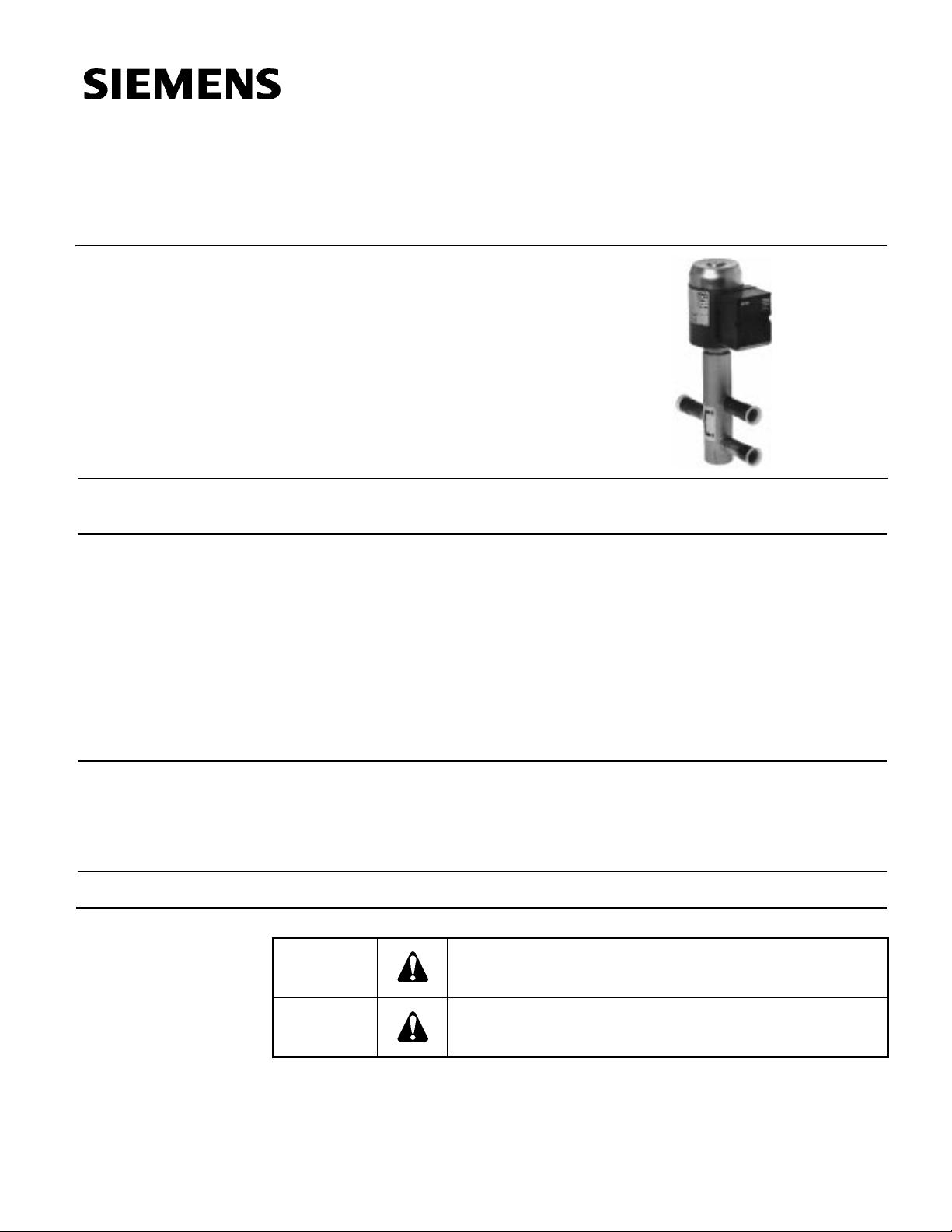
M3FB…LX… Series
Modulating Control Valve
for Hot Gas Control
Technical Instructions
Document No. CA2N4721E-P25
Rev. 1, February, 2000
Description
Features
Application
Product Numbers
Valves with magnetic actuator for modulating capacity control of refrigeration units and
for heat recovery.
•
Quick positioning time (approx. 1 second)
•
High resolution (> 1 : 200)
•
High rangeability
•
Hermetically sealed
•
Versatile electrical inter f ac e
•
Low friction
•
Port 1 → 3 closed when de-energized
•
Heavy-duty and maintenance-free
The M3FB...LX... three-way or straight-through valves with magnetic actuator are used
for modulating capacity control of refrigeration units and for heat recovery. They may be
used as hot gas diverting or straight-through valves.
Suitable for safety refrigerants suc h as R22, R13 4a, R40 4A, R40 7C and R507 .
See
Warning/Caution Notations
Table 1.
WARNING:
CAUTION:
Personal injury/loss of life may occur if a procedure is not
performed as specified.
Equipment damage may occur if the user does not follow a
procedure as specified.
Siemens Building Technologies, Inc.
Page 2
Technical Instructions M3FB…LX… Series Modulating Control Valve
Document Number CA2N4721E-P25 for Hot Gas Control
Rev. 1, February, 2000
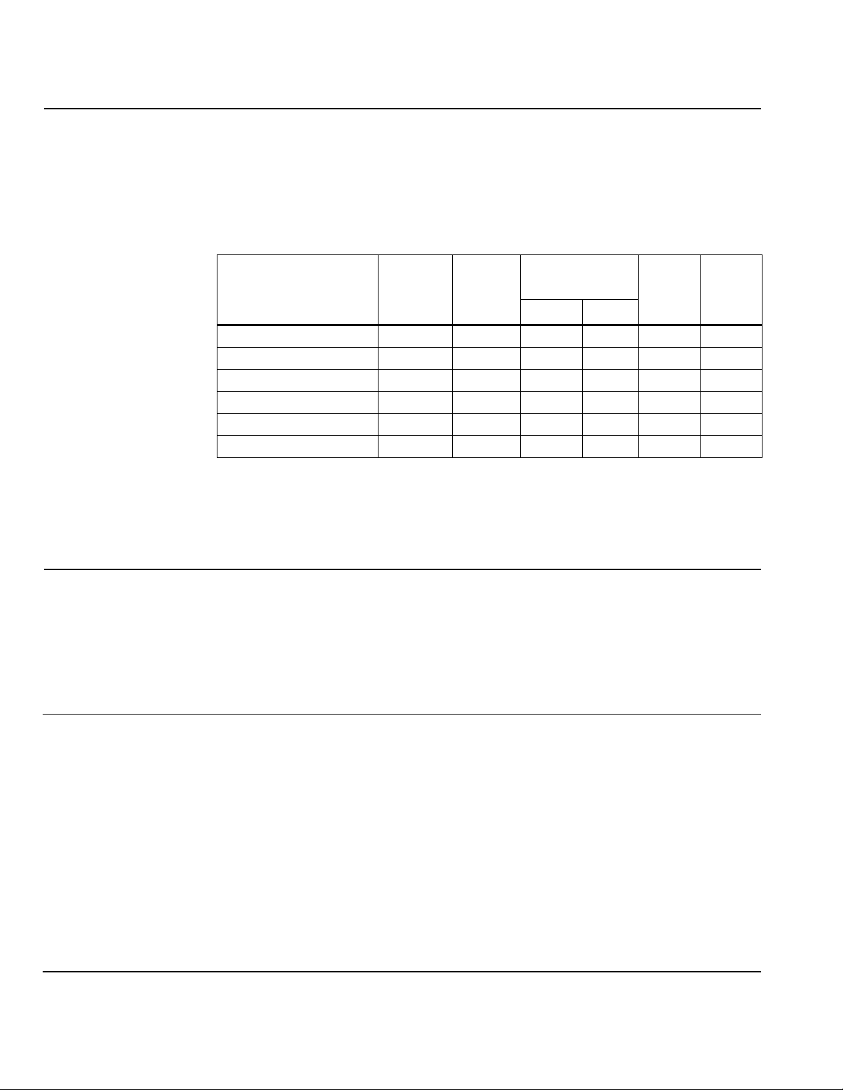
Ordering
The M3FB...LX... valve and the ZM... or ZM.../A module must be ordered separately.
When placing an order, specify the quantity, product number and product description.
Example :
1 M3FB15LX/A control valve and 1 ZM101/A module.
Table 1. Product Numbers.
N
Valve Product Number
(Without ZM...)
Line Size
[in]
1
Cv
→→→→
3
∆∆∆∆
1
max
p
v
3
→→→→
P
[VA]
P
[VA]
[gpm]
[psi] [bar]
M3FB15LX06/A
M3FB15LX15/A
M3FB15LX/A
M3FB20LX/A
M3FB25LX/A
M3FB32LX
1/2 0.7 319 22 26 6
1/2 1.8 319 22 26 6
1/2 3.5 319 22 26 6
3/4 5.9 261 18 26 6
1 9.4 174 12 40 10
1-1/4 14.0 116 8 40 10
Key :
max
∆
p
= Max. admissible pressure differential
v
N
P
P
= Nominal power
med
= Mean operating power
Cv = Flow rate tolerance ±10 %
med
Technical Design
Mechanical Design
The armature or magnetic core is designed as a floating component within the pressure
system, so that no external shaft gland is required. Therefore, leakage losses common
with moving parts are avoided. The valve cross-section allows for easy flow whether
the valve is fully or only partially open. This reduces pressure losses and ensures quiet
operation.
The valves are fitted with extended female solder unions, making pipe connections
easy.
The control signal is converted in the ZM.../A module into a phase cut signal, which
generates a magnetic field in the coil. This causes the only moving part, the armature,
to change its position in accordance with the interacting forces (magnetic field, counterspring, hydraulics etc.). The armature responds rapidly to any change in signal,
transferring the corresponding movement directly to the control disc, enabling fast
changes in load to be corrected quickly and accurately.
The valve is normally closed. A spring closes the valve automatically if the power is
switched off or fails.
Page 2
Siemens Building Technologies, Inc.
Page 3
M3FB…LX… Series Modulating Control Valve Technical Instructions
for Hot Gas Control Document Number CA2N4721E-P25
Rev. 1, February, 2000
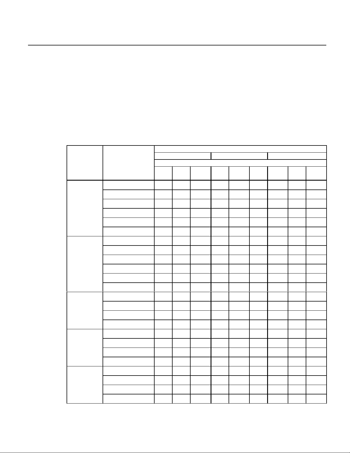
Sizing
Table 2
See
NOTE:
.
Correct valve sizing (to ensure a sufficiently large pressure drop ∆p
100
v
across
the fully open valve) is the key to the correct operation of a refrigeration unit.
All the components must be coordinated, and this can be ensured only by the
refrigeration specialist.
The application examples that follow show the recommended pressure drop
in each case.
Refrigeration capacity in tons
Nominal capacity in tons at evaporation temperature t
c
= 41°F (5 °C)
Table 2. Selection Table for Hot-Gas Applications.
(Approximate Guide to Valve Size)
Refrigerant
R407C (R22) R134a (R12) R404A / R507
Condensation temperature tc [°F]
v100
p
∆∆∆∆
Valve Product
122 104 86 122 104 86 122 104 86
Number
0.5 bar M3FB15LX06/A 1.3 1.1 1.0 1.1 0.9 0.8 1.1 0.9 0.8
(7.2 psi) M3FB15LX15/A 3.1 2.8 2.5 2.7 2.4 2.1 2.6 2.3 2.1
M3FB15LX/A 6.3 5.7 5.1 5.4 4.8 4.0 5.1 4.6 4.0
M3FB20LX/A 10.5 9.4 8.5 9.1 8.0 6.8 8.8 7.7 6.8
M3FB25LX/A 16.8 15.1 13.7 14.5 12.5 10.8 13.9 12.2 10.8
M3FB32LX 25.3 22.8 20.5 21.6 19.1 16.2 21.1 18.5 16.5
1.0 bar M3FB15LX06/A 1.8 1.6 1.4 1.5 1.3 1.1 1.5 1.3 1.1
(14.5 psi) M3FB15LX15/A 4.6 4.0 3.4 3.7 3.1 2.8 6.5 3.1 2.8
M3FB15LX/A 8.8 8.0 7.1 7.4 6.5 5.7 7.4 6.5 5.7
M3FB20LX/A 14.8 13.1 11.7 12.5 10.8 9.4 12.2 10.8 9.4
M3FB25LX/A 23.6 21.1 18.8 19.9 17.4 14.8 19.6 17.4 15.1
M3FB32LX 35.6 31.6 28.2 30.2 26.2 22.2 29.3 25.9 22.8
4.0 bar M3FB15LX06/A 3.2 2.8 2.4 2.6 2.1 1.7 2.7 2.4 2.0
(58 psi) M3FB15LX15/A 8.0 7.1 6.0 6.5 5.4 4.3 6.8 6.0 5.1
M3FB15LX/A 16.2 14.2 12.0 13.1 10.8 8.3 13.7 11.7 10.0
M3FB20LX/A 27.0 23.6 19.9 21.6 17.9 13.7 22.8 19.6 16.5
6.0 bar M3FB15LX06/A 3.7 3.1 2.5 2.8 2.2 1.7 3.1 2.7 2.2
(87 psi) M3FB15LX15/A 9.4 8.0 6.3 7.1 5.4 4.3 8.0 6.5 5.4
M3FB15LX/A 18.5 15.7 12.8 14.2 10.8 8.3 15.7 13.4 11.1
M3FB20LX/A 30.7 26.2 21.1 23.6 17.9 13.7 26.2 22.2 18.2
8.0 bar M3FB15LX06/A 4.0 3.1 2.5 2.8 2.2 N/A 3.4 2.8 2.2
(116 psi) M3FB15LX15/A 10.0 8.0 6.3 6.8 5.4 NA 8.5 7.1 5.4
M3FB15LX/A 19.6 15.9 12.8 13.9 10.8 N/A 17.1 13.9 11.1
M3FB20LX/A 32.7 26.8 21.1 23.1 17.9 N/A 28.5 23.3 18.2
100
∆
p
= Pressure drop across the fully open valve
v
Siemens Building Technologies, Inc.
Page 3
Page 4

Technical Instructions M3FB…LX… Series Modulating Control Valve
Document Number CA2N4721E-P25 for Hot Gas Control
Rev. 1, February, 2000
Key :
o
Evaporation temperature [°F]
t
c
t
Condensation temperature [°F]
fl
t
Liquid temp. ( tc – degree of sub-cooling) [°F]
o
Q
Refrigeration capacity [tons]
m Mass flow of refrigerant [lbs/h]
s
Flow rate [ft3/h]
C
v
v
∆
p
Admissible pressure differential [psi]
Figure 1. Selection Chart for Hot-Gas Applications.
Page 4
Siemens Building Technologies, Inc.
Page 5

M3FB…LX… Series Modulating Control Valve Technical Instructions
for Hot Gas Control Document Number CA2N4721E-P25
Rev. 1, February, 2000
Mounting Notes
Maintenance Notes
Specifications
Electrical
Product Specific Data
Materials (Valve Body)
General Ambient
Conditions
Mounting instructions are enclosed with the valve: Ref. 35541 (connecti on ter minal)
and Ref. 35548 (valve).
The refrigerant valves can be mounted in any orientation, but upright mounting is
preferable. The pipes should be fitted so that the alignment does not distort the valve
connections. Before soldering the pipes, ensure that the direction of flow through the
valve is correct.
The pipes must be soldered with care. The flame should be large enough to ensure that
the junction heats up quickly and the valve does not get too hot. The flame should be
directed away from the valve. Cool the valve body with a wet cloth while soldering.
Port 2 must be sealed off when the valve is used in a straight-through application.
CAUTION:
Always switch off the power supply before connecting or disconnecting the
ZM... module.
The modulating control valves for hot gas control from the M3FB...LX... series require
no maintenance.
Electrical interf ac e: Only admissible with lo w voltag e
(Class 2)
Control signals: ZM101/A 0 — 10 Vdc or 0 — 20 V
phase cut
ZM121/A 4DC — 20 mA or
0 — 20 V phase cut
ZM111 0 — 20 V phase cut
Supply voltage 24 Vac for 0 — 10 Vdc and
4 — 20 mA
Max. voltage tolerance +15/–10 %
Nominal power See
Table 1
Connection terminals Screw terminals for 12 AWG wire
Operating pressure p
e
Pressure differential ∆p
max
max
v
464 psi (32 bar)
1 → 3 See
Table 1
1 → 2 116 psi (8 bar)
Leakage: 1 → 3 Max 0.03% Cv
1 → 2 Max 0.3% k
Cv
Temperature of medium -40—248°F (– 40 — 120 °C)
Valve characteristic (stroke, k
Resolution ∆H / H
100
v
) Linear, optimized in low opening range
>1 : 200 (H = stroke)
Type of operation Modulating
Position when de-energized 1 → 3 closed
Orientation Any
Positioning time Approx. 1 second
Pipe connections Extended female solder unions
Housing components Steel and copper
Seat / inner valve Bronze/CrNi steel
Ambient temperature -40—122°F (– 40 — 50 °C)
Siemens Building Technologies, Inc.
Page 5
Page 6

Technical Instructions M3FB…LX… Series Modulating Control Valve
Document Number CA2N4721E-P25 for Hot Gas Control
Rev. 1, February, 2000
Specifications,
Continued
Dimensions
Weight and Dimensions
See
Safety
Connection
Terminals
Conformity Meets the requirements for CE
marking
WARNING
: ZM.../A module used with 0 — 20 V phase cut signals :
•
Do not connect 24 Vac to Terminals 1 and 2.
•
Connect Terminal 5, (marked " – ") to Terminal 2 on type
NKOA terminal modules.
ZM101/A
1
2
3
4
5
6
SSEN0085R1
SSEN0086R1
Sval0029R1
(0 — 10 Vdc or 0 — 20 V phase cut)
~
SUPPLY
24 VAC
~
–
CONTROL SIGNAL
+
0-10 VDC
SSEN0087R1
ZM121/A
~
1
2
3
4
5
6
SUPPLY
24 VAC
~
–
CONTROL SIGNAL
+
4-20 mA
TWISTED PAIRS
(4 — 20 mA or 0 — 20 V phase cut)
1
2
3
4
–
5
+
6
SSEN0088R1
ZM111
0-20 VDC
PHASE CUT
1
2
3
4
–
5
+
6
0-20 VDC PHASE CUT
(0 — 20 V phase cut)
1
2
3
4
5
6
SSEN0094R1
0-20 VDC
PHASE CUT
Application
Examples
Three-way Hot-gas
Bypass Control
Figure 2. Connection Terminals.
The diagrams shown here are examples only, without installation-specific details.
For accurate control of evaporators, from 0—100% refrigeration capacity.
•
Suitable for test rooms, laboratory systems, small chilled water units and DX
evaporators with a refrigeration capacity of up to approx. 11.4 tons (40 kW).
v100
p
∆
Recommended pressure drop
between 7.2 and 14.5 psi (see
across the fully-open valve (control path 1 → 3):
Figure 1. Selection Chart
).
Page 6
Siemens Building Technologies, Inc.
Page 7

M3FB…LX… Series Modulating Control Valve Technical Instructions
for Hot Gas Control Document Number CA2N4721E-P25
Rev. 1, February, 2000
Application
Examples,
Continued
Indirect Hot-gas Bypass
+
3
–
SSEN0090R1
EEEExa
xammmmpppplllleeee::::
xaxa
2
Refrigeration capacity Q
1
Refrigerant
Condensation temperature t
Evaporation temperature t
Liquid temperature t
Selected valve
Pressure differential ∆p
o
6.8 tons
R22
c
o
fl
104°F (40°C)
41°F (+ 5 °C)
95°F (35 °C)
M3FB15LX/A
v
10.2 psi (0.7 bar)
across valve
Figure 3. Three-way Hot-Gas Bypass Control Application.
The control valve throttles the capacity of a compressor stage. The hot gas is injected
directly into the evaporator allowing capacity control from 100% to approximately 0%.
•
Suitable for use in large refrigeration systems in air conditioning applications to
prevent unacceptable fluctuations in temperature between compressor stages.
The pressure differential ∆p
v100
across the fully-open valve is determined by the
condensation pressure at low load minus the pressure upstream of the evaporator.
If no details are provided, the pressure differential ∆pv100 can be assumed to be
58 psi (4 bar).
+
1
3
–
SSEN0091R1
EEEExa
xammmmpppplllle
e ::::
xaxa
e e
Refrigeration capacity Q
o
of one
compressor stage
Refrigerant
Condensation temperatur e
full/low load
Evaporation temperature full
8.5 tons
R22
113/95°F (45/35°C)
41/59°F (5/15°C)
104/86°F (40/30°C)
load/low load
Liquid temperature t
fl
Pressure differential ∆pv (from
R22 vapor table)
Selected valve
Actual capacity
81 psi (5.6 bar)
M3FB15LX/A
Approx. 40 kW
M3FB15LX/A
Approx. 40 kW
Figure 4. Indirect Hot-gas Bypass Application.
Direct Hot-gas Bypass
The control valve throttles the capacity of a compressor stage. The gas is fed to the
suction side of the compressor and cooled by a re-injection valve. Capacity control
ranges from 100% to approximately 10%.
•
Suitable for large refrigeration systems for air conditioning with several
The pressure differential ∆p
condensation pressure at low load minus the suction pressure.
If no details are provided, the pressure differential ∆p
(6 bar).
Siemens Building Technologies, Inc.
compressors or compressor stages, and where the evaporator and compressor
are some distance apart (attention must be paid to oil return).
v100
across the fully-open valve is determined by the
v100
can be assumed to be 87 psi
Page 7
Page 8

Technical Instructions M3FB…LX… Series Modulating Control Valve
Document Number CA2N4721E-P25 for Hot Gas Control
Rev. 1, February, 2000
Application Examples,
Continued
Heat recovery
+
EEEExa
xammmmpppplllleeee::::
xaxa
1
3
–
SSEN0089R1
Refrigerant capacity of one
compressor stage
Refrigerant
Condensation temperatur e
full/low load
Evaporation temperature full
11.4 tons
R22
113/95°F (45/35°C)
36-50°F (2/10°C)
load/low load
Liquid temperature t
fl
104/86°F (40/30°C)
Pressure differential ∆pv (from
R22 vapor table)
Selected valve
94 psi (6.5 bar)
M3FB15LX/A
Figure 5. Direct Hot-gas Bypass Application.
The hot-gas diverting valve may be used for modulating recovery of the heat from the
condenser, even in the event of high pressur e dif f erentials.
v100
Recommended pressure drop ∆p
across the fully-open valve
(control path 1 –> 3): between 0.5 and 1 bar.
EEEExa
xammmmpppplllleeee::::
xaxa
Refrigeration capacity Q
3
Refrigerant
Condensation temperature t
1
Evaporation temperature t
Liquid temperature t
Selected valve
Actual pressure drop
19.1 tons
R134a
c
122°F (50°C)
o
fl
36°F (2°C)
113 (45°C)
M3FB32LX
10 psi (0.7 bar)
SSEN0092R1
+
+
2
–
Figure 6. Heat Recovery Application.
Page 8
Siemens Building Technologies, Inc.
Page 9

M3FB…LX… Series Modulating Control Valve Technical Instructions
for Hot Gas Control Document Number CA2N4721E-P25
Rev. 1, February, 2000
Dimensions
A
B
H3H1 H2
C
2
1
3
L
1
2
H
H2
3
H
ABCWValve Product
Number
D
SSEN0095R1
Line Size ø D L H
[mm] [in] [in] [lbs.]
M3FB15LX06/A 15 1/2 5/8 5.91 2.56 0.98 7.24 3.15 3.31 2.64 2
M3FB15LX15/A 15 1/2 5/8 5.91 2.56 0.98 7.24 3.15 3.31 2.64 9
M3FB15LX/A 15 1/2 5/8 5.91 2.56 0.98 7.24 3.15 3.31 2.64 9
M3FB20LX/A 20 3/4 7/8 6.69 2.72 1.18 9.37 3.94 3.70 3.31 20
M3FB25LX/A 25 1 1-1/8 787 2.83 1.42 9.76 3.94 3.70 3.70 21
M3FB32LX 32 1-1/4 1-3/8 9.84 3.58 1.69 9.65 3.94 3.70 3.86 25
D Pipe connections
W Weight (including packaging)
Figure 7. Dimensions.
Information in this publication is based on current specifications. The company reserves the right to make changes in specifications and models as
design improvements are introduced. © 2000 Siemens Building Technologies, Inc.
Siemens Building Technologies, Inc.
Landis & Staefa Division
1000 Deerfield Parkway
Buffalo Grove, IL 60089-4513
U.S.A.
Document No. CA2N4721E-P25
Printed in the U.S.A.
Page 9
 Loading...