

Page 1
7MF15654 Series
Pressure Transmitter,
PSIG Range for Sensing
Liquid/Gas
Technical Instructions
Document No. 155-768
January 18, 2012
Description
Features
Application
Product Numbers
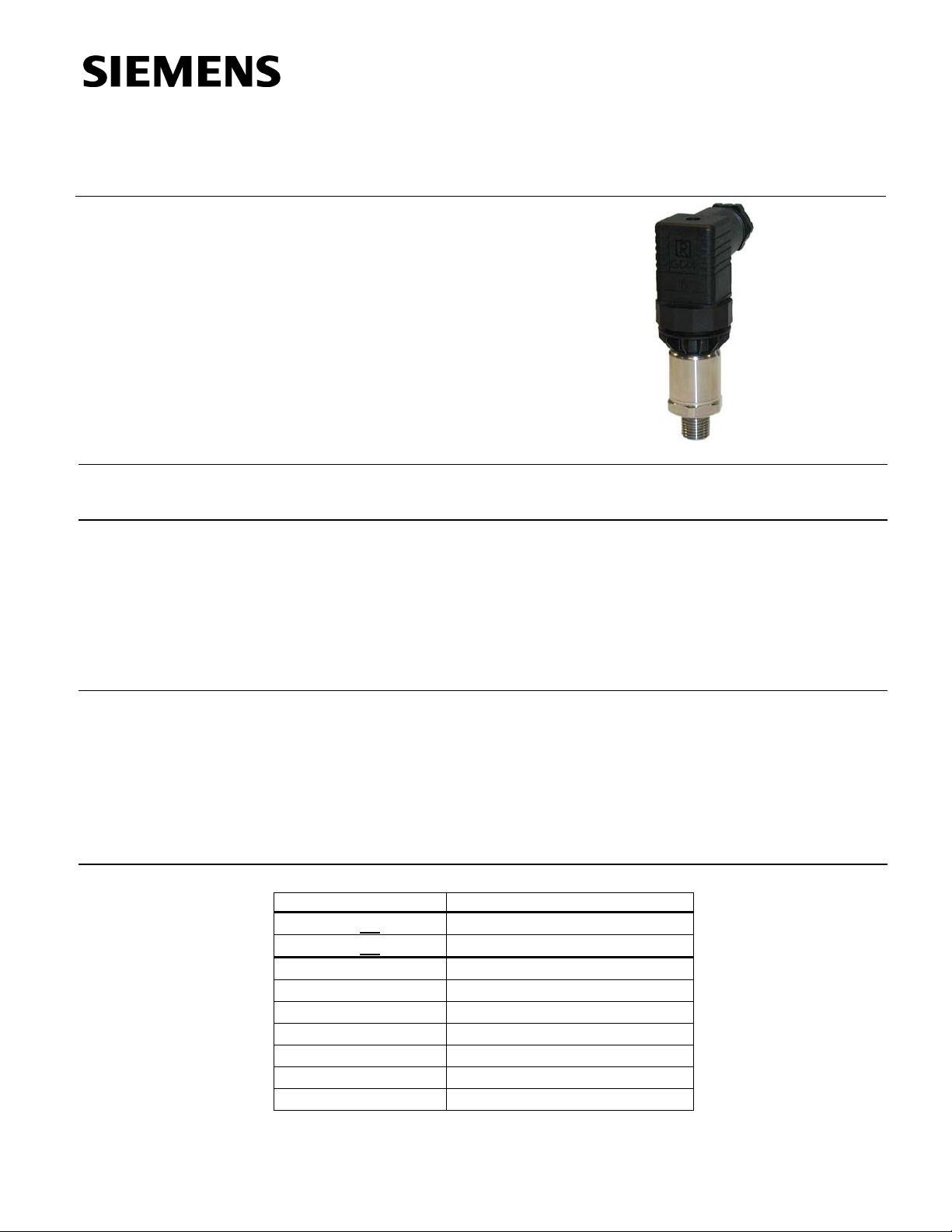
The 7MF15654 Series Pressure Transmitters measure the gauge pressure of
aggressive and non-aggressive gases as well as the level of liquids and vapors.
• High measuring accuracy
• Sturdy stainless steel housing
• For aggressive and non-aggressive media
• Measures the pressure of liquids, gases and vapor
• Temperature-compensated measuring cell
• Compact design
The 7MF15654 Series Pressure Transmitters are mainly used in the U.S. market for the
following industrial areas:
• Chemical industry
• Pharmaceutical industry
• Food industry
• Mechanical engineering
• Water supply
Table 1.
Product Number Description
7MF15654XX005EA1 Sensor, Liquid/Gas, 4 to 20 mA
7MF15654XX105EA1 Sensor, Liquid/Gas, 0 to 10 Vdc
XX = BB 0 to 15 PSI
BE 0 to 30 PSI
BF 0 to 60 PSI
BG 0 to 100 PSI
CA 0 to 150 PSI
CB 0 to 200 PSI
CD 0 to 300 PSI
Siemens Industry, Inc.
Page 2
Technical Instructions 7MF15654 Pressure Transmitter, PSIG Range for Sensing Liquid/Gas
Document Number 155-768
January 18, 2012
Design
Measuring range
<1 bar (<14.5 psi)
Measuring range
> 1 bar (> 14.5 psi)
The design of the pressure transmitter is dependent on the measuring range.
The main components of the pressure transmitter are:
• Stainless steel housing with piezo-resistive silicon measuring cell (with stainless
steel diaphragm, temperature-compensated) and electronics module.
• Stainless steel process connection 1/4 - 18 NPT Straight.
• Electrical connection is made to DIN 43650 with the cable inlet 1/2 – 14 Taper.
Pressure transmitters with a nominal range < 1 bar g (< 14.5 psi g) are available with or
without explosion protection.
The main components of the pressure transmitter are:
• Stainless steel housing with ceramic measuring cell and electronics module. The
temperature-compensated ceramic measuring cell has a thin-film strain gauge
which is mounted on a ceramic diaphragm. The ceramic diaphragm can also be
used for aggressive media.
• Stainless steel process connection 1/4 - 18 NPT Straight.
Electrical connection is made to DIN 43650 with the cable inlet 1/2 – 14 Taper.
Pressure transmitters with a nominal range
> 1 bar g (>14.5 psi g) are available with or
without explosion protection.
Function
Mode of Operation
Measuring range <1 bar
(<14.5 psi)
The pressure transmitter measures the gauge pressure as well as the level of liquids
and gases.
U
const.
p
SEN0444R1
U
I
U
I
1
B0
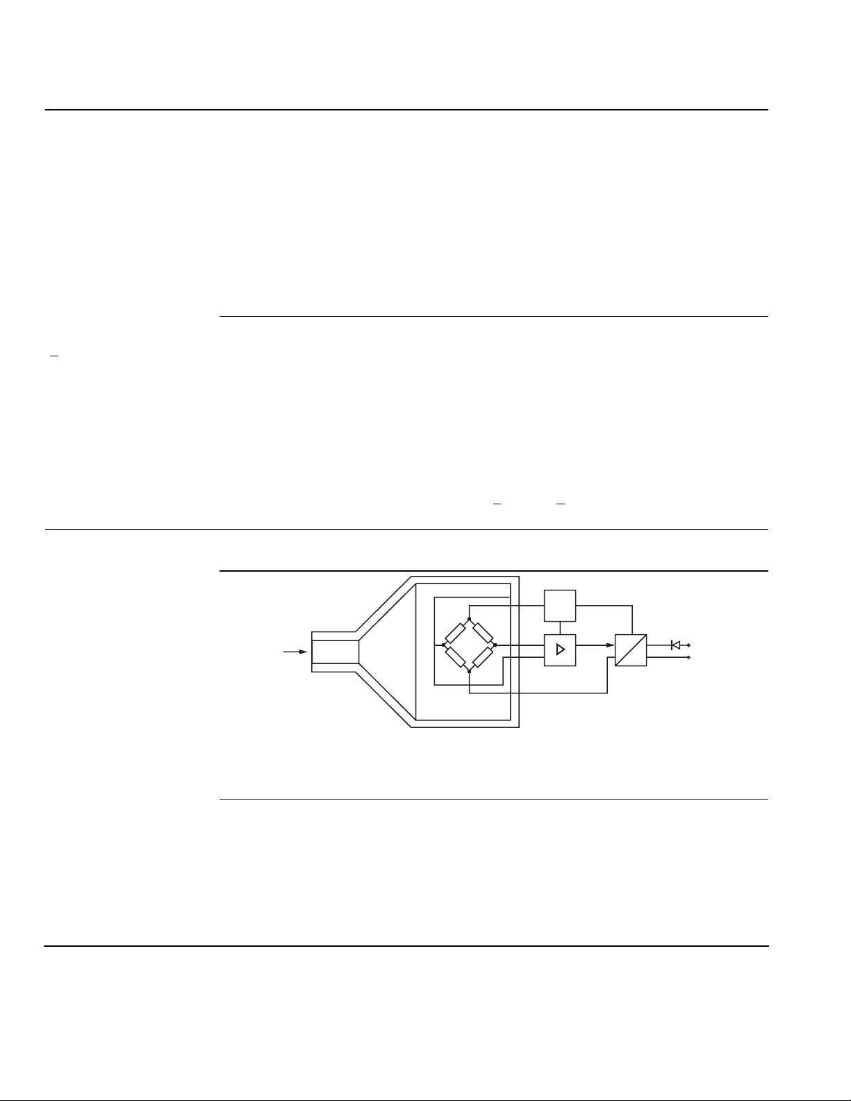
Figure 1. Functional Diagram.
The mode of operation of the pressure transmitter is dependent on the measuring
range.
The silicon measuring cell of the pressure transmitter has a piezo-resistive bridge to
which the operating pressure is transmitted through silicone oil and a stainless steel
diaphragm.
The measuring cell output voltage is fed to an amplifier and converted into a 4 to 20 mA
output current.
The output is linearly proportional to the input pressure.
Page 2 Siemens Industry, Inc.
Page 3

7MF15654 Pressure Transmitter, PSIG Range for Sensing Liquid/Gas Technical Instructions
Document Number 155-768
January 18, 2012
Measuring range ≥1 bar
(≥14.5 psi)
The thin-film measuring cell has a thin-film resistance bridge to which the operating
pressure p is transmitted through a ceramic diaphragm.
The measuring cell output voltage is converted by an amplifier into an output current.
The output is linearly proportional to the input pressure.
Specifications
Mode or Operation
Input Media Range
Output Signal
Accuracy
Rated Operating
Conditions
Design
Input Power Supply U
Measuring range Piezo-resistive
<1 bar (<14.5 psi)
Measuring range Thin-film strain gauge
>1 bar (<14.5 psi)
Measured variable Gauge pressure
Measured range
Pressure 0 to 300 psi g (0 to 21 bar g)
Current output signal 4 to 20 mA
Voltage output signal 0 to 10 Vdc
To EN 60770-1
Error in measurement (at 77°F [25°C]), 0.25% of full-scale value – typical
including conformity error, hysteresis and
repeatability
Response time T
< 0.1 second
99
Long-term drift
Start of scale 0.25% of full scale value/year
Full-scale value 0.25% of full scale value/year
Influence of ambient temperature
Start of scale 0.25%/10 K of full-scale value
Full-scale value 0.25%/10 K of full-scale value
Process temperature -22°F to 248°F (-30°C to 120°C)
Ambient temperature -13°F to 185°F (-25°C to 84°F)
Storage temperature -58°F to 212°F (-50°C to 100°C)
Degree of protection to EN60529 IP65
Weight ≈ 0.55 lb (≈ 0.25 kg)
Wetted parts materials:
Measuring cell
Measuring range < 1 bar (< 14.5 psi) Stainless steel, 1.456 1/316Ti
Measuring range
> 1 bar (> 14.5 psi) AI2O3 – 96%
Process connection Stainless steel, mat. No. 1.4571/316Ti
Gasket Viton
Terminal voltage on pressure transmitter
H
For current output 10 to 36 Vdc
Siemens Industry, Inc. Page 3
Page 4

Technical Instructions 7MF15654 Pressure Transmitter, PSIG Range for Sensing Liquid/Gas
Document Number 155-768
January 18, 2012
Specifications,
Continued
Certificates and
Approvals
Classification according to pressure For gases of fluid group 1 and liquids
equipment directive (DRGL 97/23/EC) of fluid 1; complies with requirements
of article 3, paragraph 3 (sound
engineering practice)
Explosion protection
Intrinsic safety ”i” (only with current output TÜV 02 ATEX 1953X
Identification) Ex II 1/2G EEx ia IIC T4
Intrinsic safety “T.I.S.”(only with current output) Applied
Lloyd’s Register of Shipping Certificate No. 03/30003
Wiring Diagram
Dimensions
I
Output current
0
U
Power supply
B
R
Load
L
Connections:
1 (-UB)
2 (-UB)
U
Output current
0
U
Power supply
B
R
Load
L
Connections:
1 (+UB)
2 (-UB)
3 (U0)
Signal
Signal
SEN0446R1
1+
2-
1+
3+
2-
I
0
U
0
+
U
R
L
R
L
B
+
U
B
Figure 2. Wiring Diagram with Current Output (Top) and Voltage Output
(Bottom).
Figure 3. Dimensions in Millimeters (Inches).
Information in this publication is based on current specifications. The company reserves the right to make changes in specifications and models as
design improvements are introduced. Product or company names mentioned herein may be the trademarks of their respective owners.
© 2012 Siemens Industry, Inc.
Siemens Industry, Inc.
Building Technologies Division
1000 Deerfield Parkway
Buffalo Grove, IL 60089
USA
+ 1 847-215-1000
Your feedback is important to us. If you have
comments about this document, please send them to
SBT_technical.editor.us.sbt@siemens.com
Document No. 155-768
Printed in the USA
Page 4
 Loading...