

Page 1
Pneumatics
Powerstar Single Setpoint
Pneumatic Room Thermostat
192 S
Thermostats
Description
Providing proportional single output, single setpoint,
1-pipe for low air capacity or 2-pipe for high air capacity
pneumatic room temperature control, the 192 S Powerstar
Single Setpoint Pneumatic Room Thermostat is the most
economical model. Refer to the Retroline
page F-15 to replace competitive models.
®
Retrostats on
Features
• Single setpoint dial available in Fahrenheit or
Celsius scales
• Available in direct or reverse acting models
• Sensitive bimetal responds to temperature changes
• Integral, eld adjustable limit stops
• Wall mounting plate for connection to a variety of
rough-in terminal boxes included
• Large volume air capacity relay in 2-pipe models only
• Test port for fast check of output pressure without
removing the cover
• Field replaceable thermometer, setpoint dial, restrictor
and lters for decreased maintenance cost
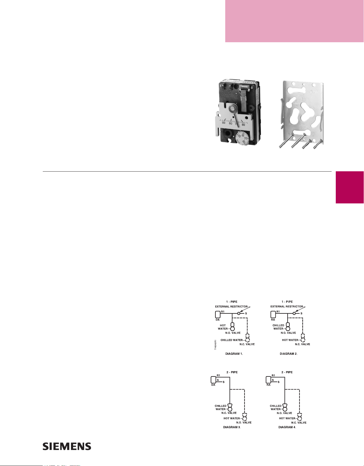
192 S Thermostat chassis.
Typical wall plate and screws.
Applications
Designed for heating and cooling applications for control
of pneumatic valves and damper actuators. The 192 S
Powerstar Single Setpoint Pneumatic Room Thermostat is
excellent for commercial and institutional facilities.
Recommendation
1-pipe: Use when limited output air capacity is required to
operate a single valve and/or actuator; requires external
restrictor, 20 scim (5.4 ml/s) air supply.
2-pipe: Use for high output capacity for control of multiple
valves and actuators, used with or without high/low
limiting controls.
Application Drawings
Dotted lines are alternative control schemes.
F-5
Options
• Quick-connect air connections for ease of installation
and service
• Fixed limit stops to meet government specications
• Large, 1/2" setpoint knob for convalescent homes
Page 2
192 S Thermostat Specifications
For complete conversion kits, refer to the
Retroline® Retrostats starting on page F-15.
F-6
Scale; Range
Major (minor) Divisions............................................. 45 to 85°F, 10(2)°F
(7 to 30°C, 5(1)°C)
Factory Calibration .......................................................72°F, 7.5 psi ±0.3
(22°C, 52 kPa @ 1.8)
Sensitivity Adjustment Range .................1 to 4 psi/°F (12 to 50 kPa/°C)
Factory Setting ......................................................2.5 psi/°F (31 kPa/°C)
Limit Stop
Field Adjustment Range .............................................. 45/85°F (7/30°C)
Fixed Limit Stop Range ............................................. 55/75°F (13/24°C)
Temperature
Storage ......................................................-10 to +140°F (-23 to +60°C)
Ambient Operating ........................................... 40 to 140°F (4 to 60°C)
Accuracy at Factory
Calibration ........................................................................ ±2°F (±1.1°C)
Response ........................................................................ 0.1°F (0.06°C)
Supply Air Pressure
Recommended ............................................................. 25 psi (172 kPa)
Maximum ...................................................................... 30 psi (207 kPa)
192 S Thermostat Product Ordering
Thermostat Chassis Type
Model #
192 S
1-pipe
192 S
2-pipe
Output Setpoint Air Output Capacity
Single Single (Heat or Cool) Low (No Relay)
Single Single (Heat or Cool) High (Integral Relay)
Nominal Air Consumption for Air Compressor Sizing
1-pipe ......................................................................... 25 scim (6.8 ml/s)
2-pipe ......................................................................... 20 scim (5.5 ml/s)
Nominal Air Capacity for Air Main Sizing
1-pipe ......................................................................... 25 scim (6.8 ml/s)
2-pipe ......................................................................... 20 scim (5.5 ml/s)
Nominal Chassis Air Capacity
1-pipe Supply ............................................................. 25 scim (6.8 ml/s)
2-pipe Supply ............................................................ 230 scim (63 ml/s)
1-pipe Exhaust .............................................................. 30 scim (8 ml/s)
2-pipe Exhaust .......................................................... 150 scim (41 ml/s)
Air Connections ..................................................5/32" (4 mm) OD tubing
Dimensions (with cover) ............................. 2.16" W x 3.34" H x 1.59" D
(55 mm W x 85 mm H x 40 mm D)
Shipping Weights (with cover)
Thermostat Chassis and Wall Plate .............................0.53 lb. (0.24 kg)
Plastic Cover/Metal Cover ................0.07 lb. (0.04 kg)/0.27 lb. (0.12 kg)
Thermostat Chassis
& Wall Plate
Thermometer &
Setpoint Scales
°F
°C
°F
°C
Control Action
Direct Reverse
192-200 192-201
192-220 192-221
192-202 192-203
192-222 192-223
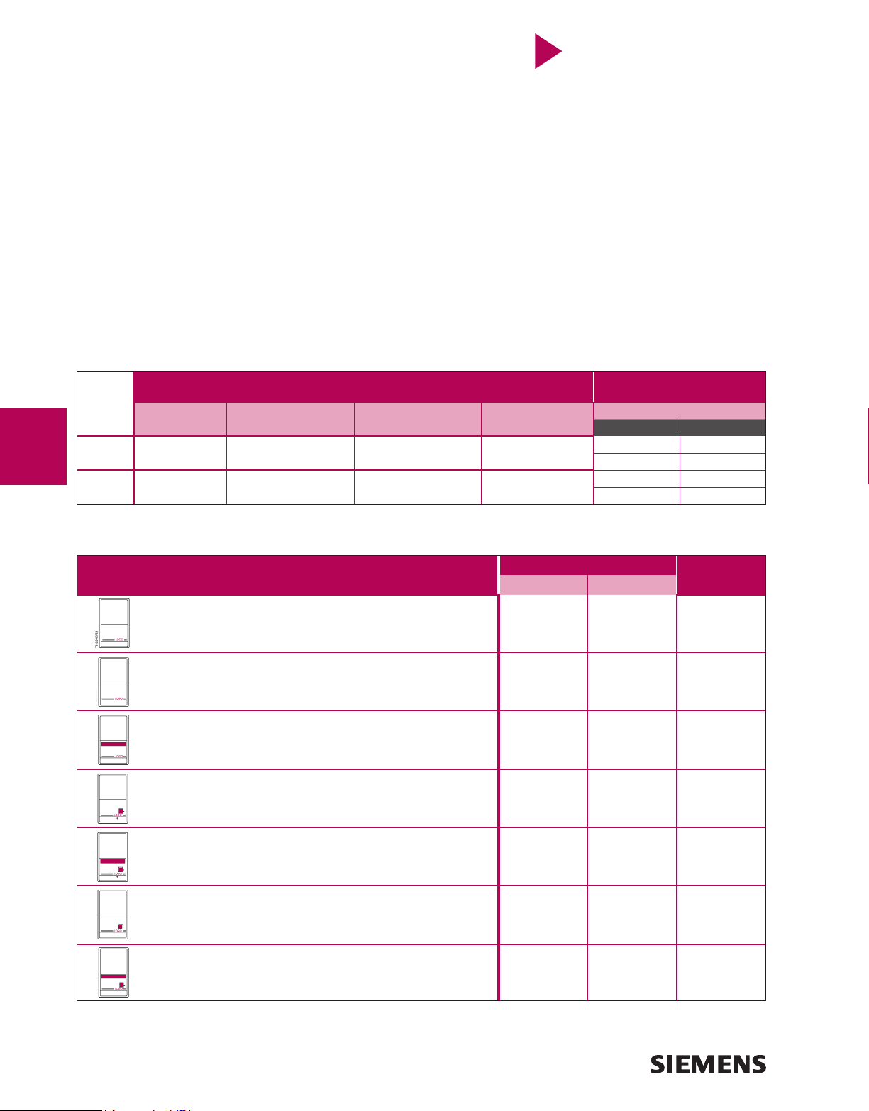
Thermostat Covers (Sold Separately)
Pneumatics
• Adjustment setpoint concealed
• Indicator setpoint concealed
• Chassis thermometer concealed
• No logo
• Adjustment setpoint concealed
• Indicator setpoint concealed
• Chassis thermometer concealed
• With logo
• Adjustment setpoint concealed
• Indicator setpoint concealed
• Chassis thermometer exposed
• Adjustment setpoint key
• Indicator setpoint exposed
• Chassis thermometer concealed
• Use with 1/2" setpoint knob option
•Adjustment setpoint key
•Indicator setpoint exposed
•Chassis thermometer exposed
•Use with 1/2" setpoint knob option
• Adjustment setpoint exposed
• Indicator setpoint exposed
• Chassis thermometer concealed
• Adjustment setpoint exposed
• Indicator setpoint exposed
• Chassis thermometer concealed
Plastic Part No. Metal Part No.
Desert Beige White
192-257 192-257W 192-357
192-256 192-256W 192-356
192-254 192-254W 192-354
192-265 192-265W 192-365
192-266 192-266W 192-366
192-250 192-250W 192-350
192-252 192-252W 192-352
Note: • “Exposed features” are indicated in red on corresponding illustration.
• Universal Cover sold on page F-83. For 194 refer to Powerstar Retroline section.
 Loading...