


WIRELESS MESH
GATEWAY PULSE | PHASE
User Manual


Table of contents
English
1 Overview ................................................................................................................... 4
1.1 General ...................................................................................................................... 4
1.2 Delivery contents ....................................................................................................... 4
1.3 Power supply ............................................................................................................. 4
1.4 Application field ........................................................................................................ 5
2 Layout and connections ............................................................................................ 6
2.1 Dimensions ................................................................................................................ 6
2.2 Connections and displays ......................................................................................... 6
2.2.1 Possible states of the LEDs ............................................................................... 7
2.3 Pin allocation ............................................................................................................. 7
2.3.1 Power, digital output – plug-in connector ........................................................ 7
2.3.2 Ethernet socket RJ45 ......................................................................................... 8
2.3.2.1 Connection socket Amphenol LTW RCP-5SPFFH-TCU7001 ............................... 8
Matching plug: RJ45 connector Amphenol LTW PCP-00AMMA-TLM7001 ........................ 8
3 Installation, initial start-up, safety ........................................................................... 9
3.1 General information .................................................................................................. 9
3.2 Installation ................................................................................................................ 9
3.3 Connecting the cables ............................................................................................... 9
3.3.1 Power supply .................................................................................................. 10
3.3.2 Ethernet .......................................................................................................... 10
3.4 Operation ................................................................................................................. 10
3.5 Cleaning and maintenance ...................................................................................... 10
4 Troubleshooting ..................................................................................................... 11
4.1 General errors .......................................................................................................... 11
5 Technical data ......................................................................................................... 12
5.1 Connectors and power supply ................................................................................. 12
5.2 Ethernet ................................................................................................................... 12
5.3 Radio ........................................................................................................................ 13
5.4 Environment ............................................................................................................ 13
6 Declaration of Conformity ....................................................................................... 14
20180412-6032502-UM
3
EN

1 Overview
1.1 General
The WIRELESS MESH GATEWAY PULSE | PAHSE represents, like the WIRELESS MESH ANCHOR
PULSE | PAHSE, a basing point for the localization within the WIRELESS LOCATION SYSTEM. The
gateway can be connected to the local IT-infrastructure via Ethernet. Through this connection the
nodes (anchors and gateways) will exchange the localization data gathered as well as customer
specific data between the localization network and the localization server. It is suggested to deploy several gateways for larger localization networks in order to raise the number of locatable
TAGs and to enhance the availability of the position information.
1.2 Delivery contents
1 WIRELESS MESH GATEWAY PULSE | PAHSE, Order No. 6032502
Optional Accessories
1 power cord (3-pole), 3 m, Bulgin 400 Series Buccaneer® PX0410/03S
3 fixing screws
Ethernet Connection - Amphenol LTW RCP-00AMMA-TLM7001 with 30 m Ethernet cable
Quick installation guide including drilling template
1.3 Power supply
The WIRELESS MESH GATEWAY PULSE | PAHSE can be operated with 8 to 30 V direct current (DC)
voltage.
The power supply for the device should not exceed the following values:
U < 30V; I<3,3A; P<100W
EN
The device can be supplied via power connector or Ethernet (PoE), not both at the same time. The
device is a class 0 PoE-Device.
4
20180412-6032502-UM

Application field
1.4
The WIRELESS MESH GATEWAY PULSE | PAHSE has been designed for operation in humid environments. For that reason, it is absolutely necessary that all connections are made using waterproof
plugs according to the technical specifications described below and to prevent the ingression of
moisture into the device by using the appropriate sealing caps.
Important information for use in the USA:
This equipment may only be operated indoors. Operation outdoors is in violation of 47
U.S.C. 301 and could subject the operator to serious legal penalties.
This equipment has been tested and found to comply with the limits for a Class A digital
device, pursuant to part 15 of the FCC Rules. These limits are designed to provide reasonable protection against harmful interference when the equipment is operated in a commercial environment. This equipment generates, uses, and can radiate radio frequency
energy and, if not installed and used in accordance with the instruction manual, may
cause harmful interference to radio communications. Operation of this equipment in a residential area is likely to cause harmful interference in which case the user will be required
to correct the interference at his own expense.
This device complies with Part 15 of the FCC rules.
Operation is subject to the following two conditions:
(1) this device may not cause harmful interference, and
(2) this device must accept any interference received, including interference that may
cause undesired operation.
Changes modifications or made to this equipment not expressly approved by Agilion
GmbH may void the FCC authorization to operate this equipment.
This equipment complies with FCC radiation exposure limits set forth for an uncontrolled
environment. This equipment should be installed and operated with minimum distance of
20 cm between the radiator and your body.
20180412-6032502-UM
5
EN
2 Layout and connections
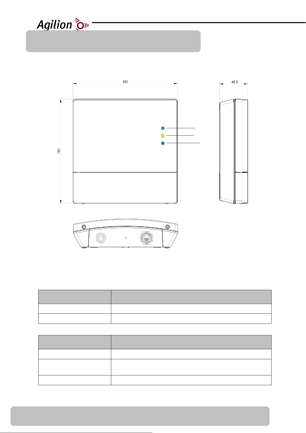
2.1 Dimensions
Power
Radio
Network
Power Venting Ethernet
2.2 Connections and displays
Connection Description
Power Electricity supply
Ethernet RJ45 Ethernet with PoE, Amphenol LTW RCP-00AMMA-TLM7001
Display Description
Power LED (green/red) LED signaling electricity supply
EN
Radio LED (yellow)
Network LED (blue) LED signaling connection to the local IT-network
6
LED signaling the activity of the WLS (sending and receiving radio
signals)
20180412-6032502-UM

GND
2.2.1 Possible states of the LEDs
Power LED status display
(green/red)
On (green) Power supply via cord
Flashes red every second Undervoltage
Radio LED status display
(yellow)
Off Device’s WLS radio disabled
Flashes Device’s WLS radio active
Network LED status display
(blue)
On Network connection established via LAN (Ethernet)
Flashes every scond
Off No network connection established
Description
Description
Description
Network connection established but no connection to the
WIRELESS LOCATION Server
2.3 Pin allocation
2.3.1 Power, digital output – plug-in connector
Power
3-pole connector Buccaneer® PX0412/03P
Pins: SA3350/1
Sealing cap: PX0480
Digital output
Pin Description
1 - Power (red) 8 to 30 V DC
2 - GND (black) Ground
3 - Digital output
20180412-6032502-UM
(brown)
Switched input voltage, maximum current (I) 200 mA
7
EN

2.3.2 Ethernet socket RJ45
The WIRELESS MESH GATEWAY PULSE | PAHSE may only be connected to the Ethernet using the
connectors depicted below. Make sure the twist-lock plugs are locked accurately when connecting the Ethernet cable.
2.3.2.1 Connection socket Amphenol LTW RCP-5SPFFH-TCU7001
Matching plug: RJ45 connector Amphenol LTW PCP-00AMMA-TLM7001
EN
8
20180412-6032502-UM

3 Installation, initial start-up, safety
3.1 General information
The devices can only be used in combination with the WIRELESS LOCATION SYSTEM.
Buildup, installation as well as the use of the tools and clients of the localization system
are described in the corresponding guides and manuals.
3.2 Installation
Carefully read ALL items listed in section 3 (Installation, initial start-up, safety) before in-
stalling the devices in order to safeguard correct installation and operation.
The WIRELESS MESH GATEWAY PULSE | PAHSE is destined for fixed installation onto walls
or ceilings.
The installation has to be carried out by appropriately qualified and trained personnel and
according to the installation guide.
Follow the references concerning the surrounding conditions when installing and operat-
ing the devices.
Make sure that all screws are screwed tightly to the wall/ceiling and that they are able to
carry the weight of device and wiring.
The ambient temperature must not exceed 50° C. Avoid installing devices at locations ex-
posed to direct sunlight.
The installation of the devices has to be carried out according to the applicable provisions
for the installation of electrical systems and utilities. The devices have to be fitted accessible (to open the housing cover) for later maintenance.
3.3 Connecting the cables
Make sure the twist-lock plugs are locked into place correctly to prevent the ingression of
moisture.
Make sure that any wiring has been carried out correctly before the start-up of the device.
Use solely wiring as described in the manual, enclosed with the device or specified ac-
cordingly. Agilion GmbH is not liable for any damages or impairment of functionality resulting from the use of other cables.
Warning: Insofar as any connectors are not in use, they have to be sealed with the appropriate
caps. The caps are attached to the device.
20180412-6032502-UM
9
EN

3.3.1 Power supply
When connecting the power supply to the power connector, all LEDs flash for an instant.
The power LED is on, if power is supplied (cf. states of the LEDs 2.2.1).
The device can be powered via Ethernet cable. In this case the power supply connector
should be sealed to avoid ingress of moisture.
Do not supply the device by power input and PoE at the same time.
Check whether the nominal voltage of the power supply is in accordance with the values
stated in section “Technical data” (cf. 5).
The power supply for the device should not exceed the following values:
U < 30V; I<3,3A; P<100W
3.3.2 Ethernet
Mind the relevant general conditions and their legal basis when installing and connecting
the Ethernet line.
Connect the Ethernet cable to the appropriate socket. Assemble the Ethernet cable into
the RJ45 jack beforehand.
To supply the device Power over Ethernet (PoE) an appropriate infrastructure such as PoE-
Iniector or PoE-Switch is necessary.
3.4 Operation
The device is not designed for use in EX-zones.
Operation of the system in accordance with regulation EN 60950-1 is only safeguarded in-
sofar as the case-cover is mounted (cooling, fire protection, disturbance suppression).
Break the circuit connecting the device in case of emergencies (e.g. damaged housing, in-
trusion of liquids or foreign objects) and notify the service immediately.
3.5 Cleaning and maintenance
EN
The device may only be opened by appropriately trained and qualified personnel.
Repairs may exclusively be carried out by authorized service points.
Unauthorized opening and improper repairs of the device can cause substantial dangers
for the user.
Agilion GmbH’s warranty and liability are void in case of unauthorized opening of the de-
vice.
Never use abrasive, alkaline or aggressive cleaning agents or auxiliary devices when
cleaning the housing.
10
20180412-6032502-UM

4 Troubleshooting
4.1 General errors
Fault detection Cause of error Troubleshooting
WIRELESS module does not
react, all LEDs are off
Power LED (red) flashes
every second
Radio LED (yellow) is off No connection to the WLS Activate localization network
Network LED (blue) is off
Module is not connected or
power supply is not switched
on.
Undervoltage Check power supply
No network connection
established (LAN)
Check module’s power supply
Check local IT network, check
firewall
20180412-6032502-UM
11
EN

5 Technical data
5.1 Connectors and power supply
Connectors and power supply
Voltage 8 to 30 V DC, nominal 24 V DC
Power consumption 9 W
Power connector
Ethernet
3-pole plug-in connector with screw terminal Bulgin Buccaneer®
PX0412/03P
RJ45 Ethernet via connector socket Amphenol LTW RCP-5SPFFHTCU7001
Matching plug: Amphenol LTW PCP-00AMMA-TLM7001
5.2 Ethernet
Ethernet
Ethernet 10/100MBit auto-detect
Duplex mode Half- or full-duplex
DHCP Yes
PoE IEEE 802.3af
class 0, power level 0,44 - 12,94 W
EN
12
20180412-6032502-UM

5.3 Radio
Radio - PULSE
Wireless technology IEEE 802.15.4-2011 UWB
Operating frequency 3100 MHz - 4800 MHz
6000 MHz - 7000 MHz
Output power 0,037 mW (-41,3 dBm/MHz)
Antennas UWB-Antenna Built-in
Radio – PHASE
Wireless technology IEEE 802.15.4
Operating frequency 2,40 bis 2,48 GHz ISM-Band
Bandwidth 2 MHz; Data transmission at 802.15.4 , channels selectable
Output power 100mW
Antennas 2,4 GHz Antenna Built-in
5.4 Environment
Environment and dimensions
Case Plastic housing, Luran® S KR (ASA+PC),
IP 65, UV-resistant
Installation Fixed installation onto walls or ceilings
Dimension 180 x 180 x 48 mm
Weight Approx. 650 g
Temperature range -15 to +50°C
20180412-6032502-UM
13
EN

6 Declaration of Conformity
The Agilion GmbH declares as from 30.11.2017 the conformity of the
WIRELESS MESH GATEWAY PULSE | PHASE
according to the requirements of the standards:
EN 300 328 V2.1.1
EN 62311:2008
EN 302 065-2 V2.1.1
EN 301 489-1 V2.2.0 2017-03
EN 301 489-17 V3.2.0 2017-03
EN 301 489-33 V2.2.0 2017-03
EN 62368-1:2014
and complies with the EC-directives:
1999/519/EC
2014/35/EC
2011/65/EC (RoHS)
2014/30/EC
This declaration applies to all devices bearing the symbol. Validity is lost if modifications are
made to the product.
The WIRELESS MESH GATEWAY PULSE | PAHSE underlies the 2012/19/EC and must be disposed
separate form municipal waste.
EN
Dipl.-Inf. Sven Sieber Dipl.-Kfm.(FH) Andreas Werner
(Managing Director) (Managing Director)
14
20180412-6032502-UM

Agilion GmbH
Blankenauer Str. 74
09113 Chemnitz
20180412-6032502-UM
15
EN

Appendix 1 - Quick installation guide
As stated below you will find a quick installation guide as it is delivered with each WIRELESS
MESH GATEWAY PULSE | PHASE.
3x 3x 1x 1x 1x
1
3x
4
3x
2
130
142
5
3
6
7
130
142
5mm
20170315-Drilling template MESH
not included in Anchor
black = GND
red = Power
brown = digital out
EN
16
20180412-6032502-UM

Notes:
Agilion GmbH

Blankenauer Straße 74
09113 Chemnitz
Germany
Tel.: +49 - (0)371 - 45 00 48-0
Fax.: +49 - (0)371 - 45 00 48-11
www.agilion.de
service@agilion.de
Management:
Sven Sieber
Andreas Werner
HR B 21249 Chemnitz
USt.-IdNr.: DE236591552
 Loading...