


Siemens Aktiengesellschaft 6021112 Users Manual

WIRELESS THR ANCHOR
UserManual
Benutzerhandbuch

FCC ID: SCF6021112
This device complies with part 15 of the FCC Rules.
Operation is subject to the following two conditions: (1) This device may not cause harmful interference, and (2) this device must accept any interference received, including interference that may cause
undesired operation.
Modifications not expressly approved by this company could void the user's authority to operate the
equipment.
Note: This equipment has been tested and found to comply with the limits for a Class A digital device, pursuant to part 15 of the FCC Rules. These limits are designed to provide reasonable protec-
tion against harmful interference when the equipment is operated in a commercial environment. This
equipment generates, uses, and can radiate radio frequency energy and, if not installed and used in
accordance with the instruction manual, may cause harmful interference to radio communications.
Operation of this equipment in a residential area is likely to cause harmful interference in which case
the user will be required to correct the interference at his own expense.
This device and its antenna must not be co-located or operating in conjunction with any other antenna
or transmitter.
This device has been designed to operate with the antennas listed below, and having a maximum gain
of 6 dB. Antennas not included in this list or having a gain greater than 6 dB are strictly prohibited for
use with this device. The required antenna impedance is 50 ohms.
IC: 10971A-6021112
This device complies with Industry Canada licence-exempt RSS standards.
Operation is subject to the following two conditions: (1) This device may not cause interference, and
(2) this device must accept any interference, including interference that may cause undesired operation of the device.
This device has been designed to operate with the antennas listed below, and having a maximum gain
of 6 dB. Antennas not included in this list or having a gain greater than 6 dB are strictly prohibited for
use with this device. The required antenna impedance is 50 ohms.
Le présent appareil est conforme aux CNR d'Industrie Canada applicables aux appareils radio
exempts de licence.
L'exploitation est autorisée aux deux conditions suivantes : (1) l'appareil ne doit pas produire de
brouillage, et (2) l'utilisateur de l'appareil doit accepter tout brouillage radioélectrique subi, même si le
brouillage est susceptible d'en compromettre le fonctionnement.
Ce dispositif a été conçu pour fonctionner avec les antennes indiquées ci-dessous, et
ayant un gain maximum de 6 dB. Il est strictement interdit d’utiliser les antennes ne figurant pas dans
cette liste ou présentant un gain supérieur à 6 dB avec ce dispositif. L’impédance d’antenne requise
est 50 ohms.
Use the following Agilion Antennas only:
• Omni/4.5dBi/N-M
• Omni/6dBi/N-F/360°

Table of contents
English
1 Scope of delivery .......................................................................................................... 2
2 Functionality ................................................................................................................. 3
3 Layout and Connections ............................................................................................... 4
3.1 Connectors and Indicators........................................................................................ 5
3.2 Pin-Assignment ......................................................................................................... 5
4 Initial operation and installation ................................................................................. 7
5 Troubleshooting ........................................................................................................... 8
5.1 General errors ........................................................................................................... 8
6 Technical data............................................................................................................... 9
7 Declaration of Conformity ........................................................................................... 10
20130325-6021214-UM 1
EN

1 Scope of delivery
• 1 WIRELESS THR ANCHOR
• 1 Power plug (5-pole)
• 1 User manual
2 20130325-6021214-UM EN

2 Functionality
The anchor nodes are fixed at a steady position in the localization network. They are basing points
for positioning and could be used for forwarding of position information as well.
20130325-6021214-UM 3
EN
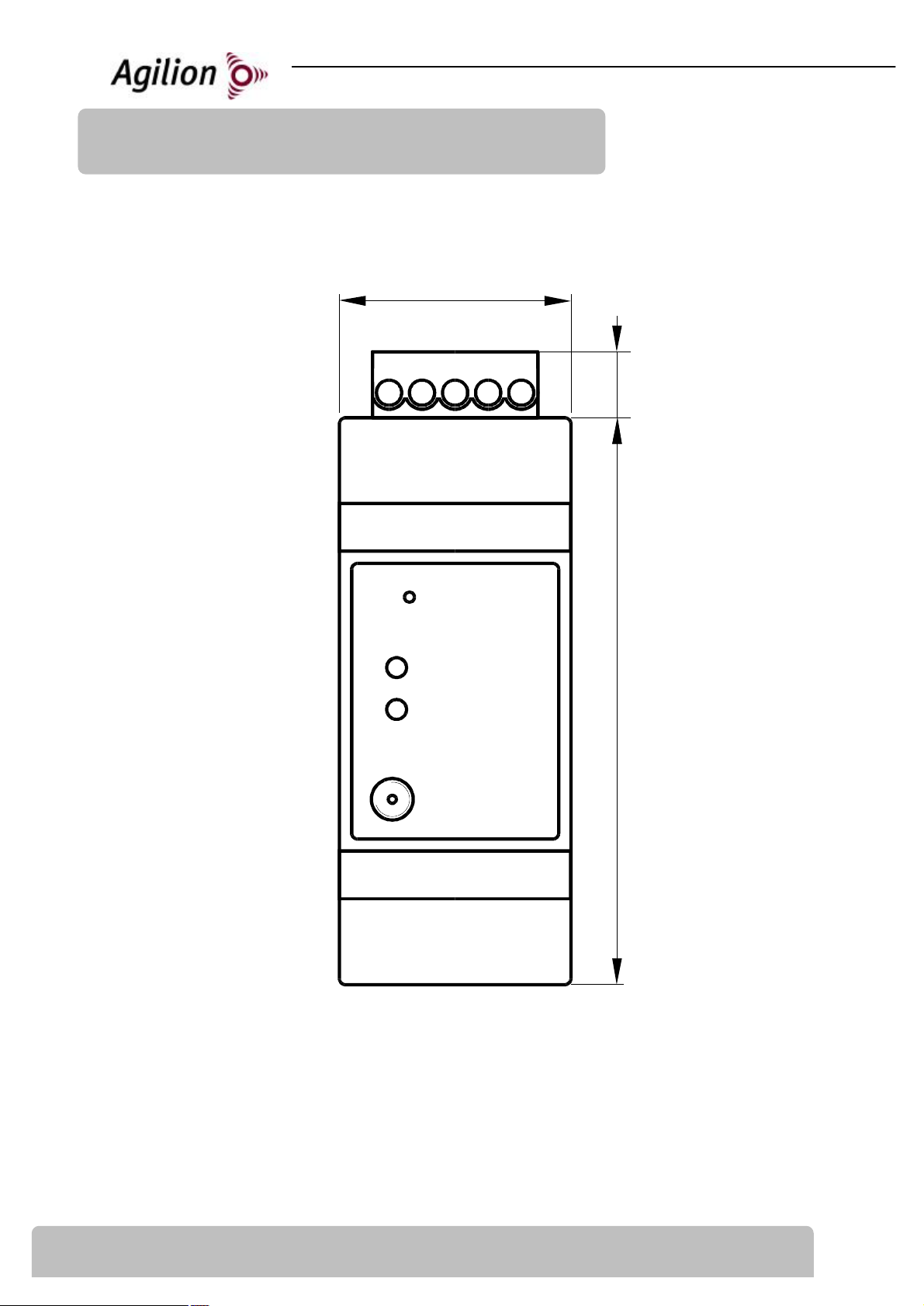
35
mm
3 Layout and Connections
P1
10mm
97 86 10
S1
D2
D1
P3
86mm
4 20130325-6021214-UM EN
3.1 Connectors and Indicators
Connection /Indication Specification
S1 Push Button, Factory Defaults
P1 - POWER Power supply connector
P3 - Antenna RP-SMA antenna connection
D1 - Radio-LED Indication of wireless transmissions
D2 - Power-LED On when running, blinking on error
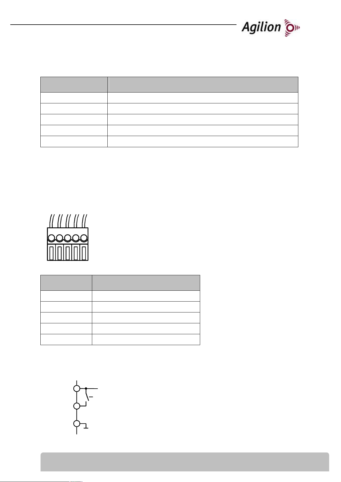
3.2 Pin-Assignment
P1 - POWER - Connector
P1
6 7 8 9 10
5-pole connector with clamping screw
0.13 mm2 to 3.3 mm2
Reorder with order number: 6020154
Pin Description
6 Alarm switsch
7 GND (Ground)
8 GND (Ground)
9 8 to 30 V DC
10 not Used
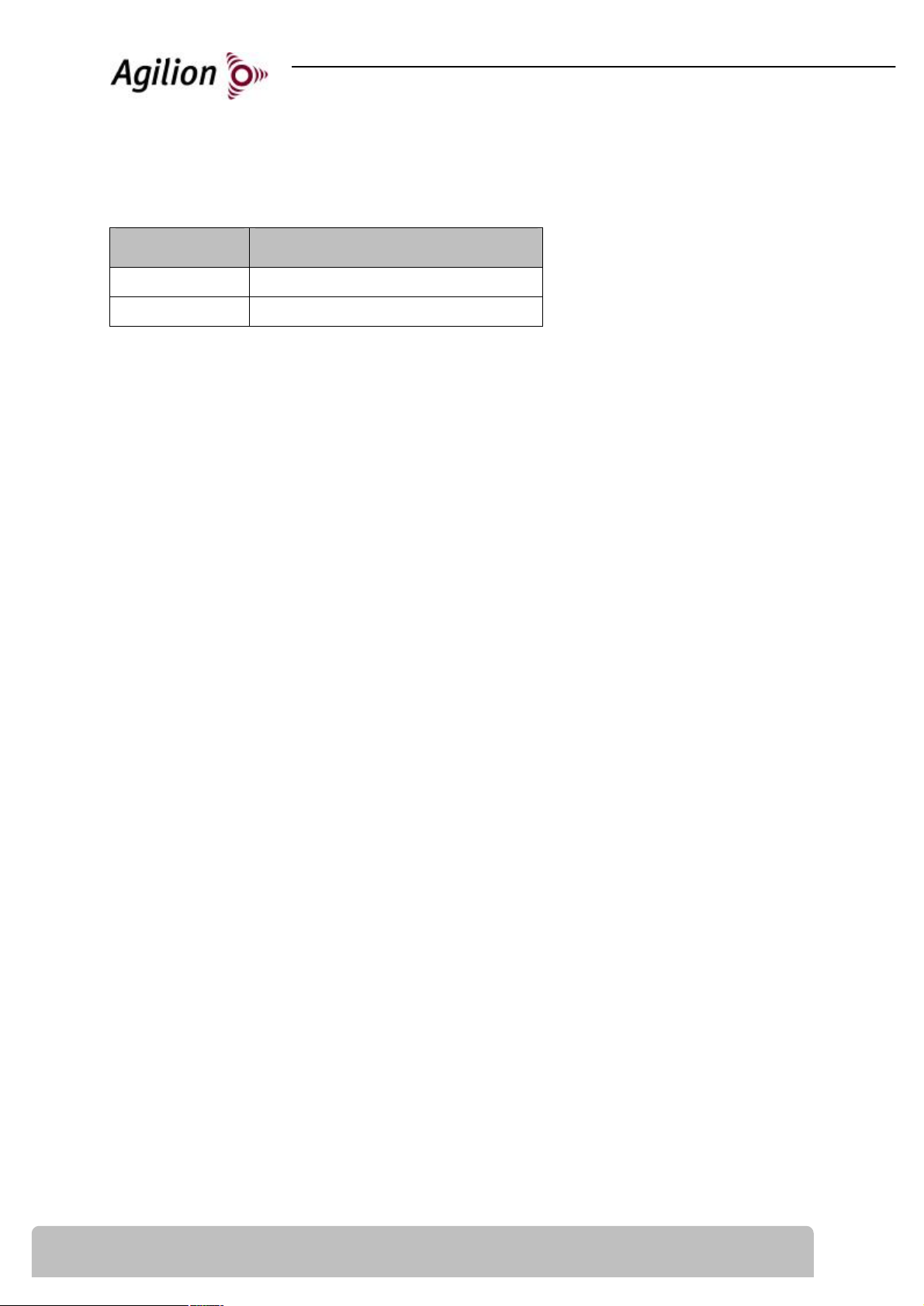
Alarm switch - Pin 6
The high side switch power input Pin 9 to the digital output line Pin 6.
Power Supply
9
9
Output Voltage: 0 (disabled) or Power Input Voltage (enabled)
Alarm Switch
6
6
Maximum Output Current: 100 mA
Ground
8
7
GND
GND
20130325-6021214-UM 5
EN
P3 - Antenna – RP-SMA Connector
Pin Description
1 Antenna
Shield Ground
6 20130325-6021214-UM EN