

Page 1
Gamma instabus
AP 257/31 Wetterstation WS1
AP 257/31 Weather Station WS1
5WG1 257-3AB31
Bedien- und Montageanleitung
Operating and Mounting Instructions
Stand: Februar 2008
As at: February 2008
Bild / Figure 1
Bild / Figure 2
Bild / Figure 3
Bild / Figure 4
Bild / Figure 5
A5E02038557D DS01
D
Produkt- und Funktionsbeschreibung
Die Wetterstation WS1 (siehe Bild 1) enthält in einem kompakten Gehäuse alle Sensoren, die Auswerte-Elektronik und die
Bus-Ankopplung. Sie misst Windgeschwindigkeit, Helligkeit und
Temperatur, erkennt Dämmerung und Niederschlag und empfängt das DCF77-Funksignal für Datum und Zeit. Neben Datum
und Zeit können alle Messwerte im EIS5-Format auf den Bus gesendet und jeweils auf bis zu 3 Grenzwerte überwacht werden.
Grenzwerte können als Parameter oder als Kommunikationsobjekte gewählt werden.
Die Wetterstation ermöglicht nicht nur eine einfache Sonnenschutz-Steuerung, bei der abhängig davon, ob die Sonne
scheint oder nicht, der Sonnenschutz aktiviert bzw. deaktiviert
wird. Darüber hinaus kann eine Sonnenschutz-Steuerung für bis
zu 4 Fassaden unter Berücksichtigung ihrer Ausrichtung (Himmelsrichtung) aktiviert werden. Bei dieser wird der Sonnenschutz einer Fassade nur dann automatisch aktiviert, wenn die
Sonne auch auf die jeweilige Fassade scheint und deaktiviert,
sobald dies nicht mehr möglich ist bzw. die Sonne nicht mehr
scheint.
Über das Parameter-Fenster „Sicherheit“ können neben Windalarm, Frostalarm und Niederschlagsalarm insgesamt bis zu 8
Alarm- oder Störungs-Meldungen über eine logische ODERFunktion zu einem Kommunikationsobjekt „Sicherheit“ verknüpft werden, das im Alarmfall zum Fahren des Sonnenschutzes in seine Sicherheitsstellung führt. Zusätzlich stehen 4 UNDGatter und 4 ODER-Gatter mit je 4 Eingängen für weitere logische Verknüpfungen zur Verfügung.
Zur Parametrierung sollte die Engineering Tool Software ETS3
verwendet werden, da bei ihr die Einstellungs-Menüs der Wetterstation grafisch optimal dargestellt werden.
Die Spannungsversorgung der Elektronik erfolgt über AC 20 V
oder DC 24 V Sicherheits-Kleinspannung (SELV). Zur Übertragung dieser Spannung kann das weiß/gelbe Aderpaar der Busleitung genutzt werden.
Weitere Informationen
http://www.siemens.de/gamma
Technische Daten
Sensorik
•
Windsensor: Messbereich: 0 ... 70 m/s,
Auflösung: < 10% des Messbereichs
• Helligkeitssensor: Messbereich: 0 ... 99.000 Lux,
Auflösung bei: 0 ... 120 Lux 1 Lux
121 ... 1.046 Lux 2 Lux
1.047 ... 52.363 Lux 63 Lux
52.364 ... 99.000 Lux 423 Lux
•
Temperatursensor: Messbereich: - 40 ... + 80 °C,
Auflösung: 0,1 °C
• Regensensor:
Heizung: ca. 1,2 W
Spannungsversorgung
• Busspannung: erfolgt über die Buslinie
• Busstrom: 9 mA
• Sensor-Elektronik: AC 20 V +10%, 50/60 Hz oder
• Leistungsaufnahme: bei AC 20 V: max. 2,2 VA,
Achtung: Beim Einsatz von Schaltnetzteilen kann die Qualität
des DCF77-Empfangs beeinträchtigt werden.
Anschlüsse
• Spannungsversorgung: Steckklemmen für Massivleiter oder
• Busleitung: Busklemme schraubenlos,
Mechanische Daten
Abmessungen: ca. 118 mm x 96 mm x 77 mm (L x B x H)
Gewicht: ca. 145 g
Elektrische Sicherheit
Schutzart (nach EN 60529): IP44
Umweltbedingungen
• Umgebungstemperatur im Betrieb: - 30 ... + 50 °C
• Lagertemperatur: - 20 ... + 70 °C
• rel. Feuchte (nicht kondensierend): 5 ... 93 %
Prüfzeichen
KNX EIB
10%, max. 110 mA, Restwelligkeit < 10%,
DC 24 V +
max. zulässige Leitungslänge 100 m
bei DC 24 V: max. 2,64 W
feindrähtige Leiter 0,5 ... 1,5mm²
0,6... 0,8 mm ∅ eindrähtig, Abisolierlänge 5 mm.
Seite 1 von 2
Product and Applications Description
The weather station WS1 (see figure 1) contains all sensors,
electronic systems for weather data analysis and bus interfacing
in one compact enclosure. It measures wind speed, brightness
and temperature, detects dust / dawn and precipitation and receives the DCF77 radio signal for date and time. Aside from
date and time, all measured values can be sent to the bus in the
EIS5 format and monitored respectively for up to 3 limit values.
Limit values can be selected as parameters or as communication
objects.
The weather station not only allows for a simple sun protection
control which, depending on whether the sun is shining or not,
activates or deactivates the sun protection. It can also activate a
sun protection control for up to 4 façades under consideration
of their alignment (direction of the compass). In this case, the
sun protection of a façade is only automatically activated when
the sun shines on the respective façade and deactivated as soon
as this is no longer possible or the sun is no longer shining.
In the parameter window “Safety”, not only can wind alarm,
frost alarm and precipitation alarm be set up, but up to 8 alarm
or error messages can be combined using a logical OR function
to create a “Safety” communication object, which can bring the
sun protection into its safety position if it is triggered. In addition, 4 AND-gates and 4 OR-gates are available with 4 inputs
each for additional logical combinations.
For configuration, the engineering tool software ETS3 should be
used, since it presents a graphically optimal display of the setting menus of the weather station.
The voltage supply of the electronics takes place via AC 20 V or
DC 24 V safety extra-low voltage (SELV). For the transmission
of this voltage, the white / yellow twisted pair of the bus cable
can be used.
Additional Information
http://www.siemens.com/gamma
Technical Specifications
Sensors
• Wind sensor: Measuring range: 0 ... 70 m/s,
Resolution: < 10% of the measuring range
• Brightness sensor: Measuring range: 0 ... 99.000 lux,
Resolution at: 0 ... 120 lux 1 lux
121 ... 1.046 lux 2 lux
1.047 ... 52.363 lux 63 lux
52.364 ... 99.000 lux 423 lux
• Temperature sensor: Measuring range: - 40 ... + 80 °C,
Resolution: 0.1 °C
• Rain sensor:
Heating: approx. 1.2 W
Voltage supply
• Bus voltage: via the bus line
• Bus current: 9 mA
• Sensor electronics: AC 20 V +10%, 50/60 Hz or
DC 24 V + 10%, max. 110 mA, residual ripple < 10%,
max. permissible cable length 100 m
• Power consumption: at AC 20 V: max. 2.2 VA,
at DC 24 V: max. 2.64 W
Attention: When using a switching power supply, the quality of
the DCF77 reception may be impaired.
Connections
• Voltage supply: plug terminals for solid conductors or finely
stranded conductors 0.5 ... 1.5mm²
• Bus connection: screwless bus terminal,
0.6... 0.8 mm ∅ single-wire, insulation strip length 5 mm.
Mechanical data
Dimensions: approx. 118 mm x 96 mm x 77 mm (L x W x H)
Weight: approx. 145 g
Electric safety
Protection type (according to EN 60529): IP44
Environmental conditions
• Ambient temperature during operation: - 30 ... + 50 °C
• Storage temperature: - 20 ... + 70 °C
• rel. humidity (not condensing): 5 ... 93 %
Markings
KNX EIB
GB
Page 1 of 2
Page 2
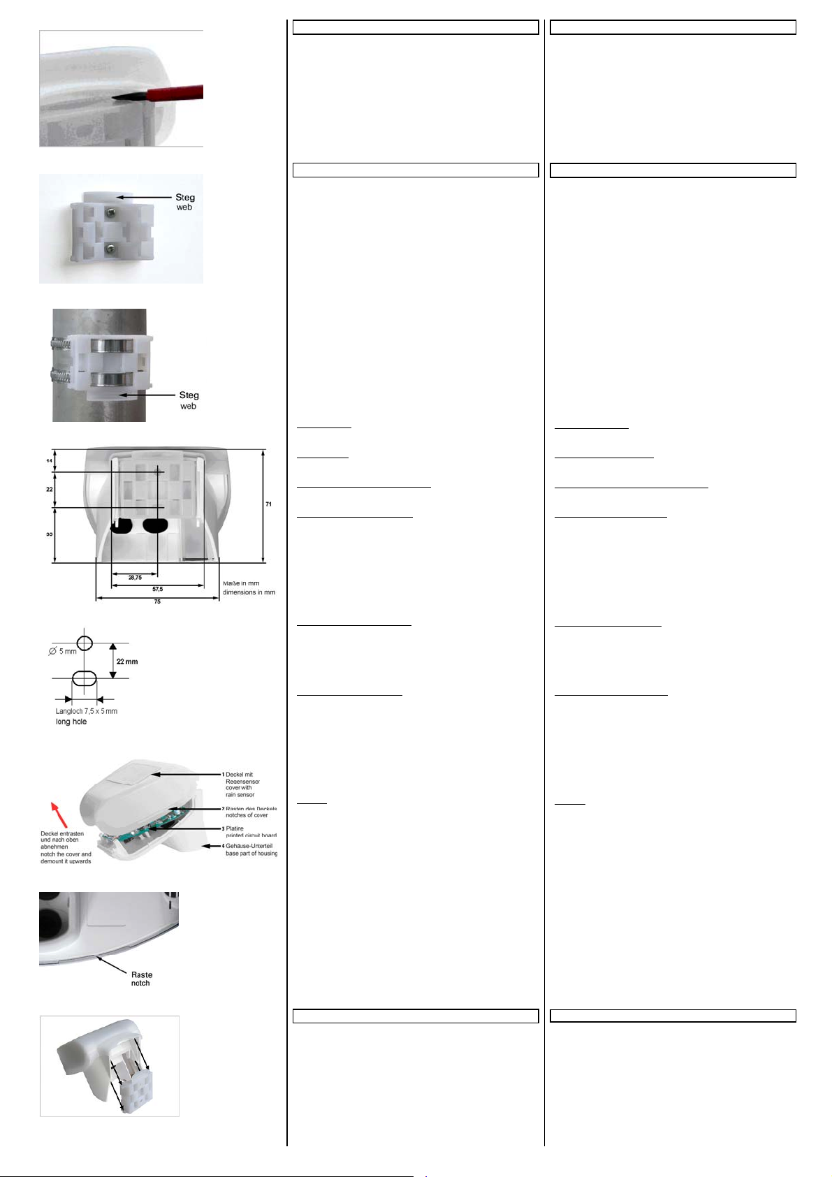
Bild / Figure 6
Bild / Figure 7
Bild / Figure 8
Bild / Figure 9
Bild / Figure 10
Bild / Figure 11
Bild / Figure 12
Bild / Figure 13
A5E02038557D DS01
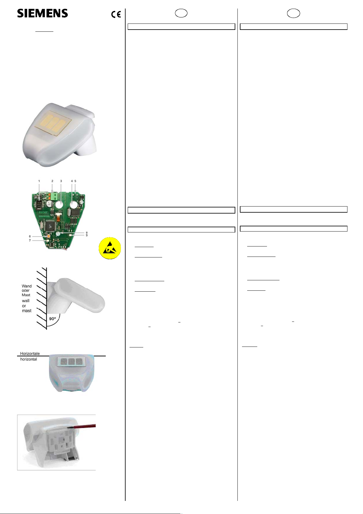
Lage und Funktion der Anzeige- und Bedienelemente
siehe Bild 2
1 Steckplatz für Kabelverbindung zum Niederschlagssensor im
Gehäusedeckel
2 Steckklemme für Spannungsversorgung AC 20 V / DC 24 V
3 Öffnung für Kabel Spannungsversorgung
4 Öffnung für Busleitung
5 Steckplatz für Busklemme
6 Inbetriebnahme-Taste
7 Inbetriebnahme-LED
8 Stellschraube der DCF77-Antenne
9 Kontroll-LED für DCF77-Empfang
Montage und Verdrahtung
Standort
Wählen Sie eine Montageposition am Gebäude, wo Wind, Regen
und Sonne ungehindert von den Sensoren erfasst werden können. Insbesondere darf die Wetterstation nicht durch den Baukörper, Gebäude oder Bäume abgeschattet werden. Unter der
Wetterstation muss mindestens 60 cm Freiraum belassen werden, um eine korrekte Windmessung zu ermöglichen und bei
Schneefall ein Einschneien zu verhindern.
Eisenkonstruktionen oder große Metallflächen direkt hinter
oder in der Nähe der Wetterstation setzen die Empfangsqualität
des eingebauten DCF77-Empfängers herab. Magnetfelder, Sender und Störfelder von elektrischen Verbrauchern können ebenfalls den Empfang des DCF-Signals stören oder unmöglich machen.
Die Wetterstation muss an einem Mast oder einer senkrechten
Wand montiert (siehe Bild 3) und in der Querrichtung horizontal
(waagrecht) ausgerichtet werden (siehe Bild 4).
Montage
Der mitgelieferte kombinierte Wand- / Masthalter ist bei Lieferung an der Gehäuserückseite eingerastet.
Zum Entfernen verwenden Sie bitte einen Schraubendreher und
lösen Sie den Halter rechts und links wie in Bild 5 und 6 gezeigt.
Schieben Sie den Halter nach unten heraus.
Wandmontage:
Befestigen Sie den Halter senkrecht mit der ebenen Seite zur
Wand, den halbmondförmigen Steg nach oben (siehe Bild 7).
Mastmontage:
Befestigen Sie den Halter mit der geschwungenen Seite zum
Mast, Steg nach unten (siehe Bild 8).
Ansicht der Rückwand und Bohrplan:
Abmessungen der Gehäuserückseite mit Halter: siehe Bild 9,
Bohrplan: siehe Bild 10.
Vorbereitung der Wetterstation:
Der Deckel der Wetterstation mit dem Regensensor ist am unteren Rand rechts und links eingerastet. Nehmen Sie den Deckel
von der Wetterstation ab (siehe Bild 11). Gehen Sie sorgfältig
vor, um die Kabelverbindung zwischen der Platine im Unterteil
und dem Regensensor im Deckel nicht abzureißen (Kabel mit
Stecker).
Führen Sie die Busleitung durch die Gummidichtungen an der
Unterseite der Wetterstation und schließen sie die Aderpaare für
Spannungsversorgung und Bus unter Berücksichtigung der Polarität an die dafür vorgesehenen Klemmen an (siehe Bild 2).
Ausrichten der DCF77-Antenne:
Die Antenne für den DCF77-Empfang von Datum und Zeit befinden sich im Gehäuse unter der Platine. Mit der Stellschraube
(siehe Bild 2) kann die Antenne in einem Winkel von 180° gedreht und somit optimal ausgerichtet werden. Der Empfang ist
vorhanden, wenn die Kontroll-LED regelmäßig einmal pro Sekunde blinkt.
Befestigen der Wetterstation
Schließen Sie das Gehäuse, indem Sie den Deckel über das Unterteil stülpen. Der Deckel muss rechts und links mit einem
deutlichen „Klick“ einrasten. Prüfen Sie, ob Deckel und Unterteil
richtig verrastet sind! Bild 12 zeigt die korrekt geschlossene
Wetterstation von unten.
Schieben Sie nun das Gehäuse von oben in den montierten Halter. Die Zapfen des Halters müssen dabei in den Schienen des
Gehäuses einrasten (siehe Bild 13).
Die Wetterstation lässt sich bei Bedarf wieder nach oben aus
dem Halter herausziehen.
Vorsicht:
Öffnen Sie die Wetterstation nicht, wenn Wasser (Regen) eindringen kann. Schon wenige Tropfen könnten die Elektronik beschädigen.
Achten Sie auf korrekten Anschluss. Ein Falschanschluss kann
zur Zerstörung der Elektronik der Wetterstation führen.
Bei der Montage ist darauf zu achten, dass der Temperatursensor (kleine Platine an der Unterseite des Gehäuses) nicht beschädigt wird. Auch die Kabelverbindung zwischen Platine und
Regensensor darf beim Anschluss nicht abgerissen oder geknickt werden. Der Windmesswert wird erstmalig 60 Sekunden
nach Anlegen der Versorgungsspannung übertragen.
Wartung
Die Wetterstation sollte regelmäßig (2x pro Jahr) auf Verschmutzung überprüft und bei Bedarf gereinigt werden. Bei
starker Verschmutzung kann der Windsensor funktionsunfähig werden, eine ständige Regenmeldung anliegen oder keine Sonne mehr erkannt werden.
Zur Wartung und Reinigung sollte die Wetterstation sicherheitshalber immer vom Bus und der Versorgungsspannung
getrennt werden.
Allgemeine Hinweise
• Die Bedienungsanleitung ist dem Kunden auszuhändigen.
• Ein defektes Gerät ist an die zuständige Geschäftsstelle der
Siemens AG zu senden.
• Bei zusätzlichen Fragen zum Produkt wenden Sie sich bitte
an unseren Technical Support:
℡ +49 (0) 180 50 50-222
" +49 (0) 180 50 50-223
! www.siemens.de/automation/support-request
:
Seite 2 von 2
Location and Function of the Display and Operating Elements
see figure 2
1 Slot for cable connection to the precipitation sensor in the lid
of the enclosure
2 Plug terminal for voltage supply AC 20 V / DC 24 V
3 Opening for voltage supply cable
4 Opening for bus cable
5 Slot for bus terminal
6 Commissioning button
7 Commissioning LED
8 Adjusting screw for the DCF77 antenna
9 Control LED for DCF77 reception
Mounting and wiring
Location
Select a position on the building where wind, rain and sunshine
can be recorded by the sensors without impairment. In particular the weather station may not be shadowed by the building,
trees or anything else. There must be at least 60 cm free space
under the weather station to allow for correct wind measurements and to prevent the station being snowed in case of snow.
Iron constructions or large metal surfaces directly behind or
near the weather station will degrade the reception quality of
the installed DCF77 receiver. Magnetic fields, transmitters and
interference fields caused by electric consumer loads can also
interfere with the reception of the DCF signal or make it impossible.
The weather station must be mounted on a mast or a vertical
wall (see fig. 3) and be aligned horizontally across (see fig. 4).
Mounting
The supplied combined wall / mast holder is slotted into the rear
of the enclosure on delivery.
To remove it, please use a screwdriver and remove the holder
on the right and the left, as shown in figs. 5 and 6. Slide the
holder out towards the bottom.
Mounting on a wall:
Fasten the holder vertically with the even side to the wall, with
the crescent-shaped bar to the top (see fig. 7).
Mounting on a mast / pole:
Fasten the holder vertically with the curved side to the mast /
pole and the bar to the bottom (see fig. 8).
View of the rear wall and drilling scheme:
Dimensioning of the rear of the enclosure with holder:
see fig. 9, Drilling scheme: see fig. 10.
Preparing the weather station:
The lid of the weather station with the rain sensor is slotted in
on the right and the left at the lower edge. Remove the lid from
the weather station (see fig. 11). Be careful not to tear open the
cable connection between the circuit board in the bottom part
and the rain sensor in the lid (cable with plug).
Guide the bus connection through the rubber seals at the bottom part of the weather station and connect the cable pairs for
the voltage supply and the bus to the provided terminals while
taking polarity into account (see fig. 2).
Aligning the DCF77 antenna:
The antenna for the DCF77 reception of date and time of day
are under the circuit board inside the enclosure. With the adjusting screw (see fig. 2), the antenna can be rotated at an angle of 180º and thus aligned optimally. Reception is active if the
control LED flashes regularly once a second.
Fastening the weather station:
Close the enclosure by putting the lid over the lower part. The
lid must snap into place on the left and the right with a clear
“click”. Check that the lid and lower part are properly snapped
into place! Fig. 12 shows the correctly closed weather station
from below.
Now slide the enclosure into the mounted holder from above.
The pegs of the holder must slot into the rails of the enclosure
(see fig. 13).
If needed, the weather station can be pulled out of the holder in
an upwards direction.
Caution:
Do not open the weather station if water (rain) can get into the
inside. A few drops are enough to damage the electronics.
Take care that the connections are correctly made. A wrong
connection can destroy the electronics of the weather station.
During assembly care should be taken that the temperature sensor (small circuit board on the lower part of the enclosure) is
not damaged. The cable connection between the circuit board
and the rain sensor may not be torn off or bent while making
the connection.
The wind measurement value is first transmitted 60 seconds after initiating the supply voltage.
Maintenance
The weather station should be regularly checked (twice per
year) for soiling and cleaned if necessary. In case of strong
pollution, the wind sensor may cease to function, rain may
be reported permanently or no more sun may be detected.
During maintenance and cleaning, the weather station
should always be separated from the bus and the supply
voltage for safety purposes.
General Notes
• The operating instructions must be handed over to the client.
• Any faulty devices should be returned to the local Siemens
office.
• If you have further questions concerning the product please
contact our technical support:
℡ +49 (0) 180 50 50-222
" +49 (0) 180 50 50-223
! www.siemens.com/automation/support-request
Page 2 of 2
 Loading...