

Siemens WLTS Application Manual
Application Guide
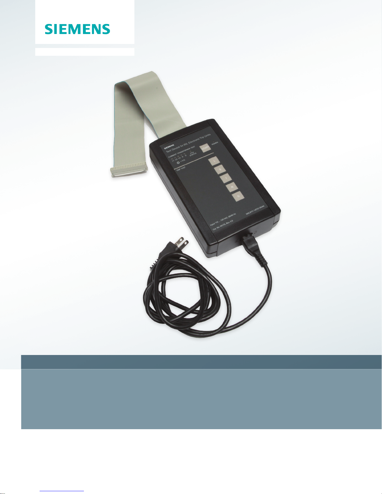
WLTS Hand-Held Test Set
WL Low Voltage Circuit Breakers
www.usa.siemens.com/WLBreaker
Introduction
NOTICE
Erroneous test results may occur when the trip
unit is powered by either:
• Load current
• External 24 vdc control power
All testing should be conducted with the primary
bus de-energized, and external 24 vdc control
power disconnected or turned off.
The WLTS hand-held test unit is the perfect companion for
service personnel and users of Siemens type WL circuit
breakers. It will verify many trip unit functions and, in most
cases, removes the need for primary injection testing.
The WLTS can perform the following functions:
• Verify the continuity of the air-core current sensors
and the energy transducers in each phase of the
circuit breaker.
• Verify connections to external air-core neutral current
sensors in 4-wire residual applications and iron-core
ground CTs (current transformers) in MDGF or other
directly ground-sensed applications.
• Verify the connection from the electronic trip unit and the
tripping solenoid.
• Verify that of each of the main overcurrent protective
functions (long-time, short-time, instantaneous, and
optional ground-fault and neutral overcurrent) will trip
the circuit breaker.
• Help verify communications to an external master by
simulating currents in each of the phases.
By design, the WLTS provides a minimally invasive solution
for circuit breaker testing, allowing maximum up-time. It
allows the operator to quickly determine the health of the
entire trip system, and quickly return the circuit breaker
to service.
The WLTS is the preferred test tool to verify compliance of
the entire trip system of the WL circuit breaker, including the
trip unit, rating plug, trip coil, current sensors, and all
associated wiring.
The WLTS has additional functionality that is beneficial during
startup and commissioning activities.
• The WLTS can be utilized as a temporary power supply
to provide control power for the WL family of trip units
facilitating the programming of the trip unit during
startup and commissioning. The WLTS will supply power
only to the trip unit and display and not any other
connected modules.
• If the circuit breaker includes a COM15 or COM16, the
WLTS can instruct the trip unit to pass along dummy load
data to the communications network, so that
communications between the WL circuit breaker and the
SCADA system can be verified.
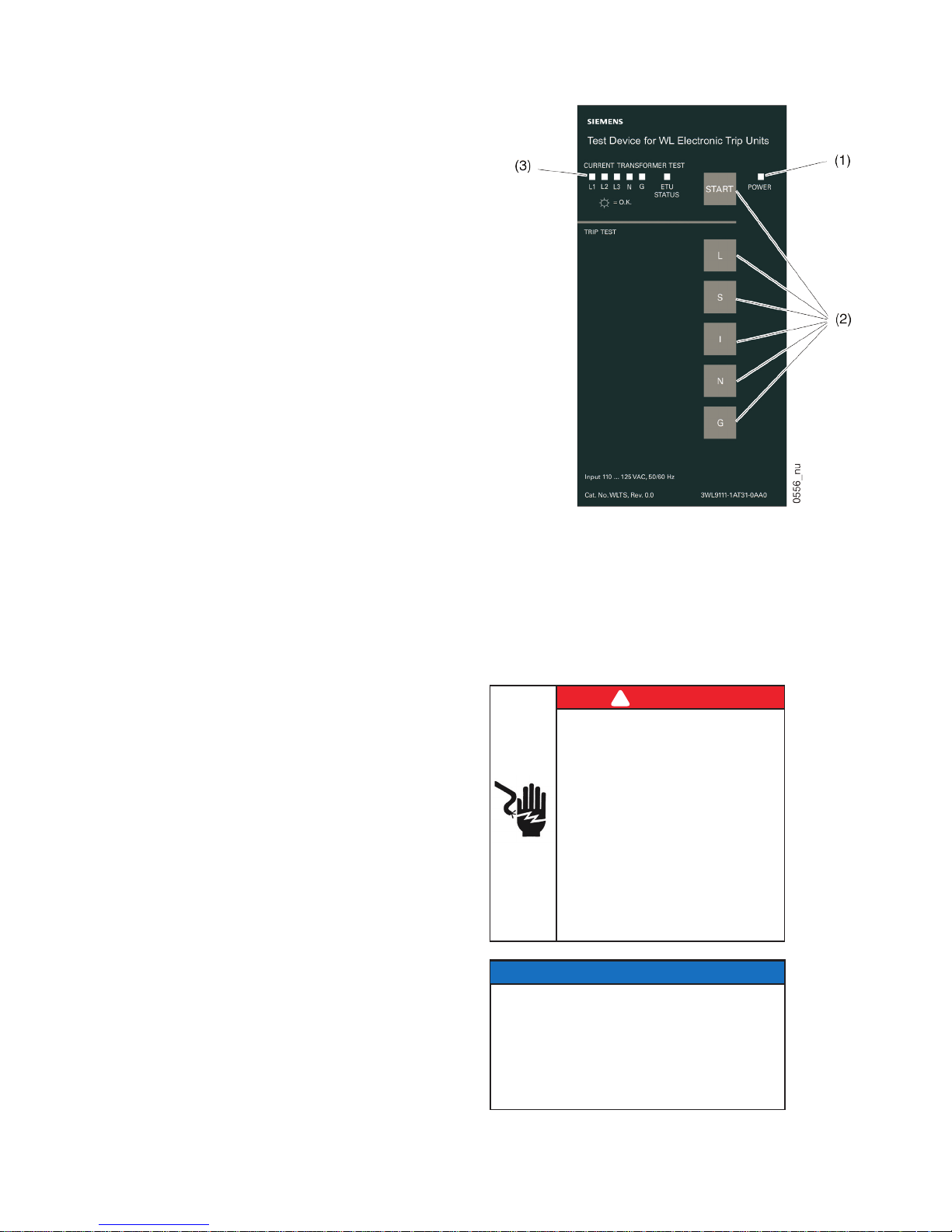
Orientation
(1) Power indicator
(2) Buttons to initiate tests
(3) LEDs to indicate sensor / CT continuity and status
Functional Testing
Preparing to test
!
DANGER
Hazardous Voltage.
Will cause death or serious injury.
Qualified personnel only.
Disconnect and lock off all power before
working on this equipment.
• Always work on de-energized
equipment.
• Always de-energize before
performing any tests, maintenance,
or repair.
• Follow safety related work practices,
as described in NFPA 70E, at all times.
1
Modified Differential Ground Fault System
2
NOTICE
Erroneous test results may occur when the trip
unit is powered by either:
• Load current
• External 24 vdc control power
All testing should be conducted with the primary
bus de-energized, and external 24 vdc control
power disconnected or turned off.
Remove the trip unit cover (Catalog number WLTSC55 or
WLTSC76), if present, and the cover over the X25 test port.
Record the settings of the trip unit and set long time pickup
(IR) to 1.0 x In.
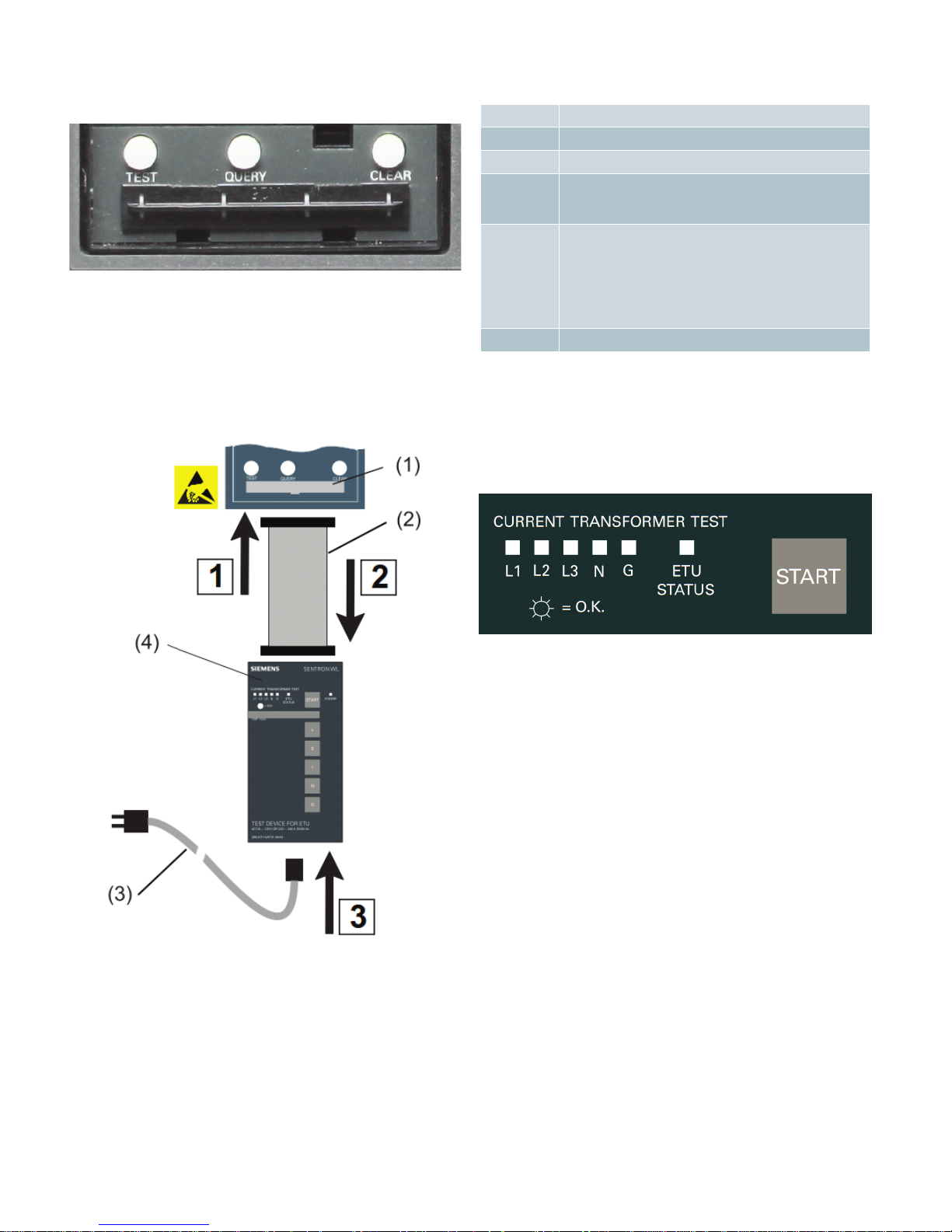
Connecting to the trip unit
1. Plug the ribbon cable into the test port
Table 1
Indicator Definition
1x WLTS in need of repair
2x Trip unit needs replacement
3x Trip unit externally powered
WLTS connected while powered
4x Parameter conflict
Current sensor not connected
Incorrect rating plug
Missing rating plug
5x Tripping solenoid not connected
1
2. Plug the ribbon cable into the tester
3. Plug in the power cord
1. ETU test port
The start-up tests can be repeated at any time by holding
down the "START" button for three seconds.
Testing the current and energy sensors
To test the current sensors and energy transducers, press the
"START" button.
A lit-up LED confirms the proper operation of the
corresponding sensor/transducer. If an LED flashes, the
corresponding sensor/converter is not present, not properly
connected, or is in need of replacement.
Whether a flashing N- or G-LED is due to a non-conforming
current sensor depends the position of the draw-out circuit
breaker when tested and the ground fault scheme being
used. In the draw out position, external sensors are not
connected and both N- and G-LEDs will flash. A circuit breaker
used in a 3-wire residual GF scheme will always show flashing
N- and G-LEDs because there are no external sensors
connected, regardless of the position. A circuit breaker used
in a 4-wire residual GF scheme will show a flashing G-LED
because there is no iron-core G CT connected. A circuit
breaker used in an MDGF GF scheme may show a flashing
N-LED depending on whether a neutral current sensor is
in use.
2. Ribbon cable
3. Tester power cord
After applying power to the WLTS, it will begin to communicate with the trip unit and verify that critical subsystems are
operational. Once all checks have been successfully completed, the “ETU STATUS” LED will turn on, and remain lit until
a function button is pressed. A flashing “ETU STATUS” LED is
indication of an error. A full list of the error codes is found in
Table 1.
2
The "ETU STATUS" LED may blink twice when the trip unit is powered by an
external power supply. This is not an error. It is recommended that the trip unit
be tested without external control power.
3
 Loading...