

Page 1

Page 2

Page 3

Terminal Board 30 (TB30)
___________________
___________________
___________________
___________________
___________________
SINAMICS
SINAMICS G130
Terminal Board 30 (TB30)
Operating Instructions
Control version V4.7
04/2014
A5E01221269A
Safety information
1
General
2
Mechanical installation
3
Electrical installation
4
Technical specifications
5
Page 4

Siemens AG
Industry Sector
Postfach 48 48
90026 NÜRNBERG
GERMANY
A5E01221269A
Ⓟ
08/2014 Subject to change
Copyright © Siemens AG 2007 - 2014.
All rights reserved
Legal information
Warning notice system
This manual contains notices you have to observe in order to ensure your personal safety, as well as to prevent
damage to property. The notices referring to your personal safety are highlighted in the manual by a safety alert
symbol, notices referring only to property damage have no safety alert symbol. These notices shown below are
graded according to the degree of danger.
DANGER
indicates that death or severe personal injury will result if proper precautions are not taken.
WARNING
indicates that death or severe personal injury may result if proper precautions are not taken.
CAUTION
indicates that minor personal injury can result if proper precautions are not taken.
NOTICE
indicates that property damage can result if proper precautions are not taken.
If more than one degree of danger is present, the warning notice representing the highest degree of danger will
be used. A notice warning of injury to persons with a safety alert symbol may also include a warning relating to
property damage.
Qualified Personnel
The product/system described in this documentation may be operated only by
personnel qualified
for the specific
task in accordance with the relevant documentation, in particular its warning notices and safety instructions.
Qualified personnel are those who, based on their training and experience, are capable of identifying risks and
avoiding potential hazards when working with these products/systems.
Proper use of Siemens products
Note the following:
WARNING
Siemens products may only be used for the applications described in the catalog and in the relevant technical
documentation. If products and components from other manufacturers are used, these must be recommended
or approved by Siemens. Proper transport, storage, installation, assembly, commissioning, operation and
mai
ntenance are required to ensure that the products operate safely and without any problems. The permissible
ambient conditions must be complied with. The information in the relevant documentation must be observed.
Trademarks
All names identified by ® are registered trademarks of Siemens AG. The remaining trademarks in this publication
may be trademarks whose use by third parties for their own purposes could violate the rights of the owner.
Disclaimer of Liability
We have reviewed the contents of this publication to ensure consistency with the hardware and software
described. Since variance cannot be precluded entirely, we cannot guarantee full consistency. However, the
information in this publication is reviewed regularly and any necessary corrections are included in subsequent
editions.
Page 5

Terminal Board 30 (TB30)
Operating Instructions, 04/2014, A5E01221269A
5
Table of contents
1 Safety information ................................................................................................................................... 7
1.1 General safety instructions ............................................................................................................ 7
1.2 Handling electrostatic sensitive devices (ESD) ........................................................................... 11
2 General ................................................................................................................................................. 13
3 Mechanical installation .......................................................................................................................... 15
4 Electrical installation.............................................................................................................................. 17
5 Technical specifications ........................................................................................................................ 23
Page 6

Table of contents
Terminal Board 30 (TB30)
6 Operating Instructions, 04/2014, A5E01221269A
Page 7

Terminal Board 30 (TB30)
Operating Instructions, 04/2014, A5E01221269A
7
1
1.1
General safety instructions
DANGER
Danger to life due to live parts and other energy sources
Death or serious injury can result when live parts are touched.
• Only work on electrical equipment if you are appropriately qualified.
• Always observe the country-specific safety rules for all work.
Generally, six steps apply when establishing safety:
1. Prepare for shutdown and notify all those who will be affected by the procedure.
2. Disconnect the machine from the supply.
– Switch off the machine.
– Wait until the discharge time specified on the warning labels has elapsed.
– Check that it really is in a zero-voltage state, from phase conductor to phase
conductor and phase conductor to protective conductor.
– Check that every auxiliary circuit is de-energized.
– Ensure that the motors cannot move.
3. Identify all other dangerous energy sources, e.g. compressed air, hydraulic systems or
water.
4. Isolate or neutralize all hazardous energy sources by closing switches, grounding or
short-circuiting or closing valves, for example.
5. Take measures to prevent reconnection of the energy sources.
6. Ensure that the correct machine is completely interlocked.
After you have completed the work, restore the operational readiness by following the
above steps in the reverse order.
WARNING
Danger to life through a hazardous voltage when connecting an unsuitable power supply
Death or serious injury can result when live parts are touched in the event of a fault.
• Only use power supplies that provide SELV (Safety Extra Low Voltage) or PELV
(Protective Extra Low Voltage) output voltages for all connections and terminals of the
electronics modules.
Page 8

Safety information
1.1 General safety instructions
Terminal Board 30 (TB30)
8 Operating Instructions, 04/2014, A5E01221269A
WARNING
Danger to life when live parts are touched on damaged devices
Improper handling of devices can cause damage.
For damaged devices, hazardous voltages can be present at the enclosure or at exposed
components; if touched, this can result in death or severe injury.
• Ensure compliance with the limit values specified in the technical data during transport,
storage and operation.
• Do not use any damaged devices.
WARNING
Danger to life through electric shock due to unconnected cable shields
Hazardous touch voltages can occur through capacitive cross-coupling due to unconnected
cable shields.
• As a minimum, connect cable shields and the cores of power cables that are not used at
one end at the grounded housing potential.
WARNING
Danger to life due to electric shock when not grounded
For missing or incorrectly implemented protective conductor connection for devices with
protection class I, high voltages can be present at open, exposed parts, which when
touched, can result in death or severe injury.
• Ground the device in compliance with the applicable regulations.
WARNING
Danger to life due to electric shock when opening plug connections in operation
When opening plug connections in operation, arcs can result in severe injury or death.
• Only open plug connections when the equipment is in a voltage-free state, unless it has
been explicitly stated that they can be opened in operation.
WARNING
Danger to life due to fire spreading if the housing is inadequate
Fire and smoke can cause severe injury or material damage.
• Install devices without a protective housing in a metal control cabinet (or protect the
device by another equivalent measure) in such a way that contact with fire inside and
outside the device is prevented.
• Ensure that smoke can escape via designated paths.
Page 9

Safety information
1.1 General safety instructions
Terminal Board 30 (TB30)
Operating Instructions, 04/2014, A5E01221269A
9
WARNING
Danger to life through unexpected movement of machines when using mobile wireless
devices or mobile phones
Using mobile radios or mobile phones with a transmit power > 1 W closer than approx. 2 m
to the components may cause the devices to malfunction, influence the functional safety of
machines therefore putting people at risk or cause material damage.
• When close to components, switch off all wireless devices and mobile phones.
WARNING
Danger to life due to the motor catching fire in the event of insulation overload
There is a greater load on the motor insulation as result of a ground fault in an IT system. A
possible result is the failure of the insulation with a risk for personnel as a result of fire and
smoke.
• Use a monitoring device that signals an insulation fault.
• Correct the fault as quickly as possible so the motor insulation is not overloaded.
WARNING
Danger to life due to fire if overheating occurs because of insufficient ventilation clearances
Inadequate ventilation clearances can cause overheating with a risk for personnel as a
result of fire and smoke. This can also result in increased downtime and reduced service
lives of devices/systems.
• Ensure compliance with the specified minimum clearances as ventilation clearance for
the respective component. They can be found in the dimension drawings or in the
"Product-specific safety instructions" at the start of the respective section.
WARNING
Danger of an accident occurring due to missing or illegible warning labels
Missing or illegible warning labels can result in death or serious injury.
• Check the warning labels are complete based on the documentation.
• Attach any missing warning labels to the components, in the national language if
necessary.
• Replace illegible warning labels.
Page 10

Safety information
1.1 General safety instructions
Terminal Board 30 (TB30)
10 Operating Instructions, 04/2014, A5E01221269A
NOTICE
Device damage caused by incorrect voltage/insulation tests
Incorrect voltage/insulation tests can damage the device.
• Before carrying out a voltage/insulation check of the system/machine, disconnect the
devices as all converters and motors have been subject to a high-voltage test by the
manufacturer, and therefore it is not necessary to perform an additional test within the
system/machine.
Note
Use of copper cables for a UL-approved system
For a UL
-approved system use 60/75° C copper conductors only.
Page 11

Safety information
1.2 Handling electrostatic sensitive devices (ESD)
Terminal Board 30 (TB30)
Operating Instructions, 04/2014, A5E01221269A
11
1.2
Handling electrostatic sensitive devices (ESD)
Electrostatic sensitive devices (ESD) are individual components, integrated circuits, modules
or devices that may be damaged by either electric fields or electrostatic discharge.
NOTICE
Damage through electric fields or electrostatic discharge
Electric fields or electrostatic discharge can cause malfunctions through damaged
individual components, integrated circuits, modules or devices.
• Only pack, store, transport and send electronic components, modules or devices in their
original packaging or in other suitable materials, e.g. conductive foam rubber or
aluminum foil.
• Only touch components, modules and devices when you are grounded by one of the
following methods:
– Wearing an ESD wrist strap
– Wearing ESD shoes or ESD grounding straps in ESD areas with conductive flooring
• Only place electronic components, modules or devices on conductive surfaces (table
with ESD surface, conductive ESD foam, ESD packaging, ESD transport container).
The necessary ESD protective measures are clearly illustrated in the following diagram:
● a = conductive floor surface
● b = ESD table
● c = ESD shoes
● d = ESD overall
● e = ESD wristband
● f = cabinet ground connection
● g = contact with conductive flooring
Figure 1-1 ESD protective measures
Page 12

Safety information
1.2 Handling electrostatic sensitive devices (ESD)
Terminal Board 30 (TB30)
12 Operating Instructions, 04/2014, A5E01221269A
Page 13
Terminal Board 30 (TB30)
Operating Instructions, 04/2014, A5E01221269A
13
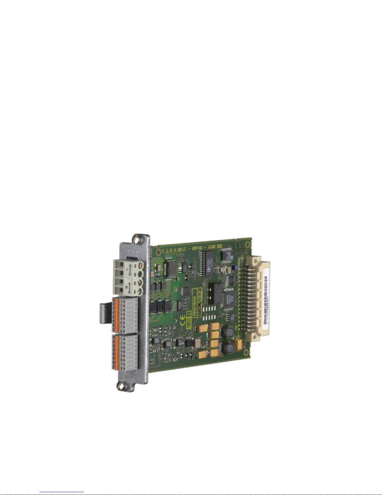
2
Description
The TB30 Terminal Board supports the addition of digital inputs/digital outputs and analog
inputs/analog outputs to the Control Unit.
The following are located on the TB30 Terminal Board:
● Power supply for digital inputs/digital outputs
● 4 digital inputs
● 4 digital outputs
● 2 analog inputs
● 2 analog outputs
The TB30 Terminal Board plugs into the option slot on the Control Unit.
A shield connection for the signal cable shield is located on the Control Unit.
Figure 2-1 Terminal Board TB30
Page 14

General
Terminal Board 30 (TB30)
14 Operating Instructions, 04/2014, A5E01221269A
Page 15

Terminal Board 30 (TB30)
Operating Instructions, 04/2014, A5E01221269A
15
3
NOTICE
Damage or malfunctions to the Option Board by inserting and withdrawing in operation
Withdrawing and inserting Option Boards during operation can damage them or cause the
Option Boards to malfunction.
• Only withdraw or insert Option Boards when the Control Unit is in a current-free state.
Figure 3-1 Installing an Option Board on a CU320-2 DP
Page 16

Mechanical installation
Terminal Board 30 (TB30)
16 Operating Instructions, 04/2014, A5E01221269A
Figure 3-2 Installing an Option Board on a CU320-2 PN
Page 17

Terminal Board 30 (TB30)
Operating Instructions, 04/2014, A5E01221269A
17
4
Interface overview
Figure 4-1 Interface description of the TB30
Page 18

Electrical installation
Terminal Board 30 (TB30)
18 Operating Instructions, 04/2014, A5E01221269A
Connection overview
Figure 4-2 Connection overview TB30
Page 19

Electrical installation
Terminal Board 30 (TB30)
Operating Instructions, 04/2014, A5E01221269A
19
X424 power supply, digital outputs
Table 4- 1 Terminal block X424
Terminal
Function
Technical specifications
+
Power supply
Voltage: 24 VDC (20.4 V – 28.8 V)
Current consumption: Max. 4 A (per digital output max. 0.5
A)
Max. current via jumper in connector:
20 A at 55° C
+
Power supply
M
Ground
M Ground
Max. connectable cross-section: 2.5 mm2
Note
The two "+" and "M" terminals are jumpered in the connector. This ensures that the supply
voltage is looped through.
This power supply is required for the digital outputs only.
The electronics power supply and the power supply for the analog inputs/output
s are taken
from the option slot of the Control Unit.
Note
The power supply of the digital outputs and the electronics power supply of the Control Unit
are optically isolated.
Note
If a the 24 V supply is briefly interrupted, then the digital outputs are deactivated during this
time.
Page 20

Electrical installation
Terminal Board 30 (TB30)
20 Operating Instructions, 04/2014, A5E01221269A
Digital inputs/outputs X481
Table 4- 2 Terminal strip X481
Terminal
Designation 1)
Technical specifications
1
DI 0
Voltage: - 3 … 30 V
Current consumption, typical: 10 mA at 24 VDC
Ground reference: X424.M
Input delay:
for "0" to "1": 20 μs
for "1" to "0": 100 μs
Level (incl. ripple)
High level: 15 … 30 V
Low signal level: -3 to 5 V
2
DI 1
3
DI 2
4 DI 3
5
DO 0
Voltage: 24 VDC
Max. load current per output: 500 mA
Ground reference: X424.M
Continuous short-circuit proof
Output delay:
for "0" to "1": typ. 150 μs at 0.5 A resistive load
(500 μs maximum)
for "1" to "0": Typically 50 μs at 0.5 A resistive load
Switching frequency:
for ohmic load: Max. 100 Hz
for inductive load: Max. 0.5 Hz
for lamp load: Max. 10 Hz
Maximum lamp load: 5 W
6
DO 1
7
DO 2
8 DO 3
Max. connectable cross-section: 0.5 mm2
1)
DI: digital input, DO: digital output
Note
An open input is interpreted as "low".
The power supply and the digital inputs/outputs are optically isolated from the Control Unit.
Note
If a the 24 V supply is briefly interrupted, then the digital outputs are deactivated during this
time.
Page 21

Electrical installation
Terminal Board 30 (TB30)
Operating Instructions, 04/2014, A5E01221269A
21
Analog inputs/outputs X482
Table 4- 3 Terminal strip X482
Terminal
Designation 1)
Technical specifications
1
AI 0+
Analog inputs (AI)
Voltage
: -10 … +10 V; Ri: 65 kΩ
Common-mode range
: ±30 V
Resolution
: 13 bits + sign
2
AI 0-
3
AI 1+
4
AI 1-
5
AO 0+
Analog outputs (AO)
Voltage range
: -10 to +10 V
Load current
: max. -3 … +3 mA
Resolution
: 11 bits + sign
Continuous short-circuit proof
6
AO 0-
7
AO 1+
8 AO 1-
Max. connectable cross-section: 0.5 mm2
1)
AI: Analog input, AO: Analog output
Note
Permissible voltage values
In order to avoid incorrect results of the analog
-digital conversion, the analog differential
voltage signals can have a maximum offset voltage of +/
-30 V with respect to ground
potential.
Note
An open input is interpreted as approximately "0 V".
The p
ower supply of the analog inputs/outputs is taken from the option slot of the Control
Unit and not from X424.
The shield is connected to the Control Unit.
Page 22

Electrical installation
Terminal Board 30 (TB30)
22 Operating Instructions, 04/2014, A5E01221269A
Shield connection of the TB30 on the Control Unit CU320
Figure 4-3 TB30 shield connection
The permissible bending radii for the cables must not be exceeded when the cables are
being installed.
Page 23

Terminal Board 30 (TB30)
Operating Instructions, 04/2014, A5E01221269A
23
5
General technical data
Table 5- 1 General technical data
Product standard
EN 61800-5-1
Technical data
Table 5- 2 Technical data
Unit
Value
Electronic power supply
Voltage
Current via the option slot of the CU
(without digital outputs)
Power loss
V
DC
A
DC
W
24 DC (20.4 – 28.8)
0.05
<3
Response time The reaction time of digital inputs/outputs and analog inputs/outputs depends on
the evaluation on the Control Unit (see function diagrams FP 9100 - FP 9106) in
the SINAMICS List Manual).
Weight
kg
0.1
Page 24

Technical specifications
Terminal Board 30 (TB30)
24 Operating Instructions, 04/2014, A5E01221269A
Page 25

Page 26

 Loading...