

Siemens TALON TXM1.16D, TALON TXM1.8X, TALON TXM1.6R, TALON TXM1.6R-M, TALON TXM1.8U-ML Technical Reference Manual
...Page 1

TALON TX-I/O Modules
and Island Bus Technical
Reference Manual
Siemens Industry, Inc.
588-587
Page 2

Technical specifications and availability subject to change without notice.
© 2010 Copyright Siemens Industry, Inc.
We reserve all rights in this document and in the subject thereof. By acceptance of the document the recipient acknowledges these rights and
undertakes not to publish the document nor the subject thereof in full or in part, nor to make them available to any third party without our prior
express written authorization, nor to use it for any purpose other than for which it was delivered to him.
Page 3

Copyright Notice
Notice
The information contained within this document is subject to change without notice by
Siemens Industry, Inc. Siemens Industry, Inc. assumes no responsibility for any errors
that may appear in this document.
All software described in this document is furnished under a license and may be used
or copied only in accordance with the terms of such license.
Warning
This equipment generates, uses, and can radiate radio frequency energy and if not
installed and used in accordance with the instructions manual, may cause interference
to radio communications. It has been tested and found to comply with the limits for a
Class A digital device, pursuant to Part 15 of the FCC rules. These limits are designed
to provide reasonable protection against such interference when operated in a
commercial environment. Operation of this equipment in a residential area is likely to
cause interference in which case users at their own expense will be required to take
whatever measures may be required to correct the interference.
Copyright Notice
Service Statement
Control devices are combined to make a system. Each control device is mechanical in
nature and all mechanical components must be regularly serviced to optimize their
operation. All Siemens Industry, Inc. branch offices and authorized distributors offer
Technical Support Programs that will ensure your continuous, trouble-free system
performance.
For further information, contact your nearest Siemens Industry, Inc. representative.
Copyright 2010 by Siemens Industry, Inc.
To the Reader
Your feedback is important to us. If you have comments about this manual, please
submit them to: SBT_technical.editor.us.sbt@siemens.com
Credits
TALON is a registered trademark of Siemens Industry, Inc.
Other product or company names mentioned herein may be the trademarks of their
respective owners.
Printed in USA
Siemens Industry, Inc. TALON TX-I/O Modules and Island Bus Technical Reference
588-587 CONFIDENTIAL: For internal use only 4/6/2010
3
Page 4

Copyright Notice
4
Siemens Industry, Inc. TALON TX-I/O Modules and Island Bus Technical Reference
588-587 CONFIDENTIAL: For internal use only 4/6/2010
Page 5

Table of contents
Copyright Notice ........................................................................................ 3
TX-I/O Product Range Overview ............................................................... 7
TX-I/O Modules ........................................................................................... 8
TX-I/O Module Feature Summary.............................................................................9
Local Override Feature.......................................................................................10
TX-I/O Module Specifications..................................................................................11
Consumption Data for I/O Points .......................................................................11
TX-I/O Module Assembly.........................................................................................13
Address Keys .....................................................................................................14
Separating a Module from its Terminal Base.....................................................15
TX-I/O Module Product Diagram.............................................................................16
Digital Input Modules (TXM1.8D and TXM1.16D)...................................................17
Digital Output Modules (TXM1.6R and TXM1.6R-M)..............................................18
Digital Output Common Connections.................................................................19
Universal I/O Modules (TXM1.8U and TXM1.8U-ML).............................................20
Supply Terminal Connections ............................................................................20
Digital Input Support...........................................................................................21
Active Input and Output Support........................................................................21
Local Override/Identification Device...................................................................22
Super Universal I/O Modules (TXM1.8X and TXM1.8X-ML)...................................24
Supply Terminal Connections ............................................................................25
Active Input and Output Support........................................................................25
Digital Input Support...........................................................................................27
Local Override/Identification Device...................................................................28
TX-I/O Power Supply and Bus Modules ................................................. 30
TX-I/O Power Supply Overview...............................................................................30
TX-I/O Power Supply Specifications..................................................................31
TX-I/O Power Supply Product Diagram .............................................................32
Bus Connection Module Overview..........................................................................33
TX-I/O Bus Connection Module Specifications..................................................33
Bus Connection Module Product Diagram.........................................................34
TX-I/O Island Bus...................................................................................... 35
Admissible Number of Devices ...............................................................................35
Structure of the Island Bus Rows............................................................................35
Installation Rules and Limitations.......................................................................35
Row Orientation..................................................................................................38
Installation and Commissioning...............................................................................40
Required Tools...................................................................................................40
Common Grounding Requirement.....................................................................41
Power Supply Wiring..........................................................................................43
Extending Communication .................................................................................44
Commissioning Notes ........................................................................................45
Siemens Industry, Inc. TALON TX-I/O Modules and Island Bus Technical Reference
588-587 CONFIDENTIAL: For internal use only 4/6/2010
5
Page 6

Replacing a TX-I/O Plug-in Module.........................................................................46
Replacing a TX-I/O Module Assembly.....................................................................47
Troubleshooting the TX-I/O Island Bus ..................................................48
6
Siemens Industry, Inc. TALON TX-I/O Modules and Island Bus Technical Reference
588-587 CONFIDENTIAL: For internal use only 4/6/2010
Page 7

TX-I/O Product Range Overview
CAUTION
This device includes electrical and electronic components and must not be
disposed of as domestic waste. Product recovery and disposal must comply with
all national and local regulations.
TX-I/O
™ is a line of I/O modules with associated power and communication modules
for use within the TALON system. The I/O modules reside on the TX-I/O
which simultaneously carries the supply voltages for the I/O modules and the field
devices and provides communication bus between the island bus controller and the
connected TX-I/O modules.
TX-I/O island bus communication requires one of the following controllers:
TC Modular
TC-36
TX-I/O Product Range Overview
island bus
,
TC Modular
The TC Modular connects to the island bus through a TX-I/O Power Supply or TX-
I/O Bus Connection Module using standard DIN rails.
The TC Modular provides the control database and communications for points on
TX-I/O modules, but it does not supply power.
TC-36
The TC-36 connects to the island bus through a TX-I/O Power Supply or TX-I/O
Bus Connection Module using island bus connectors.
The TC-36 provides the control database and communications for points on TX-I/O
modules, but it does not supply power.
Siemens Industry, Inc. TALON TX-I/O Modules and Island Bus Technical Reference
588-587 CONFIDENTIAL: For internal use only 4/6/2010
7
Page 8

TX-I/O Modules
TX-I/O Modules
TX-I/O Modules are modular expansion I/O consisting of an electronics module and a
terminal base; they receive power from a TX-I/O Power Supply or Bus Connection
Module.
The electronics module performs A/D or D/A conversion, signal processing, point
monitoring, and command output.
The terminal base provides for termination of field wiring and connection of the self-
forming TX-I/O island bus.
The design of the TX-I/O Modules provides optimum diagnostics and results in a more
efficient installation and maintenance workflow.
Field wiring may be terminated prior to installation of electronics.
Connected peripheral devices can be measured without affecting or being affected
by the I/O module.
Hot-swappable electronic components
allow powered electronics to be
disconnected and replaced without removing terminal wiring or disturbing the selfforming bus.
8
Siemens Industry, Inc. TALON TX-I/O Modules and Island Bus Technical Reference
588-587 CONFIDENTIAL: For internal use only 4/6/2010
Page 9

TX-I/O Module Feature Summary
CAUTION
Active inputs and output are permitted on the same module when connected
TXM1.
Function 8 Super
Local Override • • • General
LCD Display • •
AI
DI
1)
4-20 mA functionality is available only point terminations 5-8
2)
10 Hz counter functionality is available only on point terminations 1-8
NI 1000 LS • • • •
PT 1000 385 • • • •
LT 1000 375 • • • •
NTC 10K (w/out diode) • • • •
NTC 100K • • • •
0-10 Vdc • • • •
4-20 mA • •
0-10 Vdc • • • • AO
4-20 mA •1 •
Static Contact (NC/NO) • • • • • •
Pulse accumulator • • • • • •
25 Hz Counter (with debouncing) • • • •
10 Hz Counter (with debouncing) •
ON/OFF • • DO
Pulse ON • •
sensors are powered from that module.
When sensors are externally powered, active inputs and outputs should be on
separate modules.
TX-I/O Module Product Number and Name
8X-ML
Universal
TX-I/O Modules
TXM1.
8X
TXM1.
8U-ML
TXM1.
8U
TXM1.
8D
TXM1.
16D
TXM1.
6R-M
TXM1.
6R
8 Universal 8 DI 16 DI 6 DO Relay
1
2
•
Siemens Industry, Inc. TALON TX-I/O Modules and Island Bus Technical Reference
588-587 CONFIDENTIAL: For internal use only 4/6/2010
9
Page 10

TX-I/O Modules
Local Override Feature
Do not use the local override for safety shutdown operations, such as performing
service or maintenance. Use suitable emergency switches instead.
The local override feature is only available on certain I/O modules.
In principle, plug-in I/O modules with and without a local LCD panel/operator
Only outputs can be overwritten. Any attempt to overwrite an input results in an
Local override also operates without a bus master, provided that the 24 Vdc
With a change from automatic mode to local override, the last state is retained The
The TC Modular or TC-36 is notified of local overrides and the associated values,
WARNING
controls are compatible and interchangeable.
error.
module supply is present and the address key is plugged in.
TC Modular or TC-36 resumes control when the system is switched back to Auto.
and they are permanently saved in the module.
Override Button
Pressing an override button in the middle enables or disables the local override (press
until the override status LED changes to ON or OFF).
When local override is enabled:
Pressing "+" increases an output value or activates the relay.
Pressing "–" reduces an output value or disables the relay.
Repeated or sustained pressure changes the value by several stages until the
function stops at the highest/lowest stage.
The I/O status LED and LCD display change accordingly.
Pressing "+" or "–" when local override is disabled results in an error.
10
Siemens Industry, Inc. TALON TX-I/O Modules and Island Bus Technical Reference
588-587 CONFIDENTIAL: For internal use only 4/6/2010
Page 11

TX-I/O Module Specifications
TX-I/O Modules
Dimensions (L × W × D) 2.52” × 3.54” × 2.75”
Power Requirements 24 Vac +/-20% input @ 50 or 60 Hz
Ambient operating temperature 32°F to +122°F (0°C to 50°C), 5 to 93% rh, non-condensing
UL UL 864 UUKL Smoke Control Equipment
UL 864 UUKL7 Smoke Control Equipment
Agency Compliance CFR47 Part 15, Class A; CFR47 Part 15, Class B
Australian EMC Framework (C-Tick)
2004/108/EC European EMC Directive (CE)
2006/95/EC European Low Voltage Directive (LVD)
(64 mm × 90 mm × 70 mm)
UL 916 PAZX
CSA 22.2 No. 205 PAZX7
Power Data by Module Type
Product Number Power Consumption 24 Vdc Output Bus
Voltage
TXM1.8D 1.1 W - TXM1.16D 1.4 W - TXM1.8U 1.5 W - 96 VA
TXM1.8U-ML 1.8 W - 96 VA
TXM1.8X 2.2 W 4.8 W max
(~200 mA).
TXM1.8X-ML 2.3 W 4.8 W max
(~200 mA).
TXM1.6R 1.7 W - TXM1.6R-M 1.9 W - -
24 Vac Supply
Voltage
96 VA
96 VA
Consumption Data for I/O Points
Consumption data for the following devices is required as an aid to transformer and
TX-I/O Power Supply sizing and to estimate the heat emitted in the enclosure:
Transformers (intrinsic consumption)
TC Modular or TC-36
Other field panel controllers
Power supply modules (intrinsic consumption)
All individual I/O points
Field devices (connected to the module supply or to separate transformers)
Siemens Industry, Inc. TALON TX-I/O Modules and Island Bus Technical Reference
588-587 CONFIDENTIAL: For internal use only 4/6/2010
11
Page 12

TX-I/O Modules
NOTE:
The 24 Vdc consumption from the modules of field devices other than current
sensors must be counted separately. Admissible current for each TXM1.8X or
TXM1.8X-ML module: 200 mA.
TX-I/O Module Consumption Data
(24 Vdc per I/O point, values in mA for supply sizing)
TXM1.
8X-ML
Function 8 Super
Intrinsic consumption 1) 35 30 60 35 25 25 30 20 General
Unconfigured I/O point
(Reserve for later configuration)
AI
Temperature sensors Ni, PT 3) 0 0 0 0
Temperature sensor NTC 3) 0 0 0 0
Resistance 3) 0.5 0.5 1 1
10 Vdc 2) 0.5 0.5 1 1
20 mA, Supply external or 24 Vac 2) 0.5 0.5
20 mA, 2-wire 2) 20 20
20 mA, 3-wire
2) 4)
25 25
10 Vdc 2) 2.5 2.5 3 3 AO
2)
20 mA
18 18
DI Contact closed 2) 2 2 3 3 3.5 2.5
DO Relay, contact closed 2) 8 8
1)
Including module status LED; includes LCD and all override LEDs if applicable.
2)
Including I/O status LED.
3)
Included in intrinsic consumption (no I/O status LED for temperature inputs).
4)
The table assumes 5 mA to supply the current sensor, which should be sufficient for most models. If in doubt, please refer to the
sensor data sheet.
TXM1.
8X
TXM1.
8U-ML
TXM1.
8U
TXM1.
8D
TXM1.
16D
TXM1.
6R-M
TXM1.
6R
8 Universal 8 DI 16 DI 6 DO Relay
Universal
25 25 3 3 3.5 2.5 8 8
12
Siemens Industry, Inc. TALON TX-I/O Modules and Island Bus Technical Reference
588-587 CONFIDENTIAL: For internal use only 4/6/2010
Page 13

TX-I/O Module Assembly
The following figure shows the general TX-I/O Module components and hardware
features.
TX-I/O Modules
7
6
17
8
18
9
10
11
12
13
TXIO0028R1
5
4
3
16
2
14
15
1
I/O Module Assembly.
1 Standard DIN mounting rail (not included) 10 Electrical contact between terminal base and
plug-in module
2 Terminal base (plug-in base for the I/O
module)
3 Plug-in module (the functioning component of
the I/O module assembly)
4 Local override facility (not applicable to all
types)
5 LCD display (not applicable to all types) 14 TX-I/O bus connector
6 Detachable label holder 15 TX-I/O bus connector cover
7 Module label (not included) 16 Module lock
8 Address key with mechanically encoded
module address
9 Plug-in contacts between the terminal base
and the plug-in module
Siemens Industry, Inc. TALON TX-I/O Modules and Island Bus Technical Reference
588-587 CONFIDENTIAL: For internal use only 4/6/2010
11 Terminal screws
12 Test pickups (test points)
13 Slide fitting to lock assembly into position on
standard mounting rail
17 Module disengage catch
18 Module release catch
13
Page 14

TX-I/O Modules
Address Keys
I/O modules are addressed using a TX-I/O address key.
Reset Key
TXIO0062R1
TX-I/O Address Keys.
The keys are available in sets of 24, up to a maximum value of 72 (2 sets of 12, 1-24,
25-48, and 49-72).
The I/O module address is mechanically encoded in the address key.
‒ Without an address key, the module is inactive.
‒ With an address key inserted, the module has full functionality.
Based on the address, the TC Modular or TC-36 configures the I/O module,
indicates which field devices are connected to this module, and which function is
required for the field devices.
CAUTION
The address key must be inserted firmly into the terminal base before swiveling it
into the plug-in module.
1
TXIO0039R1
14
Siemens Industry, Inc. TALON TX-I/O Modules and Island Bus Technical Reference
588-587 CONFIDENTIAL: For internal use only 4/6/2010
TXIO0040R1
2
Page 15

Swiveling the Address Key Out
TXIO0056R1
To remove,
squeeze sides of
module and pull
"Parked" position Normal position
When the address key is swiveled out, the I/O module is inactive, and it cannot be
overridden locally. The state (automatic operation, tool override, or local override),
configuration, and parameters of the individual I/O points are saved in the non-volatile
memory of the plug-in module.
Swiveling the Address Key Back into Place
When a fault is repaired or an address key is swiveled back into place, operation
resumes in the same state as before (automatic operation, tool override, or local
override). The process values are only stored in tool override or local override.
Separating a Module from its Terminal Base
TX-I/O Modules
Separating a Module from its Terminal Base.
To Park a Module
In the "parked" position the plug-in modules are fully isolated from the terminal bases.
The connected field devices can be measured through the test pickups without being
affected by the plug-in module electronics.
1. Squeeze module sides above the disengage catch and pull up slightly to disengage
the I/O module from the terminal base.
2. The I/O module is retained in the terminal base (‘parked’), but all wiring
connections are now floating.
To Remove a Module
Squeeze module sides above the release catch and pull up to remove the I/O module
from the terminal base.
Siemens Industry, Inc. TALON TX-I/O Modules and Island Bus Technical Reference
588-587 CONFIDENTIAL: For internal use only 4/6/2010
15
Page 16

TX-I/O Modules
TX-I/O Module Product Diagram
3
20 24 28 32
VVVV
19 21 23 25 27 29 31 33
(5) (6) (7) (8)
1
TXM1.8X-ML
(1) (2) (3) (4) (5) (6) (7) (8)
2
(1)
2
TXIO0055R1
(2)
(3)
(4)
4
68
10 12
14
VVVV
3
71511
TX-I/O Module Symbols and Status LEDs
LED, Symbol, or Feature LED or Symbol Indication
1 Address key and module status
LED (green)
Flashing or pulsing - Fault indication
2 I/O point numbers - 3 Terminal number - 4 Test terminal -
5 Connection terminals -
6
- Module status as a whole (as opposed to the I/O points).
ON Normal operation. 24 Vac (supply voltage) input present;
fuse is intact.
OFF Error.
- No 24 Vac (supply voltage) input.
- Fuse is blown.
- No address key
- Remote override
- System neutral.
- Configurable point.
- Output (arrow pointing OUT from center of module).
- Input (arrow pointing IN toward center module).
- 24 Vdc output (field supply).
- 24 Vac output (field supply).
4
5
6
7
8
+
9
10
16
16
Siemens Industry, Inc. TALON TX-I/O Modules and Island Bus Technical Reference
588-587 CONFIDENTIAL: For internal use only 4/6/2010
Page 17

TX-I/O Module Symbols and Status LEDs
7 Override status LEDs (yellow)
ON Manual operation; a local override is active.
OFF No voltage or manual operation off.
Flashing or pulsing - Override action
- Remote override
- Output: Local override is off, operation is not possible.
- Input: Operation is not possible.
8 LCD signal display - Only on a TX-I/O modules with –ML suffix.
9 Local override switch - Only on a TX-I/O with –M or –ML suffix.
10 I/O status LEDs (green)
- Status of the inputs and outputs (peripheral devices). LEDs
are labeled with the I/O point number.
ON Binary value indication.
OFF No voltage or binary value indication.
Flashing or pulsing - Fault indication
- Activity of field devices
- Module unconfigured, no address key
- Analog value indication
TX-I/O Modules
Digital Input Modules (TXM1.8D and TXM1.16D)
18
TXM1.8D
(1)
(2) (3) (4) (5) (6) (7) (8)
(1)
(2)6(3)8(4)10(5)12(6)14(7)16(8)
2
4
31 5 7 9 11 13 15
TXIO0022R1
The TXM1.8D and TXM1.16D are dedicated to monitoring, respectively, 8 and 16
digital input points.
They monitor status signals from normally open (NO) or normally closed (NC),
latched voltage free/dry contacts.
TXIO0020R1
20 22 24 26 28 30 32
19 21 23 25 27 29 31 33
(9) (10) (12)(11) (13) (14) (15) (16)
TXM1.16D
(2)
(4) (6) (8) (10) (12) (14) (16)
(1)
(2)6(3)8(4)10(5)12(6)14(7)
2
4
31 5 7 9 11 13 15
(8)
16
All 8 points on the TXM1.8D module as well as 8 of the 16 points on the TXM1.16D
module may be used as pulse counters up to 10 Hz.
Each input point has a green LED for status indication.
NOTE:
Siemens Industry, Inc. TALON TX-I/O Modules and Island Bus Technical Reference
588-587 CONFIDENTIAL: For internal use only 4/6/2010
Potential free (dry contact) for all points.
17
Page 18

TX-I/O Modules
Digital Input Grounding Connections
The neutral of a digital input (on Digital Input, Universal and Super Universal modules)
can be connected to any neutral terminal on the same module. Several digital inputs
can also share a neutral terminal on the same module.
Technical Data
Digital inputs are not electrically separated from the system electronics.
Mechanical contacts must be volt-free.
Contact sensing voltage 21.5 to 25 Vdc
Contact sensing current 1.6 mA (initial current 10 mA)
Contact resistance with contacts closed Max. 200Ω
Insulation resistance with contacts open Max. 50KΩ
Min. closing / opening
time [ms] including
bouncing
Maintained contact 80 40
Pulse contact 50 30
Counter1) 40 30 10 Hz
1)
Counting function for TXM1.16D is on I/O points 1 through 8 only.
Max. bounce time
[ms]
Max. Counting
frequency
(symmetric)
Digital Output Modules (TXM1.6R and TXM1.6R-M)
20 26 32
19 21 25 27 31 33
(4) (5) (6)
24V ...250V
(1) (2) (3) (4) (5) (6)
(1)
2
4
3915
TXIO0018R1
(2)
810
TXM1.6R
(3)
14
16
The TXM1.6R and TXM1.6R-M Digital Output modules provide six NO or NC (form C),
maintained or pulsed, voltage free/dry contacts.
20 26 32
19 21 25 27 31 33
(4) (5) (6)
24V ...250V
(1)
2
3 9 15
TXIO0021R1
TXM1.6R-M
(1) (2) (3) (4) (5) (6)
(2)
4
8 10
+
(3)
14
16
18
Siemens Industry, Inc. TALON TX-I/O Modules and Island Bus Technical Reference
588-587 CONFIDENTIAL: For internal use only 4/6/2010
Page 19

TX-I/O Modules
CAUTION
Digital Output contacts are not internally current-limited or protected against
transients. If needed, externally install an NEC-approved current limiting device,
Metal Oxide Varistor (MOV), or both. See the MOV table in the
Guidelines Manual
Common terminals are not internally connected.
The contacts are rated for a maximum of 250 Vac at 4A resistive or 3A inductive.
Each I/O point has a green LED for status indication.
The TXM1.6R-M module is also equipped with manual override switches. An
(588-581).
orange LED per override switch indicates override status individually per point.
Digital Output Common Connections
Digital Output common is isolated for each relay and must be externally wired to other
DO common if needed.
DANGER
Digital Output modules connected to high voltage should incorporate a readily
accessible disconnect device outside the panel. All low voltage and high voltage
wiring must be routed separately within an enclosure so that low voltage and high
voltage wiring cannot come in contact with each other. High- and low-voltage
TALON Wiring
circuits cannot be located on adjacent terminals within a module.
DANGER
Separate knockouts should be used for high voltage and low voltage wiring.
Leave at least 2 inches (50.8 mm) of space between the Class 2 wires and other
wires in the panel.
19
Siemens Industry, Inc. TALON TX-I/O Modules and Island Bus Technical Reference
588-587 CONFIDENTIAL: For internal use only 4/6/2010
Page 20

TX-I/O Modules
Universal I/O Modules (TXM1.8U and TXM1.8U-ML)
The TXM1.8U and TXM1.8U-ML universal I/O modules provide 8 points, which can be
individually software configured as digital input, analog input, or analog output to best
meet the specific application needs.
24 32
VV
19 21 25 2723 29 31 33
(5) (6) (7) (8)
TXM1.8U
19 21 25 2723 29 31 33
(1) (2) (3) (4) (5) (6) (7) (8)
24 32
VV
(5) (6) (7) (8)
TXM1.8U-ML
+
(1) (2) (3) (4) (5) (6) (7) (8)
(1)
(2)
(3)
2
TXIO0047R1
(4)
468
10 12
14
VV
7
15
16
(1)
2
TXIO0023R1
(2)
(3)
(4)
468
10 12
14
VV
7
15
16
All Universal I/O modules provide:
AC supply voltage for peripheral devices, such as valves and actuators.
Green LED status per I/O point that varies in intensity according to the voltage and
current (directly proportional).
Supply Terminal Connections
NOTE:
20
Siemens Industry, Inc. TALON TX-I/O Modules and Island Bus Technical Reference
588-587 CONFIDENTIAL: For internal use only 4/6/2010
The neutral of analog inputs and outputs must always be connected to the
terminal associated with that I/O input.
All supply terminals are connected in the I/O module, not in the terminal base.
The neutral of a digital input (on Digital Input, Universal and Super Universal
modules) can be connected to any neutral terminal on the same module. Several
digital inputs can also share a neutral terminal on the same module.
AC/DC Output (Field Supply)
The following information applies to terminals 7, 15, 24, and 32.
Voltage AC/DC 12 to 24 V
Admissable current per module Max. 4 A (total for all four terminals)
Fuse 4A, in TX-I/O Power Supply or
Bus Connection Module
Page 21

Digital Input Support
TX-I/O Modules
NOTE:
Potential free (dry contact) for all points.
Digital input support includes:
Voltage free/dry contacts.
Pulse counters up to 25 Hz.
Digital Input Grounding Connections
The neutral of a digital input (on Digital Input, Universal and Super Universal modules)
can be connected to any neutral terminal on the same module. Several digital inputs
can also share a neutral terminal on the same module.
Technical Data
Digital inputs are not electrically separated from the system electronics.
Mechanical contacts must be volt-free.
Counter inputs faster than 1 Hz that are routed for more than 32.8 ft (10 m) in the
same trunking as analog inputs must be shielded.
Contact sensing voltage 21.5 to 25 Vdc
Contact sensing current 1.0 mA (initial current 6 mA)
Contact resistance with contacts closed Max. 200Ω
Insulation resistance with contacts open Max. 50KΩ
Min. closing / opening
Maintained contact 60 20
Pulse contact 30 10
Mechanical Counter 20 10 25 Hz
Active Input and Output Support
CAUTION
Active inputs and outputs are permitted on the same module when connected
sensors are powered from that module. When sensors are externally powered,
time [ms] including
bouncing
Max. bounce time
[ms]
Max. Counting
frequency
(symmetric)
active inputs and outputs should be on separate modules.
NOTE:
The neutral of analog inputs and outputs must always be connected to the
terminal associated with that I/O input.
Active input and output support includes analog input and output (0-10 Vdc).
21
Siemens Industry, Inc. TALON TX-I/O Modules and Island Bus Technical Reference
588-587 CONFIDENTIAL: For internal use only 4/6/2010
Page 22

TX-I/O Modules
Analog Input Sensor Support
Analog input sensor support includes:
1K Nickel – Landis & Gyr curve
1K Platinum – 375 and 385 coefficient
10K and 100K Thermistor – Type II Curve
Technical Data for Analog Inputs on TX-I/O Modules TXM1.8U,
TXM1.8U-ML, TXM1.8X, and TXM1.8X-ML
Compensation of the line
resistance
Signal type Range Resolution 2) Sensor current
Temperature Pt1K 375 -50…150 (180) °C 1) 10 mK 1.54 mA
Temperature Pt1K 385 -50...400 (600) °C 1) 20 mK 1.96 mA
Temperature Ni1K (LG-Ni 1000) -50…150 (180) °C 1) 10 mK 1.54 mA
Temperature NTC 10K (-40 ...115 °C) 1) 10 mK (25°C) 0.14 mA
Temperature NTC 100K (-40 ...125 °C) 1) 10 mK (25°C) 0.14 mA
Voltage measuring U10 0 ... 10 V 3) 1 mV
Current measuring I420 4 ... 20 mA 1 mA
Load resistance 490 / 440 Ohm,
1)
(extended range) only with reduced hum injection (see below)
2)
This section describes the measured resolution. It is different from the transmitted resolution that the bus delivers into the AI block
and that is transformed by [Slpe] and [Icpt]
3)
The range monitoring of signal type U10 is done with a short NEGATIVE signal of –3,1 V, 0.05 mA (open circuit detection). If a field
device has an open output, a negative voltage could appear there. This can damage any polarized components (e.g. capacitors).
1 Ohm, calibrated in the module, (except for NTC10K and NTC100K)
(cyclic polling)
pulsed (cyclic polling
of the I/O points)
Local Override/Identification Device
TXM1.8U-ML and TXM1.8X-ML modules are also equipped with a local
override/identification device (LOID), which includes an LCD signal display. The LCD
displays the following information for each IO point:
Configured signal type
Symbolic display of process value
Notification of faulty operation, short circuit, or sensor open circuit
Orange LEDs indicate override status individually per point.
22
Siemens Industry, Inc. TALON TX-I/O Modules and Island Bus Technical Reference
588-587 CONFIDENTIAL: For internal use only 4/6/2010
Page 23

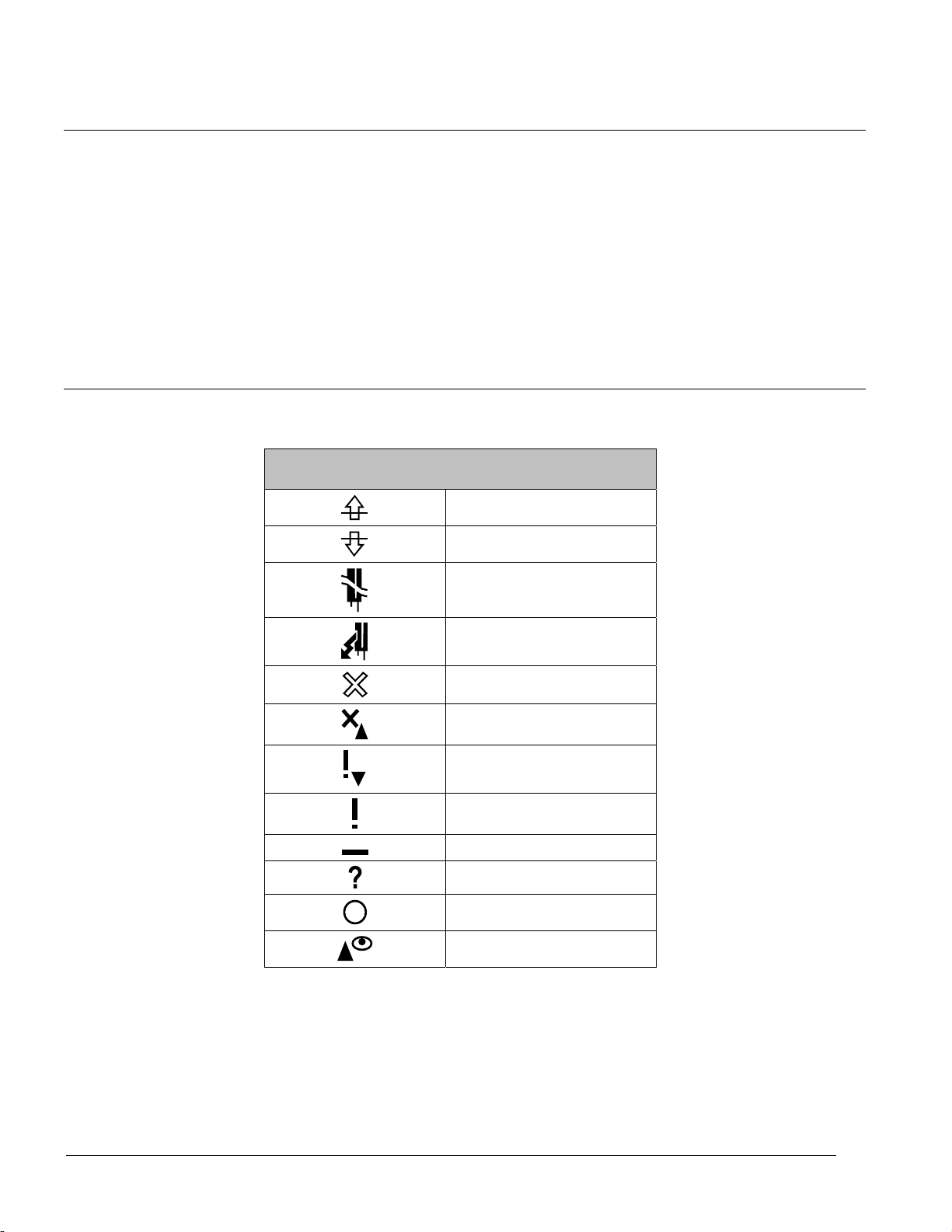
TX-I/O Module LCD Symbol Chart
The TX-I/O module LCD displays a symbol to indicate each point type and its current
value.
TX-I/O Module LCD Display for Errors and Reminders
(Displays in LCD Top Row)
Point Type
(Displays in LCD Bottom Row)
Analog Input, Current
Analog Input, Resistance
Analog Input, Voltage
Analog Output, Current
Analog Output, Voltage
Digital Input, Counter
Value above range limit
Value below range limit
Open circuit
Short circuit
Point in manual override
No sensor (current)
No output signal
24 Vdc supply < 22 Vdc
Inactive point
Invalid value
No voltage
Unconfigured point
TX-I/O LCD Display by Point Type.
Normal Operation
(Displays in LCD Top Row)
TX-I/O Modules
Low or high value
Temperature
Low or high value
Low or high value
Low or high value
Step indicator
23
Siemens Industry, Inc. TALON TX-I/O Modules and Island Bus Technical Reference
588-587 CONFIDENTIAL: For internal use only 4/6/2010
Page 24

TX-I/O Modules
Point Type
(Displays in LCD Bottom Row)
Digital Input, N/C Contact
TX-I/O LCD Display by Point Type.
Normal Operation
(Displays in LCD Top Row)
Inactive
Active
Digital Input, N/O Contact
Inactive
Super Universal I/O Modules (TXM1.8X and TXM1.8X-ML)
The TXM1.8X and TXM1.8X-ML Super Universal I/O modules provide 8 points, which
can be individually configured as analog output, analog input, or digital input to best
meet the specific application needs.
20 24 28 32
VVVV
19 21 23 25 27 29 31 33
(5) (7)(6) (8)
(1) (2) (3) (4) (5) (6) (7) (8)
(1)
2
(6)
TXM1.8X
(2)
(3)
(4)
4
6 8
10 12
14
16
20 24 28 32
VVVV
19 21 23 25 27 29 31 33
(5) (6) (7) (8)
(1) (2) (3) (4) (5) (6) (7) (8)
(1)
(2)
(3)
2
4
68
10 12
Active
TXM1.8X-ML
(4)
14
+
16
VVVV
3 7 1511
TXIO0024R1
VVVV
3
71511
TXIO0025R1
NOTE:
All supply terminals are connected in the I/O module, not in the terminal base.
All Super Universal I/O modules provide:
AC supply voltage for peripheral devices such as valves and actuators
Green LED status per I/O point that varies in intensity according to the voltage and
current (directly proportional)
24
Siemens Industry, Inc. TALON TX-I/O Modules and Island Bus Technical Reference
588-587 CONFIDENTIAL: For internal use only 4/6/2010
Page 25

Supply Terminal Connections
NOTE:
The neutral of analog inputs and outputs must always be connected to the
terminal associated with that I/O input.
All supply terminals are connected in the I/O module, not in the terminal base.
The neutral of a digital input (on Digital Input, Universal and Super Universal
modules) can be connected to any neutral terminal on the same module. Several
digital inputs can also share a neutral terminal on the same module.
DC Output (Field Supply)
The following information applies to terminals 3, 11, 20, and 28.
TX-I/O Modules
Nominal voltage (derived in the module from
the module supply voltage)
Admissable current per module Max. 200 mA (total for all four terminals)
AC/DC Output (Field Supply)
The following information applies to terminals 7, 15, 24, and 32.
Voltage AC/DC 12 to 24 V
Admissable current per module Max. 4 A (total for all four terminals)
Fuse 4A, in TX-I/O Power Supply or
Active Input and Output Support
CAUTION
Active inputs and output are permitted on the same module when connected
sensors are powered from that module.
When sensors are externally powered, active inputs and outputs should be on
separate modules.
24 Vdc
Bus Connection Module
NOTE:
The neutral of analog inputs and outputs must always be connected to the
terminal associated with that I/O input.
Active input and output support includes the following:
Analog input and output (0-10 Vdc)
Analog input current 4-20 mA
Analog output current 4-20 mA (four current outputs maximum per module on
Points 5 through 8)
24 Vdc supply voltage for sensors at a maximum of 200 mA per module.
25
Siemens Industry, Inc. TALON TX-I/O Modules and Island Bus Technical Reference
588-587 CONFIDENTIAL: For internal use only 4/6/2010
Page 26

TX-I/O Modules
Compensation of the line
resistance
NOTE:
4 to 20 mA current handling capability is available on points 1 through 4 (AIs only)
and points 5 through 8 (AIs or AOs).
Power consumption of analog points is included in the power consumption of the
8X module. Power consumption of other approved uses of supply voltage (for
example, 1000 series RTS supply) must also be subtracted from the available 24
Vdc power provided by the TX-I/O Power Supply.
Analog Input Support
Analog input sensor support includes:
1K Nickel – Landis & Gyr curve
1K Platinum – 375 and 385 coefficient
10K and 100K Thermistor – Type II Curve
Technical Data for Analog Inputs on TX-I/O Modules TXM1.8U,
TXM1.8U-ML, TXM1.8X, and TXM1.8X-ML
1 Ohm, calibrated in the module, (except for NTC10K and NTC100K)
Signal type Range Resolution 2) Sensor current
(cyclic polling)
Temperature Pt1K 375 -50…150 (180) °C 1) 10 mK 1.54 mA
Temperature Pt1K 385 -50...400 (600) °C 1) 20 mK 1.96 mA
Temperature Ni1K (LG-Ni 1000) -50…150 (180) °C 1) 10 mK 1.54 mA
Temperature NTC 10K (-40 ...115 °C) 1) 10 mK (25°C) 0.14 mA
Temperature NTC 100K (-40 ...125 °C) 1) 10 mK (25°C) 0.14 mA
Voltage measuring U10 0 ... 10 V 3) 1 mV
Current measuring I420 4 ... 20 mA 1 mA
Load resistance 490 / 440 Ohm,
1)
(extended range) only with reduced hum injection (see below)
2)
This section describes the measured resolution. It is different from the transmitted resolution that the bus delivers into the AI block
and that is transformed by [Slpe] and [Icpt]
3)
The range monitoring of signal type U10 is done with a short NEGATIVE signal of –3,1 V, 0.05 mA (open circuit detection). If a field
device has an open output, a negative voltage could appear there. This can damage any polarized components (e.g. capacitors).
pulsed (cyclic polling
of the I/O points)
26
Siemens Industry, Inc. TALON TX-I/O Modules and Island Bus Technical Reference
588-587 CONFIDENTIAL: For internal use only 4/6/2010
Page 27

Digital Input Support
TX-I/O Modules
Technical Data for Analog Outputs on TX-I/O Modules TXM1.8X and
TXM1.8X-ML
Signal type Range Resolution
Voltage Y10S 0 љ10 V 1 mV
Current Max. 1 mA
Current Y420
(I/O points 5 through 8 only)
Voltage ca. DC 15 V
Load resistance 0 ... 500 Ω
Digital input support includes voltage free/dry contacts and pulse counters up to 20 Hz.
NOTE:
Potential free (dry contact) for all points.
The neutral of a digital input can be connected to any neutral terminal on the
4 ... 20 mA 1 μA
same module. Several digital inputs can also share a neutral terminal on the
same module.
Technical Data
Digital inputs are not electrically separated from the system electronics.
Mechanical contacts must be volt-free.
Counter inputs faster than 1 Hz that are routed for more than 32.8 ft (10 m) in the
same trunking as analog inputs must be shielded.
Contact sensing voltage 21.5 to 25 Vdc
Contact sensing current 1.0 mA (initial current 6 mA)
Contact resistance with contacts closed Max. 200Ω
Insulation resistance with contacts open Max. 50KΩ
Min. closing / opening
time [ms] including
bouncing
Maintained contact 60 20
Pulse contact 30 10
Mechanical Counter 20 10 25 Hz
Max. bounce time
[ms]
Max. Counting
frequency
(symmetric)
27
Siemens Industry, Inc. TALON TX-I/O Modules and Island Bus Technical Reference
588-587 CONFIDENTIAL: For internal use only 4/6/2010
Page 28
TX-I/O Modules
Local Override/Identification Device
TXM1.8U-ML and TXM1.8X-ML modules are also equipped with a local
override/identification device (LOID), which includes an LCD signal display. The LCD
displays the following information for each IO point:
Configured signal type
Symbolic display of process value
Notification of faulty operation, short circuit, or sensor open circuit
Orange LEDs indicate override status individually per point.
TX-I/O Module LCD Symbol Chart
The TX-I/O module LCD displays a symbol to indicate each point type and its current
value.
TX-I/O Module LCD Display for Errors and Reminders
(Displays in LCD Top Row)
Value above range limit
Value below range limit
Open circuit
Short circuit
Point in manual override
No sensor (current)
No output signal
24 Vdc supply < 22 Vdc
Inactive point
Invalid value
No voltage
Unconfigured point
28
Siemens Industry, Inc. TALON TX-I/O Modules and Island Bus Technical Reference
588-587 CONFIDENTIAL: For internal use only 4/6/2010
Page 29

Point Type
(Displays in LCD Bottom Row)
Analog Input, Current
Analog Input, Resistance
Analog Input, Voltage
Analog Output, Current
Analog Output, Voltage
Digital Input, Counter
Digital Input, N/C Contact
TX-I/O LCD Display by Point Type.
Normal Operation
(Displays in LCD Top Row)
Inactive
TX-I/O Modules
Low or high value
Temperature
Low or high value
Low or high value
Low or high value
Step indicator
Active
Digital Input, N/O Contact
Inactive
Active
29
Siemens Industry, Inc. TALON TX-I/O Modules and Island Bus Technical Reference
588-587 CONFIDENTIAL: For internal use only 4/6/2010
Page 30

TX-I/O Power Supply and Bus Modules
TX-I/O Power Supply and Bus Modules
The TX-I/O Power Supply and Bus Connection Module provide power and
communications for the TX-I/O modules.
Function
Product TX-I/O Bus
TX-I/O Power Supply
(TXS1.12F4)
Bus Connection Module
(TXS1.EF4)
1)
May be used for Smoke Control installations with Smoke Control Listed Enclosures and
1
1
transformers or service boxes. The line to the 24 Vac input transformer must not exceed 1000 VA.
NEC Class 2 wiring may be used up to 96 VA, and NEC Class 1 Power Limited wiring must be
used above 96 VA and up to 1000 VA.
Communication
Signal pass-thru 28.8W at 1.2 A - Output fused at 4A
Signal pass-thru Pass-thru - Output fused at 4A
24 Vdc power 24 Vac power
- NEC Class 2
96 VA max. (Output)
- Class 1 Power Limited
150 VA max. (Input)
- NEC Class 2
96 VA max. (Output and
Input)
TX-I/O Power Supply Overview
The TX-I/O Power Supply bridges communication and power from one DIN rail to
another and generates 28.8 W (1.2A at 24 Vdc) to power TX-I/O modules and
peripheral devices.
An LED provides an indication of 24 Vdc on the TX-I/O bus.
Up to 4 TX-I/O Power Supplies can be operated in parallel, with a maximum of two
per DIN rail.
It can be located within a row of TX-I/O modules or at the beginning of a new DIN
rail.
The TX-I/O Power Supply performs the following functions:
Transfers 24 Vac at 4A to power TX-I/O modules and peripheral devices.
Provides an input point for 24 Vac to power additional peripheral devices.
‒ Isolates the 24 Vac peripheral device supply in case of overload or short-circuit.
‒ The replaceable AC fuse can be accessed from an installed module.
‒ Indicates the AC fuse status with an LED for easy diagnostics.
Routes the bus signal between DIN rails (+24 Vdc Communication Supply (CS)
and Communication Data (CD) signals).
30
Siemens Industry, Inc. TALON TX-I/O Modules and Island Bus Technical Reference
588-587 CONFIDENTIAL: For internal use only 4/6/2010
Page 31

TX-I/O Power Supply and Bus Modules
Supply Terminal Connections
24 Vac supply terminals are fused (replaceable) for Class 2 (24 Vac at 50/60 Hz)
through the TX-I/O Power Supply.
24 Vdc supply terminals are connected in the I/O module, not in the terminal base.
24 Vdc is supplied and overload protected in the TX-I/O Power Supply.
TX-I/O Power Supply Specifications
Dimensions (L × W × D) 3.78” × 3.54” × 2.75”
(96 mm × 90 mm × 70 mm)
TX-I/O Bus Communication Signal pass-thru
Power Requirements 24 Vac +/-20% input @ 50 or 60 Hz
Power Consumption
(Maximum)
Power Output 28.8 W (1.2A at 24 Vdc)
24 Vac Power, TXS1.12F41 Output: NEC Class 2, 96 VA max, fused at 4A
TX-I/O Bus Extension (CS/CD) 164 ft (50 m) total max. using two 14-gauge twisted pair cable
Ambient operating temperature 32°F to +122°F (0°C to 50°C), 5 to 93% rh, non-condensing
UL UL 864 UUKL Smoke Control Equipment
Agency Compliance CFR47 Part 15, Class A; CFR47 Part 15, Class B
1)
May be used for Smoke Control installations with Smoke Control Listed Enclosures and transformers or service boxes. The line to
the 24 Vac input transformer must not exceed 1000 VA. NEC Class 2 wiring may be used up to 96 VA, and NEC Class 1 Power
Limited wiring must be used above 96 VA and up to 1000 VA.
(Does not include the 96 VA for the 24 Vac output.)
Input: Class 1 Power Limited, 150 VA max.
UL 864 UUKL7 Smoke Control Equipment
Australian EMC Framework (C-Tick)
2004/108/EC European EMC Directive (CE)
2006/95/EC European Low Voltage Directive (LVD)
35 VA for DC power supply.
UL 916 PAZX
CSA 22.2 No. 205 PAZX7
31
Siemens Industry, Inc. TALON TX-I/O Modules and Island Bus Technical Reference
588-587 CONFIDENTIAL: For internal use only 4/6/2010
Page 32

TX-I/O Power Supply and Bus Modules
TX-I/O Power Supply Product Diagram
2
CS CD
1
2
1
TXIO0046R1
24V24V
6
24V
CS CD
3
T
3
4
5
6
4
5
TX-I/O Power Supply Features, Symbols, and Status LEDs.
LED, Symbol, or Feature Status Indication
1
2 TX-I/O bus connector (female) - Connection for the TC Modular, or left covered if at the
3
4
5
6 TX-I/O bus connector (male) - Connection for TX-I/O Modules. Includes field device
CS - 24 Vdc Communication Supply for I/O modules and field
devices.
CD - Communication Data (Island bus signal).
start of a TX-I/O bus. No field device supply.
Fuse LED for 24 Vac supply to
peripheral devices
24V~ - 24 Vac, supply voltage for the Power Supply module
(green)
LED for 24 Vdc module supply/field
supply voltage (conductor CS,
measured on bus)
ON Normal operation. 24 Vac (supply voltage) input present;
fuse is intact.
OFF Error.
- No 24 Vac (supply voltage) input.
- Fuse is blown. (4A, 5 × 20 mm, 250V, medium-acting,
ceramic fuse)
and field devices.
- System neutral.
ON Normal operation. 24 Vdc bus voltage is in the
acceptable range.
OFF Error. 24 Vdc bus voltage is outside the acceptable
range.
- Insufficient or shorted I/O bus supply.
- An AC/DC converter is faulty.
supply.
32
Siemens Industry, Inc. TALON TX-I/O Modules and Island Bus Technical Reference
588-587 CONFIDENTIAL: For internal use only 4/6/2010
Page 33

Bus Connection Module Overview
The Bus Connection Module bridges communication and power from one DIN rail to
another. It provides the bus signal, module supply voltage, and field device supply
voltage to TX-I/O Modules on the additional DIN rail.
The Bus Connection Module performs the following functions:
Passes 24 Vac at 4A to power TX-I/O modules and peripheral devices.
Provides an input point for 24 Vac to power additional peripheral devices.
‒ Isolates the 24 Vac peripheral device supply in case of overload or short-circuit.
‒ The replaceable AC fuse can be accessed from an installed module.
‒ Indicates the AC fuse status with an LED for easy diagnostics.
Routes the bus signal between DIN rails (+24 Vdc Communication Supply (CS)
and Communication Data (CD) signals).
Supply Terminal Connections
24 Vdc is supplied to terminals one and four (CS) and to both ends of the TX-I/O
bus connector for distribution to connected TX-I/O modules and external devices.
TX-I/O Power Supply and Bus Modules
24 Vac is passed through an internal fuse from terminals three and four (system
neutral) to the male TX-I/O bus connector.
External devices draw power from the 24 Vdc, 24 Vac, and system neutral
terminals on the TX-I/O modules.
24 Vdc supply terminals are connected in the I/O module, not in the terminal base.
24 Vdc is current-limited in the Bus Connection Module.
TX-I/O Bus Connection Module Specifications
Dimensions (L × W × D) 1.26” × 3.54” × 2.75” (32 mm × 90 mm × 70 mm)
TX-I/O Bus Communication Signal pass-thru
Power Requirements 24 Vac +/-20% input @ 50 or 60 Hz
Power Output Pass-thru
24 Vac Power, TXS1.EF41 Output and Input: NEC Class 2, 96 VA max. Output fused at 4A
TX-I/O Bus Extension (CS/CD) 164 ft (50 m) total max. using two 14-gauge twisted pair cable
Ambient operating temperature 32°F to +122°F (0°C to 50°C), 5 to 93% rh, non-condensing
UL UL 864 UUKL Smoke Control Equipment
UL 864 UUKL7 Smoke Control Equipment
CSA 22.2 No. 205 PAZX7
Agency Compliance CFR47 Part 15, Class A; CFR47 Part 15, Class B
2004/108/EC European EMC Directive (CE)
2006/95/EC European Low Voltage Directive (LVD)
1)
May be used for Smoke Control installations with Smoke Control Listed Enclosures and transformers or service boxes. The line to
the 24 Vac input transformer must not exceed 1000 VA. NEC Class 2 wiring may be used up to 96 VA, and NEC Class 1 Power
Limited wiring must be used above 96 VA and up to 1000 VA.
Australian EMC Framework (C-Tick)
UL 916 PAZX
33
Siemens Industry, Inc. TALON TX-I/O Modules and Island Bus Technical Reference
588-587 CONFIDENTIAL: For internal use only 4/6/2010
Page 34

TX-I/O Power Supply and Bus Modules
Bus Connection Module Product Diagram
2
CS CD
1
2
3
V
V
CS CD
3
T
4
5
6
4
1
6
TXIO0045R1
Bus Connection Module.
Bus Connection Module Features, Symbols, and Status LEDs
LED, Symbol, or Feature Status Indication
1
2 TX-I/O bus connector (female) - Connection for the TC Modular, or left covered if at the
3 Fuse LED for 24 Vac supply to field
4
5 TX-I/O bus connector (male) - Connection for TX-I/O Modules. Includes field device
6 Fuse - 4A fuse for field supply.
CS - 24 Vdc Communication Supply for I/O modules and field
CD - Communication Data (Island bus signal).
ON Normal operation. 24 Vac (supply voltage) input present;
devices
OFF Error.
- Field device supply.
- System neutral.
5
devices.
start of a TX-I/O bus. No field device supply.
fuse is intact.
- No 24 Vac (supply voltage) input.
- Fuse is blown. (4A, 5 × 20 mm, 250V, medium-acting,
ceramic fuse)
supply.
34
Siemens Industry, Inc. TALON TX-I/O Modules and Island Bus Technical Reference
588-587 CONFIDENTIAL: For internal use only 4/6/2010
Page 35

TX-I/O Island Bus
TX-I/O Island Bus
A TX-I/O™ island bus is composed of one TC Modular or TC-36, a TX-I/O Power
Supply module, and I/O modules.
Only one controller is used per island bus—either a TC Modular or a TC-36.
The TC Modular supports 64 I/O modules or a maximum of 500 points.
The TC-36 supports two I/O modules (approximately 32 points).
Admissible Number of Devices
TX-I/O Power Supply Module A maximum of four TX-I/O Power Supply modules may be connected in parallel per island
bus.
Bus Connection Points Maximum number bus connection points per island bus: 16
4 TX-I/O Power Supply modules + 12 Bus Connection Modules = 16 bus connection points.
TX-I/O Island Bus Only one controller is used per island bus
Up to 64 modules or a maximum of 500 points
Up to two modules (approximately 32 points)
I/O Row Up to two TX-I/O Power Supply modules may be connected in parallel per I/O row.
Example
TC Modular
TC-36
Structure of the Island Bus Rows
The following devices are combined to create rows of I/O modules in the island bus:
TX-I/O Power Supply module (TXS1.12F4)
Bus Connection Module (TXS1.EF4)
I/O modules
Installation Rules and Limitations
The first device mounted on each island bus row must deliver the bus signal, the I/O
module power supply, and the field device supply. This would be a TX-I/O Power
Supply or Bus Connection Module.
A maximum of four TX-I/O Power Supply modules may be connected in parallel per
island bus.
If the 24 Vdc supply (maximum 1.2 A) is "used up" by the I/O modules and field
devices, an additional TX-I/O Power Supply module is required (operating in
parallel with the first one).
35
Siemens Industry, Inc. TALON TX-I/O Modules and Island Bus Technical Reference
588-587 CONFIDENTIAL: For internal use only 4/6/2010
Page 36

TX-I/O Island Bus
If the 24 Vac field supply (maximum 4 A) is "used up" by the field devices, an
additional TX-I/O Power Supply or a Bus Connection Module is required.
If a separate fuse or a field supply with a voltage other than 24 Vac is required
(maximum 4 A), a Bus Connection Module is required.
See the
TX-I/O Module Specifications
[ 11] for power consumption data.
Example
Consider the following island:
Two TXM1.6R-M Relay Modules.
One TXM1.8D Digital Input Module.
Four TXM1.8U-ML Universal Modules. For each module:
‒ Four points are configured as Voltage Outputs.
‒ Four points are configured as Analog Inputs.
‒ Four actuators, at 10 VA each, are being powered from the 24 Vac terminals on
the modules.
Two TXM1.8X Super Universal Modules.
‒ Each module has four AO-I points.
‒ Each module has four AI-I points using sensors, which are powered from the 24
Vdc terminals on the modules (25 mA (0.6 W) each).
The power requirements add up as follows:
Module Power Requirement TX-I/O Power Supply
Remaining Power
Module DC AC DC (28.8 W) AC (96 VA)
TXM1.6R 1.7 W - 27.1 W 96 VA
TXM1.6R 1.7 W - 25.4 W 96 VA
TXM1.8D 1.1 W - 24.3 W 96 VA
TXM1.8U-ML 1.8 W 4 actuators × 10 VA 22.5 W 56 VA
TXM1.8U-ML 1.8 W 4 actuators × 10 VA 20.7 W 16 VA
Add a Bus
Connection Module
TXM1.8U-ML 1.8 W 4 actuators × 10 VA 18.9 W 56 VA
TXM1.8U-ML 1.8 W 4 actuators × 10 VA 17.1 W 16 VA
2.2 W - 14.9 W 16 VATXM1.8X
4 sensors × 0.6 W -- 12.5 W 16 VA
2.2 W - 10.3 W 16 VATXM1.8X
4 sensors × 0.6 W -- 7.9 W 16 VA
Total Requirement 20.9 W 160 VA
Provides 96 VA on
the male bus
connection
20.7 W 96 VA
The DC power requirement of 20.9 W is within the capability of a single TX-I/O
Power Supply module (28.8 W).
36
Siemens Industry, Inc. TALON TX-I/O Modules and Island Bus Technical Reference
588-587 CONFIDENTIAL: For internal use only 4/6/2010
Page 37

24 Vac
(common to
BCM Module)
TX-I/O Island Bus
The AC power requirement of 160 VA exceeds the capability of a single TX-I/O
Power Supply module (96 VA).
‒ A Bus Connection Module or a second TX-I/O Power Supply Module is required
for this island.
‒ Since additional DC power is not required, a Bus Connection Module is
sufficient for this island.
NOTE:
The TX-I/O Power Supply and Bus Connection Module only supply 24 Vac to TXI/O Modules on the male bus connector; 24 Vac power does not pass through
these modules. If an island bus requires additional AC power, a Bus Connection
Module or a second TX-I/O Power Supply must be installed at a point in the
island bus ahead of the I/O modules whose Vac requirements exceed the output
of the first TX-I/O Power Supply. See the following figure.
TXIO0082R1
T
24V
CS CD
CS CD
24V24V
PS
Island Bus
Total
TXS1.12F4
28.8 W
96 VA
T
24V
CS CD
6R 6R 8D 8U-ML 8U-ML 8U-ML 8U-ML 8X 8X
(1)
(2) (3) (4) (5) (6) (7) (8)
(1)
(2)6(3)5(4)10(5)12(6)14(7)16(8)
2
4
13579111315
2 x 1.7 W ea = 3.4 W
0 VA
(1)
(2) (3) (4) (5) (6) (7) (8)
(1)
(2)6(3)5(4)10(5)12(6)14(7)16(8)
2
4
13579111315
(1)
(2) (3) (4) (5) (6) (7) (8)
(1)
(2)6(3)5(4)10(5)12(6)14(7)16(8)
2
4
13579111315
1 x 1.1 W
0 VA
(1)
(2) (3) (4) (5) (6) (7) (8)
(1)
(2)6(3)5(4)10(5)12(6)14(7)16(8)
2
4
13579111315
(1)
(2) (3) (4) (5) (6) (7) (8)
(1)
(2)6(3)5(4)10(5)12(6)14(7)16(8)
2
4
13579111315
2 x 1.8 W ea = 3.6 W
2 x 40 VA ea = 80 VA
(actuators)
BCM
(1)
(2) (3) (4) (5) (6) (7) (8)
(1)
(2)6(3)5(4)10(5)12(6)14(7)16(8)
CS CD
2
4
1
2
13579111315
2 x 1.8 W ea = 3.6 W
2 x 40 VA ea = 80 VA
(actuators)
TXS1.EF4
0 W
96 VA
(1)
(2) (3) (4) (5) (6) (7) (8)
(1)
(2)6(3)5(4)10(5)12(6)14(7)16(8)
2
4
13579111315
(1)
(2) (3) (4) (5) (6) (7) (8)
(1)
(2)6(3)5(4)10(5)12(6)14(7)16(8)
2
4
13579111315
module = 2.2 W
sensors = 2.4 W (4 x 0.6 W)
= 4.6 W ea module
DC = 3.4 W
AC = 0 VA
DC 4.5 W
AC = 0 VA
TX-I/O Island Bus Power Supply Example.
DC = 8.1 W
AC = 80 VA
(common to
Power Supply Module)
24 Vac
DC = 11.7 W
AC = 80 VA
DC = 20.9 W
AC = 80 VA
(1)
(2) (3) (4) (5) (6) (7) (8)
(1)
(2)6(3)5(4)10(5)12(6)14(7)16(8)
2
4
13579111315
37
Siemens Industry, Inc. TALON TX-I/O Modules and Island Bus Technical Reference
588-587 CONFIDENTIAL: For internal use only 4/6/2010
Page 38

TX-I/O Island Bus
PXC0053R2
2
13579111315
(1)
(1)
(2) (3) (4) (5) (6) (7) (8)
4
(2)6(3)5(4)10(5)12(6)14(7)16(8)
2
13579111315
(1)
(1)
(2) (3) (4) (5) (6) (7) (8)
4
(2)6(3)5(4)10(5)12(6)14(7)16(8)
2
13579111315
(1)
(1)
(2) (3) (4) (5) (6) (7) (8)
4
(2)6(3)5(4)10(5)12(6)14(7)16(8)
2
13579111315
(1)
(1)
(2) (3) (4) (5) (6) (7) (8)
4
(2)6(3)5(4)10(5)12(6)14(7)16(8)
2
13579111315
(1)
(1)
(2) (3) (4) (5) (6) (7) (8)
4
(2)6(3)5(4)10(5)12(6)14(7)16(8)
2
13579111315
(1)
(1)
(2) (3) (4) (5) (6) (7) (8)
4
(2)6(3)5(4)10(5)12(6)14(7)16(8)
ENCLOSURE
PXA-ENC19
19 x22 x 5.75 in.
SERVICE BOX
CAUTION/ATTENTION
24V24V
1
2
CSCD
24V
T
CSCD
RUN
TX
RX1
RX2
RX3
FXX-485.3
16D 8D
485.3
PS
BCM
8X-ML
8X-ML 8X-ML 6R-M 6R-M
3-WIRE POWER
(24V
~ )
2-WIRE COMMUNICATION
(CS,CD)
(35mm) DIN RAIL
2 x 16.25 in
(35mm) DIN RAIL
2 x 16.25 in
24V
CSCD
24V
T
CSCD
2
13579111315
(1)
(1)
(2) (3) (4) (5) (6) (7) (8)
4
(2)6(3)5(4)10(5)12(6)14(7)16(8)
16D
2-WIRE POWER
(24V
~ )
BCM
24V~
NOTE:
For Smoke Control
rating Field Panel must
be mounted horizontally
or vertically in the lower
section of the
PX Series enclosure.
MODULAR
FIELD PANEL
Row Orientation
TX-IO island bus rows can be mounted vertically or horizontally. The island bus
establishes its own connection when TX-I/O devices are plugged into one another on
the DIN rails. Components can also be temporarily removed from the DIN rail for easier
wiring.
NOTE:
Allow a minimum clearance of 3 inches (7.6 cm) around the field panel ports and
connectors for terminating wires.
NOTE:
The male bus connector on the TX-I/O Power Supply or Bus Connection Module
carries the bus communication signal and power to the TX-I/O modules.
• For a horizontal DIN rail, island bus communication and power flow from left-toright.
• For a vertical DIN rail, island bus communication and power flow from top-tobottom.
38
Siemens Industry, Inc. TALON TX-I/O Modules and Island Bus Technical Reference
588-587 CONFIDENTIAL: For internal use only 4/6/2010
Modular with TX-I/O Island Bus on Horizontal DIN Rails.
Page 39

TX-I/O Island Bus
24V24V
CS CD
24V
T
CS CD
2
13579111315
(1)
(1)
(2) (3) (4) (5) (6) (7) (8)
4
(2)
6
(3)
5
(4)
10
(5)
12
(6)
14
(7)
16
(8)
2
13579111315
(1)
(1)
(2) (3) (4) (5) (6) (7) (8)
4
(2)
6
(3)
5
(4)
10
(5)
12
(6)
14
(7)
16
(8)
CAUTION/ATTENTION
3-WIRE POWER
(24V
~
)
PS
24V~
s
ENCLOSURE
PXA-ENC34
34 x 22 x 5.75 in
SER
VICE BOX
PXC0119R1
2-WIRE POWER
(24V
~
)
3-WIRE
COMMUNICA
TION
(CS,CD, )
24V
T
CS CD
COMPACT
FIELD P
ANEL
NOTE:
For Smoke
Control rating
Field Panel must
be mounted
horizontally or
vertically in the
lower section
of the PX Series
enclosure.
TC
-36 with TX-I/O Bus on Vertical DIN Rails.
Siemens Industry, Inc. TALON TX-I/O Modules and Island Bus Technical Reference
588-587 CONFIDENTIAL: For internal use only 4/6/2010
39
Page 40

TX-I/O Island Bus
Installation and Commissioning
NOTE:
For Smoke Control applications, the field panel controller must be installed in the
lower half of the enclosure.
The TX-I/O island bus is automatically created by connecting the TX-I/O devices oneafter-another on a DIN rail.
Basic Steps for Connecting Devices to the DIN Rail
1. Slide out the mounting tabs.
2. Align the channel on the back of the device with the DIN rail.
3. Using a flat blade screwdriver, push in each mounting tab until it clips onto the DIN
rail.
1. Align the I/O module with the Power Supply or Bus Connection Module and slide
the I/O module down over the DIN rail and TX-I/O bus connector.
2. Push in each mounting tab until it clips onto the DIN rail.
Required Tools
2
1
4
3
TXIO0064R1
Connecting Devices to the TX-I/O Island Bus.
Screwdrivers for I/O Modules
The I/O module connection terminals have slotted screws.
5
No. 1 screwdriver
Shaft diameter maximum 0.18” (4.5 mm)
Minimum shaft length 1” (26 mm); however, 1.6” (40 mm) allows access to the
screws while plug-in module is in the "parked" position.
40
Siemens Industry, Inc. TALON TX-I/O Modules and Island Bus Technical Reference
588-587 CONFIDENTIAL: For internal use only 4/6/2010
Page 41

Tightening Torque
When using electric screwdrivers for wiring terminals always set the torque to 0.5 to
0.6 Nm or 50 to 60 Ncm.
Test Terminals
Pin diameter of I/O module test terminals is 0.078” (2 mm).
Common Grounding Requirement
CAUTION
All devices not isolated by a Trunk Isolator/Extender (TIE) or isolation transformer
must be connected to the same grounding point.
CAUTION
Do not connect TX-I/O components to a floating system neutral. Otherwise,
equipment damage will occur.
• System Neutral ( ) must be continuous throughout the TX-I/O Bus.
TX-I/O Island Bus
• System Neutral must be connected to building approved earth-ground ( ) at a
single point only at the 24 Vac transformer.
Third-party Transformer
If powering from a third-party transformer, earth ground the secondary neutral to
the same point for all panels powered by that transformer.
If powering TX-I/O components from a third-party transformer, connect the
transformer neutral to the building-approved earth ground.
I/O Module Insertion Required for Proper Grounding
All measuring/neutral terminals are connected in the plug-in I/O module, not in the
terminal base. When the plug-in I/O module is removed, these terminals are not
connected.
41
Siemens Industry, Inc. TALON TX-I/O Modules and Island Bus Technical Reference
588-587 CONFIDENTIAL: For internal use only 4/6/2010
Page 42

TX-I/O Island Bus
PX Series Service Box Grounding
DANGER
The transformer secondary neutral (┴) must be connected to the building
approved earth ground ( ) whenever the transformer primary is greater than 150
Vac.
CAUTION
To reduce system electrical noise, connect the secondary of the separatelyderived power source to earth ground.
The PX Series Service Box has a grounded neutral system, which is internally
grounded through the solid green wire. When required, the neutral system must be
connected to the building approved earth ground at the enclosure where the Service
Box is installed.
Enclosure Earth
Ground Stud
Under Wire Cover
Lock Nut
Lock Washers
Flat Washer
-or-
Lock Washer
PXC00122R1
Enclosure
Back
(Green)
(Green/Yellow)
(Green/Yellow)
Connect or
Tape back
as Required
To Service Box
Transformer Neutral
To Service Box
Protective Ground
From Service
Building-Approved
Earth Ground
Detail of PX Series Enclosure Earth Ground Stud (Under Wire Cover).
For more information, see the
TALON Wiring Guidelines Manual
(588-581).
42
Siemens Industry, Inc. TALON TX-I/O Modules and Island Bus Technical Reference
588-587 CONFIDENTIAL: For internal use only 4/6/2010
Page 43

Power Supply Wiring
2
13579111315
(1)
(1)
(2) (3) (4) (5) (6) (7) (8)
4
(2)
6
(3)
5
(4)
10
(5)
12
(6)
14
(7)
16
(8)
2
13579111315
(1)
(1)
(2) (3) (4) (5) (6) (7) (8)
4
(2)
6
(3)
5
(4)
10
(5)
12
(6)
14
(7)
16
(8)
1
2
CS CD
24V
T
CS CD
BCM
24V24V
CS CD
24V
T
CS CD
2
13579111315
(1)
(1)
(2) (3) (4) (5) (6) (7) (8)
4
(2)
6
(3)
5
(4)
10
(5)
12
(6)
14
(7)
16
(8)
2
1357911
(1)
(1)
(2) (3) (4) (5)
4
(2)
6
(3)
5
(4)
10
(5)
PS
PXC0009WDR1
3-WIRE
COMMUNICA
TION
TO COMP
ACT
(IF REQUIRED)
2-WIRE
COMMUNICA
TION
2-WIRE POWER
WIRING DIAGRAM IF ALL COMPONENTS ARE INSIDE THE SAME ENCLOSURE.
24V~ CS CD
24V~
TX-I/O Island Bus
Bus Connection Module
TX-I/O Power Supply to Bus Connection Module Wiring.
TC-36
TX-I/O Modules do not need to be powered off of the same AC source as the TC-36.
The island bus driver circuit in the TC-36 is isolated from the power supply of the TC36 itself.
The CD, CS, and System Common (
that is connected to the TX-I/O Modules are brought back and tied to the TC-36 at
terminals 82, 83, and 84.
Siemens Industry, Inc. TALON TX-I/O Modules and Island Bus Technical Reference
588-587 CONFIDENTIAL: For internal use only 4/6/2010
) signals from the TX-I/O Power Supply module
43
Page 44

TX-I/O Island Bus
NOTE:
Good power and grounding practices must be exercised at both locations.
24V~ CS
24V~
CD
2-WIRE POWER
PXC0008WDR1
Compact 36 to TX-I/O Power Supply Wiring.
Extending Communication
CAUTION
For information on extending the TX-I/O island bus outside the enclosure, see the
TALON Wiring Guidelines Manual
Compact
CS CD
24V
T
CS CD
Field
Panel
s
3-WIRE COMMUNICATION
PS
24V24V
(1)
13579111315
(1)
2
(2)
(2) (3) (4) (5) (6) (7) (8)
4
(3)
6
(4)
5
(5)
10
(6)
12
(7)
14
(8)
16
(1)
1357911
(1)
2
(2)
(2) (3) (4) (5)
4
(3)
6
(4)
5
(5)
10
WIRING DIAGRAM IF ALL COMPONENTS ARE INSIDE THE SAME ENCLOSURE.
(588-581).
3-WIRE POWER
CAUTION
If wires go between enclosures or are in an enclosure with VFD or 100 kVa or
larger motors, then use twisted pair cables and keep them a minimum of two feet
away from any high voltage wires.
If an installation requires more than one DIN rail, connect the Communication Supply
(CS) and Communication Data (CD) terminals from the Bus Connection Module to the
CS and CD terminals on the first device of every additional DIN rail (either a TX-I/O
Power Supply or Bus Connection Module).
TX-I/O Power Supplies and Bus Connection Modules include a second set of CS and
CD contacts to simplify connection of additional DIN rails. Ensure that the system
neutral is installed.
44
Siemens Industry, Inc. TALON TX-I/O Modules and Island Bus Technical Reference
588-587 CONFIDENTIAL: For internal use only 4/6/2010
Page 45

Commissioning Notes
Do not use the local override for safety shutdown operations, such as performing
service or maintenance. Use suitable emergency switches instead.
Removing and inserting modules without disconnecting the power
The plug-in modules can be removed from or plugged into the terminal bases without
switching off the power. However, if large loads are connected to the terminals, it is
possible that the contacts between the terminal base and plug-in module could be
burnt.
Emergency operation via override
In the event of a bus communications failure, emergency manual operation is possible
in I/O modules with local override switches. However, the 24 Vdc module supply must
be present.
WARNING
TX-I/O Island Bus
I/O Module Power-up Sequence
Power Off Status
TX-I/O modules shut down when the power supply to the module is below 16 V.
The LEDs and LCDs are off.
The modules are inactive.
Power Up Sequence
The modules start up when the power supply to the module rises above 21.5V.
1. The module status LED lights up and the LCD briefly displays the address number.
2. The status LED indicates the last operating state before the module shut down.
If communication is OK:
The TX-I/O module begins operation with the configured values.
If there’s no communication:
The module waits 4 seconds for communication.
There’s no control of outputs during this time.
If there’s no communication after 4 seconds:
The TX-I/O module begins operation with the backup values.
45
Siemens Industry, Inc. TALON TX-I/O Modules and Island Bus Technical Reference
588-587 CONFIDENTIAL: For internal use only 4/6/2010
Page 46

TX-I/O Island Bus
Resetting an I/O Module to Factory Settings
Use this procedure in the following situations:
If an I/O module was previously configured with a different address key or a
different point database, such as a different sensor type.
You want to force the TC Modular or TC-36 to reconfigure a module.
Do the following to reset a module to the factory settings:
1. Verify that the module is supplied with 24 Vdc.
2. Remove the address key.
The module's status LED starts dual-pulsing.
3. Insert the reset key.
All of the module status LEDs briefly light to indicate the module has been reset.
4. Remove the reset key.
5. Cycle power to the module.
6. Reinsert the address key.
After the reset, the modules operate with the factory default function for each I/O
point. Any previous local override settings are deleted.
Replacing a TX-I/O Plug-in Module
NOTE:
If reusing an I/O module, reset the module to factory settings before you begin.
The plug-in module of a TX-I/O module assembly can be replaced at any time by the
same or a compatible I/O module type, even while the system is running.
1. Swivel the address key outward to switch off the load to the I/O module.
Leave the base of the key plugged into the terminal base .
2. Remove the plug-in module from its terminal base.
3. Insert the new plug-in module.
4. Swivel the address key back into position.
As soon as the new module starts communicating with the TC Modular or TC-36, it
is configured according to the module address and starts operation shortly
afterward.
46
Siemens Industry, Inc. TALON TX-I/O Modules and Island Bus Technical Reference
588-587 CONFIDENTIAL: For internal use only 4/6/2010
Page 47

Replacing a TX-I/O Module Assembly
NOTE:
If reusing an I/O module, reset the module to factory settings before you begin.
NOTE:
When replacing a complete TX-I/O module assembly, the adjacent plug-in
module on the male bus connector must first be removed from its terminal base.
Otherwise, the module assembly catches on the bus connector.
TX-I/O Island Bus
3
1
4
Module to
Remove
Remove the Adjacent Module
TXIO0076R1
from its Terminal Base
TX-I/O Module Removal.
1. Working on the adjacent TX-I/O module on the male bus connecter, swivel the
address key out of the plug-in module.
Leave the base of the key plugged into the terminal base.
2. Remove the adjacent I/O module from its terminal base.
3. Working on the TX-I/O module being removed, pull the mounting tabs outward.
4. Remove the complete TX-I/O module assembly (plug-in module and terminal
base).
Removing the terminal base interrupts the Island Bus communication and
power.
5. Insert the new TX-I/O module assembly without an address key.
6. Push in the mounting tabs on the terminal base.
2
7. Move the address key from the old module to the new one and swivel it into
position.
8. Plug the adjacent I/O module back into its terminal base, and swivel the address
key back into position.
As soon as the new module starts communicating with the TC Modular or TC-36, it
is configured according to the module address and starts operation shortly
afterward.
47
Siemens Industry, Inc. TALON TX-I/O Modules and Island Bus Technical Reference
588-587 CONFIDENTIAL: For internal use only 4/6/2010
Page 48

Troubleshooting the TX-I/O Island Bus
Troubleshooting the TX-I/O Island Bus
All points on the TX-I/O island bus are failed.
Verify all three signals, System Neutral ( ), Communication Data (CD), and
Communication Supply (CS) are connected throughout the entire TX-I/O island
bus.
The 24 Vac LED on the TX-I/O Power Supply is OFF.
1. Check for 24 Vac input.
2. Replace the fuse (4A, 5 × 20 mm, 250V, medium-acting, ceramic fuse).
The I/O Module Status LED (under the address key) is flashing or the I/O point
Status LED is flashing on an open point. All points are operating normally.
Reposition the TX-I/O Power Supply or Bus Connection Module so that the TX-I/O
Island Bus extends from the male bus connector.
The TX-I/O Power Supply and Bus Connection Module only supply 24 Vac to
TX-I/O Modules on the male bus connector.
TX-I/O Modules on the female bus connector of the TX-I/O Power Supply or
Bus Connection Module do not receive power and have a fault condition.
A point is failed or the point type displayed does not correspond to the point type
defined in the database.
1. Using the job drawing or TX-I/O Island Bus layout sheet, verify that the address
keys are in the correct module.
2. Reset the module to factory settings.
Verify that the module is supplied with 24 Vdc.
Remove keys that are in the wrong module.
Insert and then remove the reset key.
Cycle power to the module.
Insert the correct address key.
A current point on a Super Universal Module is failed.
Verify that the sensor supply wire is connected to the DC terminal (3, 11, 20, or
28).
Modules begin oscillating; island bus communication shuts down
Reset: Switch off the 24 Vac supply of the TC Modular or TC-36.
Relays and current outputs have a power consumption that depends on the supply
voltage (module supply 24 Vdc). The power consumption of an I/O island will rise when
all relays are active and all current outputs deliver 20 mA. This causes a drop in the
supply voltage.
48
Siemens Industry, Inc. TALON TX-I/O Modules and Island Bus Technical Reference
588-587 CONFIDENTIAL: For internal use only 4/6/2010
Page 49

Troubleshooting the TX-I/O Island Bus
If too many of these outputs are configured, the voltage may drop too much so that all
modules switch off. When the voltage recovers, the modules switch on again, and so
forth, 1 to 2 times per second.
In this case, the TC Modular or TC-36 reacts by switching off the communication after
5 cycles (shortcut between CD and CS, the COM LED will light brightly).
49
Siemens Industry, Inc. TALON TX-I/O Modules and Island Bus Technical Reference
588-587 CONFIDENTIAL: For internal use only 4/6/2010
Page 50

Issued by
Siemens Industry, Inc.
Building Technologies Division
1000 Deerfield Parkway
Buffalo Grove, IL 60089, USA
Tel. +1 847-215-1000
Document ID 58
Edition 4/6/2010 CONFIDENTIAL: For internal use only Register
8-587
Technical specifications and availability subject to change without notice.
© 2010 Copyright Siemens Industry, Inc.
Manual TALON TX-I/O Modules and
Island Bus Technical Reference
 Loading...