

Page 1
s Com
Service Repair Documentation
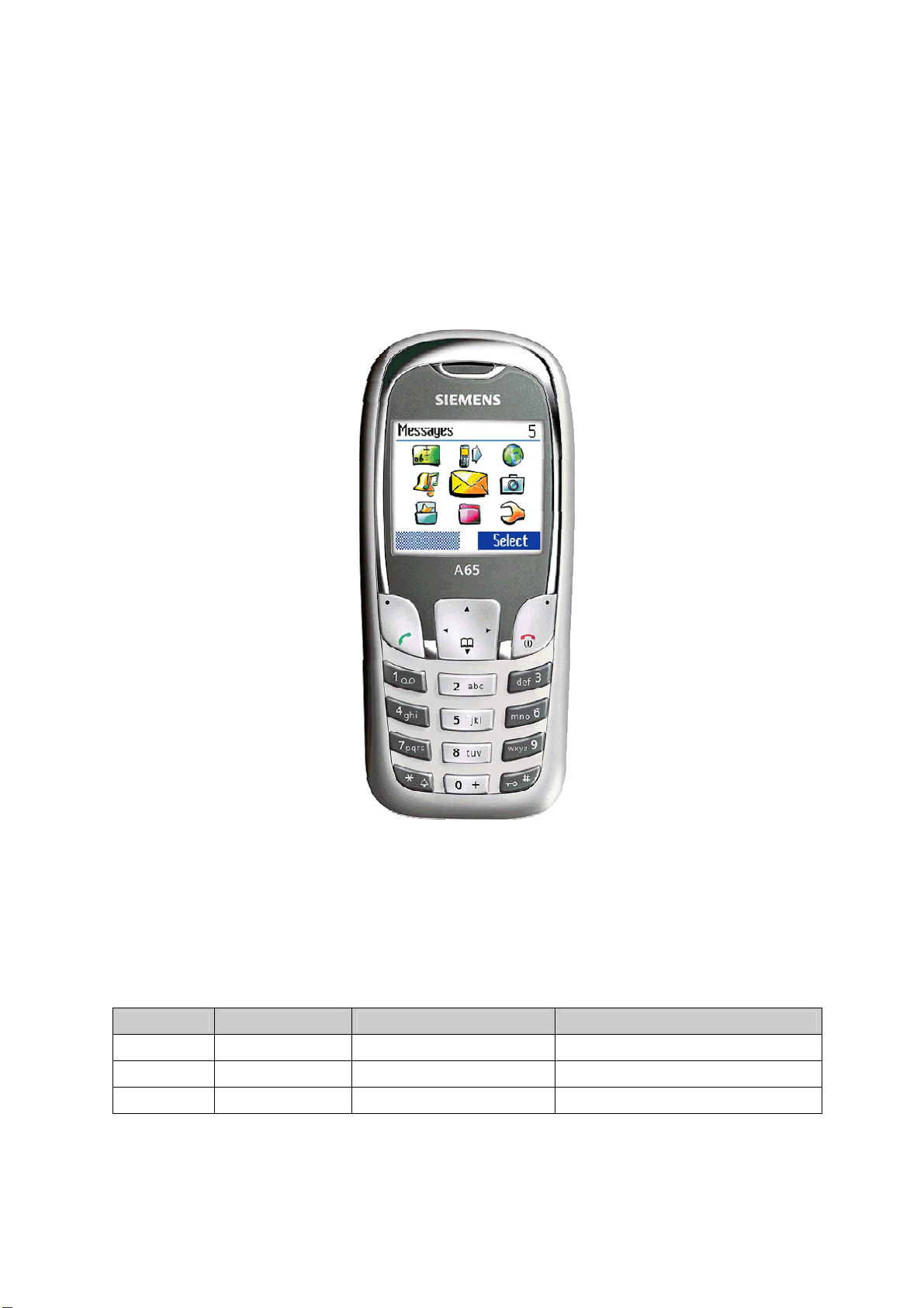
Level 2.5 – A62, A65
Release Date Department Notes to change
1.0 13.09.2004 ICM MP CCQ GRM T New document
1.1 13.12.2004 Com MD CC GRM T Document modified
Page
Service Repair Documentation
Level 2.5 – A62, A65
1 of 9
Page 2

s Com
Introduction
This Service Repair Documentation is intended to carry out repairs on Siemens repair level
2.5. The described failures shall be repaired in Siemens authorized local workshops only.
All repairs have to be carried out in an ESD protected environment and with ESD protected
equipment/tools. For all activities the international ESD regulations have to be considered.
Assembling/disassembling has to be done according to the latest A65 Level 2 repair
documentation. It has to be ensured that every repaired mobile Phone is checked according
to the latest released General Test Instruction document (both documents are available in
the Technical Support section of the C-market).
Check at least weekly C-market for updates and consider all A65 related Customer Care
Information
A62 Partnumber on IMEI label: S30880-S5890-#xxx
A65 Partnumber on IMEI label: S30880-S5810-#xxx
, while # may be any letter (A-Z) and xxx may be any number from 100, 101, 102....
If you have any questions regarding the repair procedures or technical questions spare not
hesitate to contact our technical support team in Kamp-Lintfort, Germany:
Tel.: +49 2842 95 4666
Fax: +49 2842 95 4302
e-mail: st-support@klf.siemens.de
Service Repair Documentation
Level 2.5 – A62, A65
Page
2 of 9
Page 3

s Com
Table of Content
1 A62, A65 board layout...................................................................................................................4
2 Connector SIM Card Reader .........................................................................................................5
3 Connector IO Jack.........................................................................................................................6
4 Connector Battery .........................................................................................................................7
5 Connector Display .........................................................................................................................8
6 LED_ KEYPAD_BACKLIGHT .......................................................................................................9
Service Repair Documentation
Level 2.5 – A62, A65
Page
3 of 9
Page 4

s Com
1 A62, A65 board layout
Jigs, Tools and Working materials for all described repairs:
- hot air blower
- soldering gun
- tweezers
- flux
- solder
Connector
BATTERY
Connector
IO JACK
Connector
DISPLAY
LED
Keypad Backlight
Connector
SIM CARD READER
Service Repair Documentation
Level 2.5 – A62, A65
Page
4 of 9
Page 5

s Com
2 Connector SIM Card Reader
okay
okay
not okay
okay
SCRAP has to be
send separately to
WSC
- check for twisted or
bended contacts
- check for dry joints
Level 2 Repair
Fault Symptoms
Customer: GRT:
Handset does not accept SIM card SIM Card Problems
SIM Card Problems
Watch for oxidation and
damaged pads of the SIM
card reader
not okay
Check the status of the
SIM card reader visually
Exchange
SIM Card reader
not okay
Use the resistor test
function of a multimeter
to check connection
between spring
contacts and soldering
contacts. The value
must be ~0Ω
Connector SIM Card Reader
Use soldering iron to remove defective component. Avoid excessive heat! Watch surrounding components!
Resolder new component afterwards.
E-commerce order number: L36334-Z97-C291
Soldering temperature: 240 - 255°C
IRIS Diagnose Code: 43300 Interface/SIM Cardreader/Mechanical Damage
Service Repair Documentation
Level 2.5 – A62, A65
Page
5 of 9
Page 6

s Com
3 Connector IO Jack
not okay
not okay
SCRAP has to be
send separately to
Clean
IO connector
- check for twisted or
bended contacts
- check for dry joints
Level 2 Repair
Fault Symptoms
Customer: GRT:
Charging Problems No connection to GRT
Problems with external loudspeaker or microphone when using a car kit Tbd.
Problems with accessories connected at the IO connector
IO connector Problems
Watch for oxidation and
damaged pads of the
IO connector
okay
Check for dust inside
the IO connector
not okay
Check the status of the
IO connector visually
okay
okay
Exchange
IO connector
not okay
Use the resistor test
function of a multimeter
to check connection
between spring
contacts and soldering
contacts. The value
must be ~0Ω
okay
Connector IO Jack
Use soldering iron to remove defective component. Avoid excessive heat! Watch surrounding components!
Resolder new component afterwards.
E-commerce order number: L36334-Z93-C303
Soldering temperature: 240 - 255°C
IRIS Diagnose Code: 46100 Interface/Charging Connector/Mechanical Damage
47300 Interface/Data Interface/Mechanical Damage
4B100 Interface/Headset Connector/Mechanical Damage
Service Repair Documentation
Level 2.5 – A62, A65
Page
6 of 9
Page 7

s Com
4 Connector Battery
okay
okay
not okay
okay
SCRAP has to be
send separately to
WSC
- check for twisted or
bended contacts
- check for dry joints
Level 2 Repair
Fault Symptoms
Customer: GRT:
Mobile does not switch on No connection to GRT
Battery connector
Problems
Watch for oxidation and
damaged pads of the battery
connector
not okay
Check the status of the
battery connector visually
Exchange
Battery connector
not okay
Use the resistor test
function of a multimeter
to check connection
between spring
contacts and soldering
contacts. The value
must be ~0Ω
Connector BATTERY
Use hot air blower to remove defective component. Avoid excessive heat! Watch surrounding components!
Resolder new component afterwards.
E-commerce order number: L36334-Z97-C213
Soldering temperature: 240 - 255°C
IRIS Diagnose Code: 13000 Battery/Mechanical Damage
Service Repair Documentation
Level 2.5 – A62, A65
Page
7 of 9
Page 8

s Com
5 Connector Display
Fault Symptoms
Customer: GRT:
Display problems, like missing lines or columns on
the LCD or display contrast problems or illumination
problems
Display connector
Problems
Watch for oxidation and
damaged pads of the display
connector
not okay
Check the status of the
display connector visually
Exchange
Display connector
not okay
Use the resistor test
function of a multimeter
to check connection
between spring
contacts and soldering
contacts. The value
must be ~0Ω
Connector DISPLAY
Use hot air blower to remove defective component. Avoid excessive heat! Watch surrounding components!
Resolder new component afterwards.
E-commerce order number: L36334-Z97-C205
Soldering temperature: 240 - 255°C
IRIS Diagnose Code: 21000 Display / Performance
22000 Display / Background Illumination
Display problems
okay
okay
not okay
okay
SCRAP has to be
send separately to
WSC
- check for twisted or
bended contacts
- check for dry joints
Level 2 Repair
Service Repair Documentation
Level 2.5 – A62, A65
Page
8 of 9
Page 9

s Com
6 LED_ KEYPAD_BACKLIGHT
okay
okay
Tbd.
not okay
okay
SCRAP has to be
send separately to
WSC
- check for dry joints
Level 2 Repair
Fault Symptoms
Customer: GRT:
Keypad BACKLIGHT illumination does not work
not okay
Exchange
Keypad LED
not okay
LED_ KEYPAD_BACKLIGHT
Remove metal dome sheet before replace LED’s Use soldering iron to remove defective component. Avoid
excessive heat! Watch surrounding components! Resolder new component afterwards. The metal dome jip
must be used to place the metal dome sheet.
E-commerce order number: L36
Soldering temperature: 240 - 255°C
IRIS Diagnose Code: 22000 Display / Background Illumination
LED’s Problems
Watch for oxidation and
damaged pads of the LED’S
Check the status of the
battery connector visually
Use the diode test
function of a multimeter
to check the status of
the diode. The typical
voltage drop on the
diode is 1.7 V when
testing the diode
function with the
multimeter.
840-L2056-D670
Service Repair Documentation
Level 2.5 – A62, A65
Page
9 of 9
 Loading...