

Siemens SRC-8 Installation Instructions Manual
Installation Instructions
+
Model SRC-8
Addressable 8-Output Relay Module
OPERATION
The Model SRC-8 module from Siemens
Industry, Inc., used with the SXL-EX System is
an 8-Output Programmable Relay Module that
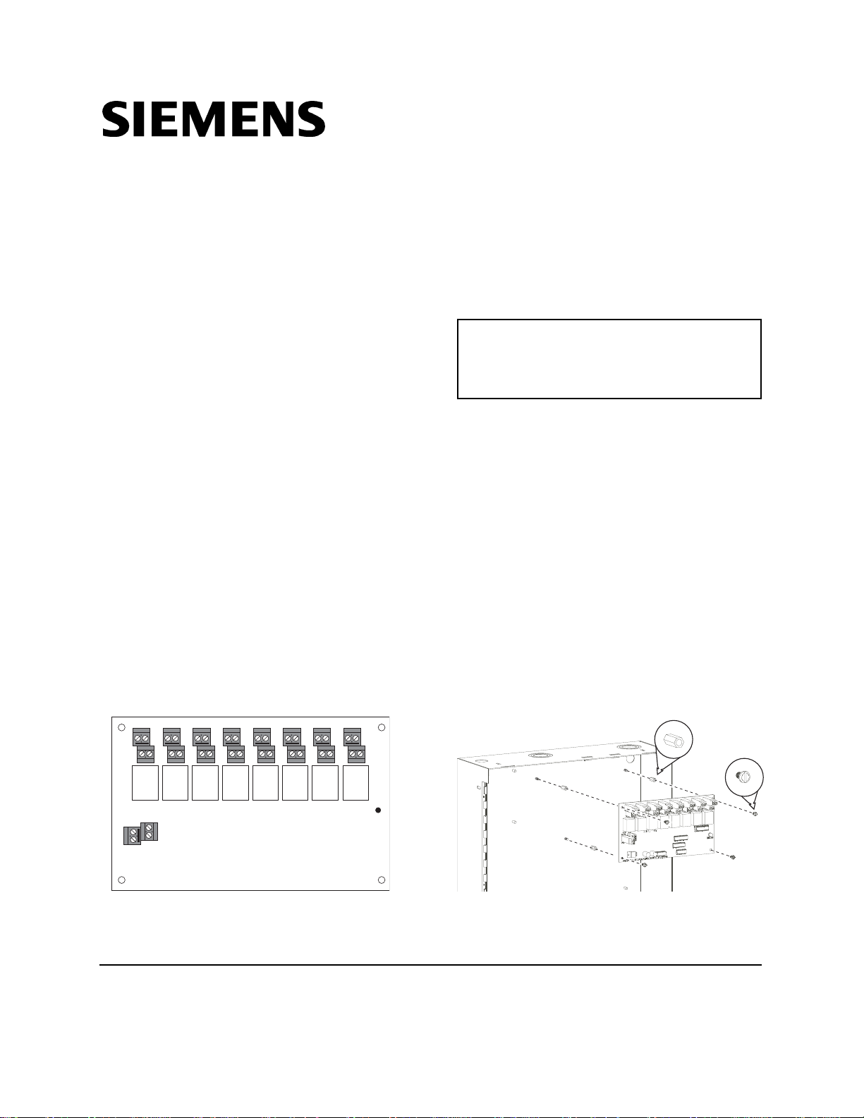
provides eight Form C relays. Terminal Block 9
(See Figure 1 below) provides a connection to
TB3 on the Main Board for a 24V regulated and
filtered power supply. Terminal blocks 1-8
provide the eight Form C relays.
If the green LED (labeled DS1) on the righthand side of the module is on, it indicates that
the module is active.
The SRC-8 causes a trouble on the display
panel when any of the following three conditions
occurs:
1. There is a short on the data line.
2. No SRC-8 module is connected to the
System, though there is an address for the
module in the System.
3. An SRC-8 module is connected to the
system, but there is no address for it in the
System.
TB1 TB2 TB3 TB4 TB5 TB6 TB7 TB8
CC
CC
C
N
NCN
N
O
C
RELAY 1 RELAY 2 RELAY 3 RELAY 4 RELAY 5 RELAY 6 RELAY 7 RELAY 8
TB9
-V
ER
Data
24V
CC
N
O
C
CC
NON
NCN
O
C
SRC-8
C
C
N
N
O
C
CC
CC
NON
NCN
O
C
C
DS1
N
O
POLL
INSTALLATION
Remove all System power before
installation, first battery and then AC.
(To power up, connect the AC first
and then the battery.)
In a New SXL-EX System
(Refer to Figure 2):
Install the SRC-8 in the upper right-hand
portion of the EN-SX enclosure by following the
steps listed below.
1. Insert the four 6-32 x 1/2 standoffs over the
four studs in the upper right-hand corner of
the SXL-EX enclosure as shown in Figure 2.
2. Place the SRC-8 board over the four
standoffs in the upper right-hand portion of
the EN-SX enclosure. Using the four 6-32
screws provided, fasten the SRC-8 board to
the standoffs.
4X
4X
Figure 1
SRC-8 Module
Siemens Industry, Inc.
Building Technologies Division
Florham Park, NJ
Siemens Building Technologies, Ltd.
Fire Safety & Security Products
2 Kenview Boulevard
Figure 2
Installing an SRC-8
Brampton, Ontario
P/N 315-092968-10
L6T 5E4 Canada
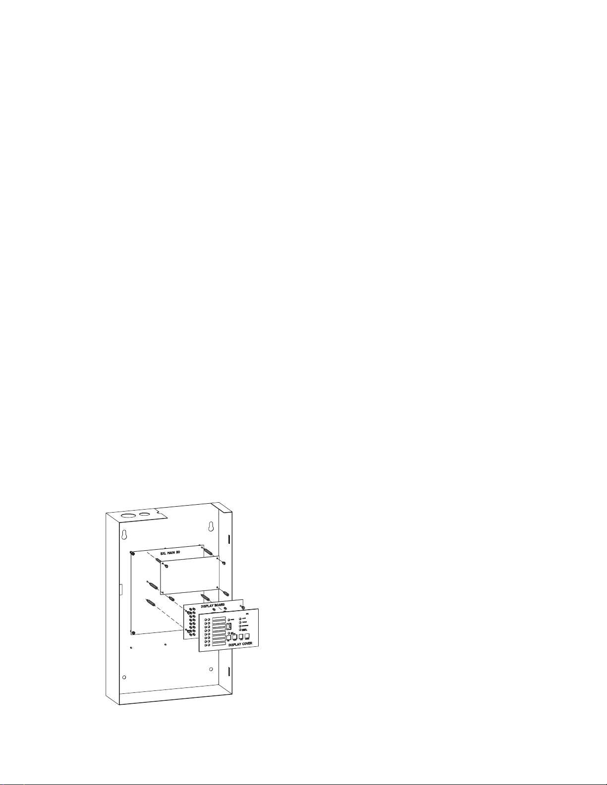
In an Existing SXL® System
(Refer to Figure 3):
To place the SRC-8 on the Main Board of an
existing system, first remove the existing Display
Board and its cover by following the steps below.
1. Remove the Display Cover from the Display
Board as shown in Figure 3. Discard its top
two standoffs.
2. Unplug the ribbon cable from the Display
Board at jumper JP4 on the Main Board.
3. Remove the Display Board from the SXL
Main Board by unscrewing the four 6-32
screws and setting them to one side.
4. Remove and discard the two standoffs that
were supporting the two upper corners of
the Display Board.
5. Next, install the SRC-8 by using the four 632 x 1-
7
/8 standoffs, the 6-32 screw, and the
two 15/16 standoffs provided as follows:
• Fasten the 1-7/8 nylon standoff provided to
the back of the upper left-hand corner of
the SRC-8 with the screw provided.
• Remove the screw from the upper right-
hand corner of the Main board.
• Screw another long standoff to the upper
right-hand corner of the Main board.
• Screw the last two long standoffs provided
to the Main board as shown in Figure 3.
• Place the SRC-8 module on the standoffs.
• Use the screw removed from the Main
board to secure the upper right-hand
corner of the SRC-8 board to the Main
board.
SRC-8
Figure 3
Installation in an Existing System
®
6. Fasten the two short standoffs remaining to
the bottom two corners of the SRC-8 board
(They are supports for the Display Board).
7. Once the SRC-8 is in place, re-install the
Display Board by reversing Steps 1-3 above.
PROGRAMMING
Use Program Level 9 to program the System to
supervise the SRC-8 module; and refer to the
SXL-EX Manual, P/N 315-095997, Program
Level 5, for programming the relay output
control matrix.
1. To enter the System:
a. Press the RESET and DRILL keys at
the same time.
b. Enter your password (Refer to Enter
Password under PROGRAM MODE in
the Manual).
c. Press the SILENCE key to confirm the
information for the system.
d. An A should display in the 7-segment
display.
e. If an F appears, repeat the process until
an A appears.
2. To enter the Program Mode:
a. Press the ACK key once.
b. Note that a P displays in the 7-segment
display.
c. Be sure the PROGRAM/TEST LED is lit.
3. To select the desired Program Mode level:
a. To select Program Level 9, press the
RESET button 9 times.
b. Press SILENCE.
4. To program the SRC-8:
a. Note the top zone status LEDs on the
display board.
• If the top red LED is on, the SRC-8 is
activated and sublevel -1 appears in
the display.
• If the top red LED is off, the SRC-8 is
not activated.
b. Press the DRILL key to toggle between
ON (activated) and OFF (de-activated)
as desired.
5. To exit the system:
a. Press the ACK key until an L appears
on the display.
b. Press SILENCE to exit the program.
2
 Loading...