

Page 1
573
4
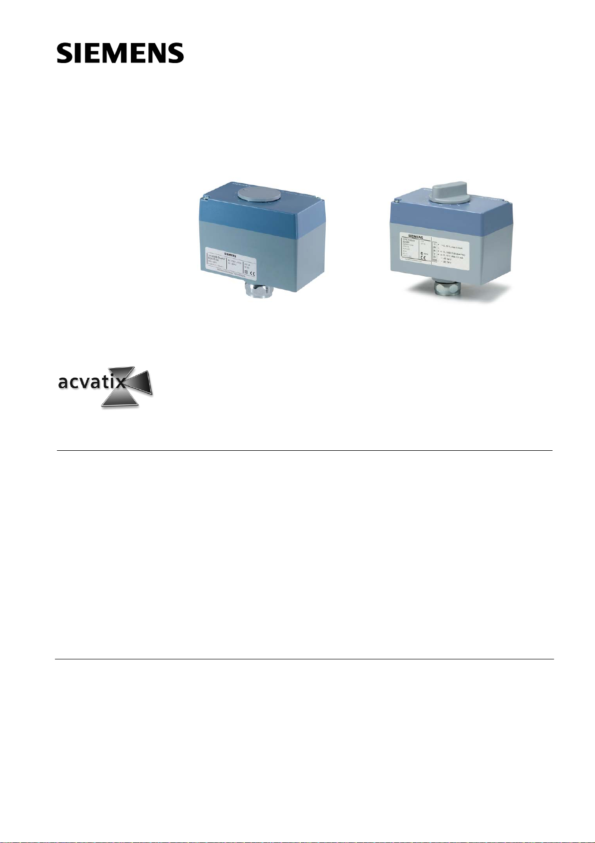
SQS35.50, SQS35.53,
SQS65.5
with spring return function, without manual adjuster
Electromotoric
Actuators
for valves with 5.5 mm stroke
• SQS35… operating voltage AC 230 V, 3-position control signal
• SQS85… operating voltage AC 24 V, 3-position control signal
• SQS65… operating voltage AC 24 V, DC 0…10 V, DC 2…10 V or 0…1000 Ω
• Positioning force 400 N
• Direct mounting on valves; no adjustments required
• Optional auxiliary switch for extra functions with SQS35.00, SQS35.03,
SQS85.00, SQS85.03
• With or without spring return function to DIN 32730
• Position indication
• Manual adjuster on actuators without spring return function
SQS35.00, SQS35.03,
SQS65, SQS65.2,
SQS85.00, SQS85.03
without spring return function, with manual adjuster
SQS35…
SQS85…
SQS65…
control signal
Use
CE1N4573en
09.09.2008
For operation of Siemens valves VVG44..., VVG55... and VXG44.... with 5.5 mm stroke
for water-side control of hot water and cooling water in heating, ventilation and air
conditioning systems.
In conjunction with the ASK30 mounting kit, the former Landis & Gyr-valves with 4 mm
or 5.5 mm stroke can also be operated: X3i..., VVG45..., VXG45..., VXG46..., VVI51....
Building Technologies
HVAC Products
Page 2
Type summary
Accessories
Order
Delivery
Example:
Type
reference
SQS35.00 150 s
SQS35.03 35 s
SQS35.50 150 s
SQS35.53
SQS65.5 Yes 8 s
SQS65
SQS65.2 DC 2…10 V
SQS85.00 150 s
SQS85.03
Operating
voltage
AC 230 V 3-position
AC 24 V
Positioning signal Positioning
DC 0…10 V
0…1000 Ω
3-position
time
35 s
35 s
35 s
Spring return
function
No
Yes 8 s
No
Spring
return time
Type reference Description For actuators Space for
ASC9.6
Auxiliary switch
Switching point adjustable
from 0...100 % stroke
4573Z04
SQS35.00, SQS35.03
SQS85.00, SQS85.03
1 x ASC9.6
When ordering, please give the quantity, product name, type reference, and any
accessories required.
20 actuators SQS35.00 and
20 auxiliary switch ASC9.6
Actuators, valves and accessories are supplied in separate packages.
Equipment combinations
Type reference DN PN class kvs [m3/h] Datasheet SQS35… SQS65… SQS85…
Function / mechanical design
The reversible synchronous motor is driven by a 3-position or a proportional
DC 0...10 V, DC 2...10 V or 0…1000 Ω control signal. The stroke is generated via an
antilocking gear train.
Design
Terminal strip,
auxiliary switch
VVG44... N4364
VXG44…
VVG55… 15...25 PN 25 0.25…6.3 N4379
4573Z03
15...40 PN 16 0.25…25
1
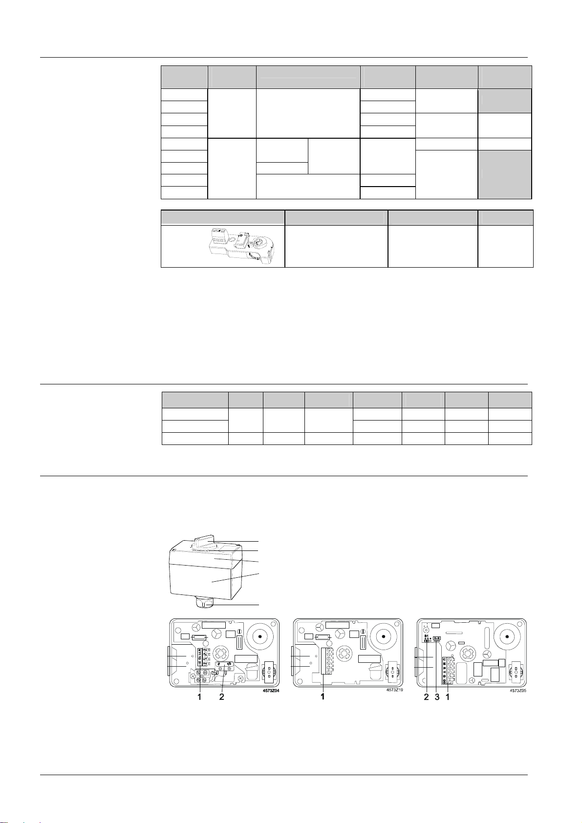
1 Manual adjuster
2
(SQS35.00, SQS35.03, SQS65, SQS65.2, SQS85.00, SQS85.03)
5
2 Position indication
4
3 Coupling nut for valve neck
4 Housing
5 Removable cover
3
G Y1 Y2 11 12L
N4464
9 9 9
9 9 9
9 9 9
SQS35...
1 Terminal strip
2 Auxiliary switch built-in as
standard in SQS35.50,
SQS35.53
2/8
Building Technologies Electromotoric Actuators CE1N4573en
HVAC Products 09.09.2008
SQS85...
1 Terminal strip
SQS65...
1 Terminal strip
2 «lin» / «log» connection
3 R − M bridge
Page 3
3-position
control signal
SQS35.50, SQS35.53
Spring return function
SQS65…
DC 0/2…10 V or
0…1000 Ω control
signal
SQS65.5
Spring return function
SQS65...
Selecting the flow
characteristic
Position of S1
• Voltage at Y1: Stem extends, valve opens SQS35…, SQS85…
• Voltage at Y2: Stem retracts, valve closes
• No voltage at Y1 or Y2: Actuator holds the current position
In the event of an AC 230 V power failure on terminal 21, the actuator will return
mechanically (return spring) to its 0 % stroke position within 8 seconds, closing the
valve. The Y positioning signal is not valued.
• The valve opens / closes in proportion to the control signal at Y or R.
• At DC 0/2 V or 0 Ω the valve is closed (A → AB).
• When power supply is removed, the actuator maintains its current position.
In the event of a power failure, the actuator will return mechanically (return spring) to its
0 % stroke position within 8 seconds, closing the valve. The Y positioning signal is not
valued.
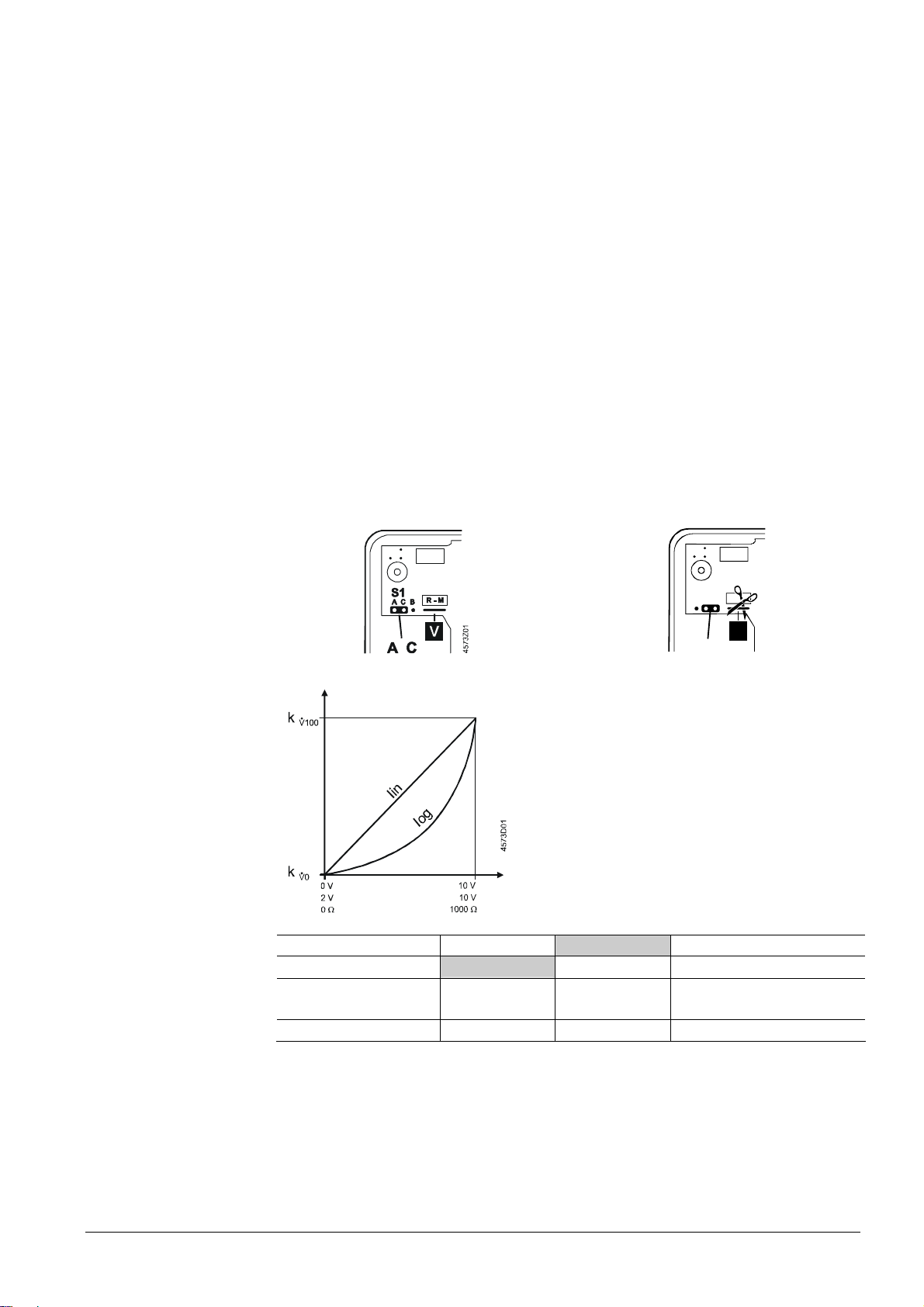
Connector S1 (under the cover, on the printed circuit board) can be repositioned to
change the flow characteristic of valves from «equal percentage» to «linear»; in all
cases the flow characteristic relates to the through-port of the valve.
S1 connected to A and C:
equal-percentage flow characteristic
S1 connected to B and C:
linear flow characteristic
(factory setting)
Flow characteristic
Priority of signals
Features and benefits
S1
R - M
A C B
Ω
Volumetric flow rate
Control
signal
Relationship between the DC 0…10 V,
DC 2…10 V or 0…1000 Ω control signal
and the volumetric flow rate
Control signals:
Y = DC 0...10 V or DC 2...10V
R = 0...1000 Ω; cut through R − M bridge
Flow characteristic
log = Equal-percentage valve characteristic
(factory setting)
lin = Linear valve characteristic
Flow range
k = Volumetric flow 100%
&
V100
k = Volumetric flow 0 %
&
V0
C B
4573Z02
Positioning signal Y DC 0/2…10 V DC 0/2…10 V
Signal R
Position / stroke The Y positioning
signal is valued.
Position feedback U DC 0…10 V DC 0…10 V DC 0…10 V
1)
Use with 0…1000 Ω signal indicator, e.g. frost protection. For details see connection diagram
0…1000 Ω
The R signal is
valued.
1)
0…1000 Ω 1)
Signal addition Y and R
• Electromotoric actuator, maintenance-free
• Reversible synchronous motor
• Antilocking gear train
• Load-dependent switch-off in stroke limit positions
3/8
Building Technologies Electromotoric Actuators CE1N4573en
HVAC Products 09.09.2008
Page 4
Engineering notes
The actuators must be electrically connected in accordance with local regulations and
the connection diagrams.
Caution
SQS65…
Mounting notes
Overview
Mounting Instructions
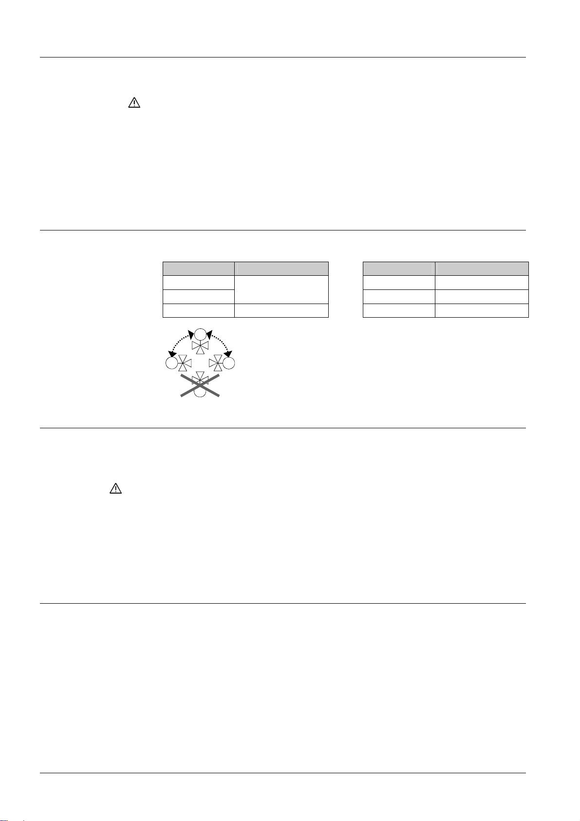
Orientation
Safety regulations and restrictions designed to ensure the safety of people and
property must be observed at all times.
With the SQS65… actuators, the connector used to select the flow characteristic
must be set to «lin» for valve types VVG55...
Admissible temperatures refer to «Technical data»
If an auxiliary switch is required, its switching point should be indicated on the plant
schematic.
Mounting Instructions are enclosed in the product packaging.
Type reference Mounting Instructions Type reference Mounting Instructions
SQS35… SQS65.5 M4573.3
SQS85…
ASC9.6 G4573.1 SQS65.2 M4573.5
M4573.7
SQS65 M4573.4
90°
90°
4362Z01
Commissioning notes
When commissioning the system, check wiring and the functions. In addition, select or
check the auxiliary switch settings.
Manual adjuster
Switching off the positioning signal.
The valve can be fully closed (= 0 % stroke) by turning the manual adjuster
counterclockwise. Control is automatically resumed when the positioning signal returns.
3-position control Every actuator must be driven by a dedicated controller (refer to «Connection
diagrams»).
Maintenance notes
The actuators are maintenance-free.
When servicing the actuator:
• Switch off pump and power supply
• Close the main shutoff valve in the pipework
• Release pressure in the pipes and allow them to cool down completely
• If necessary, disconnect electrical connections from the terminals
The actuator must be correctly fitted to the valve before recommissioning.
Repair
The actuator can not be repaired. It has to be replaced as a complete unit.
4/8
Building Technologies Electromotoric Actuators CE1N4573en
HVAC Products 09.09.2008
Page 5
Disposal
Warranty
Technical data
The device contains electrical and electronic components and must not be disposed of
together with domestic waste. This applies in particular to the PCB.
Legislation may demand special handling of certain components, or it may be sensible
from an ecological point of view.
Current local legislation must be observed.
The technical data relating to specific applications are valid only in conjunction with the
valves listed in this Data Sheet under «Equipment combinations».
The use of the actuators in conjunction with third-party valves invalidates all
claims under Siemens Switzerland Ltd / HVAC Products warranty.
SQS35.00
SQS35.03
SQS35.50
SQS35.53
SQS85.00
SQS85.03
SQS65
SQS65.2, SQS65.5
Power supply Operating voltage AC 230 V ± 15 % AC 24 V ± 20 %
Frequency 50 Hz 50 Hz 1)
Power consumption
SQS35.00:
2.5 VA
SQS35.03:
3.5 VA
End switches
switching capacity,
terminals 11 or 12
AC 250 V,
6 A res.
2.5 A ind.
SQS35.50:
5 VA
SQS35.53:
6 VA
2 VA
AC 250 V,
6 A res.
2.5 A ind.
SQS65, SQS65.2:
4.5 VA
SQS65.5:
7 VA
Signal inputs Terminals Y1, Y2 3-position
Terminal Y
SQS65, SQS65.5:
DC 0…10 V,
max. 0.1 mA
SQS65.2:
DC 2…10 V,
max. 0.1 mA
Terminal R 0…1000 Ω
Signal output Terminal U DC 0...10 V,
max. 0.5 mA
Parallel operation of
not possible max. 10
actuators
Operating data Positioning time in
control mode for
opening / closing
SQS35.00:
150 s
SQS35.03:
35 s
Positioning time with
spring return
8 s for closing
SQS35.50:
150 s
SQS35.53:
35 s
SQS85.00:
150 s
SQS85.03:
35 s
35 s
SQS65.5: 8 s for
closing
Positioning force 400 N
Nominal stroke 5.5 mm
Admissible
temperature
of medium in the valve
1…130 °C (short-time up to 150 °C)
Electrical connections Cable entry 2 openings ∅20.5 mm (for M20)
Norms and standards CE-conformity
EMC-directive
Immunity EN 61000-6-2 Industrial
2004/108/EC
2)
EN 61000-6-1
Residential
Low voltage directive 2006/95/EC
Emission EN 61000-6-3 Residential
Electrical safety EN 60730-1
5/8
Building Technologies Electromotoric Actuators CE1N4573en
HVAC Products 09.09.2008
Page 6
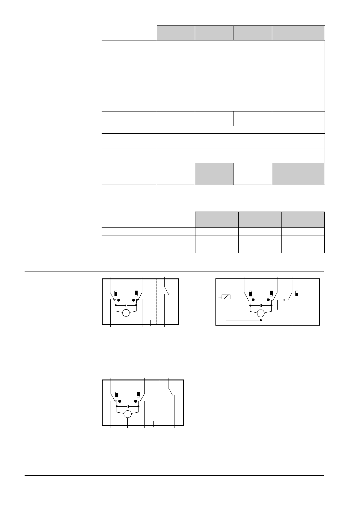
SQS35.00
SQS35.03
Housing protection
standard
IP54 to EN 60529
SQS35.50
SQS35.53
SQS85.00
SQS85.03
SQS65
SQS65.2, SQS65.5
Upright to
horizontal
Environmental
compatibility
ISO 14001 (Environment)
ISO 9001 (Quality)
SN 36350 (Environmentally compatible products)
RL 2002/95/EG (RoHS)
Dimensions / Weight Dimensions refer to «Dimensions»
Weight with
packaging
0.6 kg 0.7 kg 0.6 kg 0.6 kg
SQS65.5: 0,7 kg
Materials Actuator housing Plastics
Housing cover and
Plastics
manual adjuster
Gear train and stem
Plastics
with coupling
Accessories Auxiliary switch
ASC9.6
switching capacity
1)
For applications at 60 Hz use SQS65…U resp. SQS85…U actuators.
2)
Transformer 160 VA (e.g. Siemens 4AM 3842-4TN00-0EA0) for AC 24 V actuators
General
Operation
environmental conditions
AC 250 V,
3 A resistive
3 A inductive
AC 250 V,
EN 60721-3-3
3 A resistive
3 A inductive
Transport
EN 60721-3-2
Storage
EN 60721-3-1
Environmental conditions Class 3K5 Class 2K3 Class 1K3
Temperature –5...+50 °C –25...+70 °C –5...+50 °C
Humidity
5...95 % r.h. < 95 % r.h. 5...95 % r.h.
Internal diagrams
SQS35…
SQS85...
Y1 3Y2
100%
0%
M
∼
Cm1 Cm 2 c1
11 12NL45
4573G01
SQS35.00, SQS35.03
AC 230 V, 3-position, without spring return function
Cm1 End switch 100 % stroke
Cm2 End switch 0 % stroke
c1 ASC9.6 auxiliary switch can be fitted
L Potential-free auxiliary terminal
Y1 3Y2
100%
0%
M
∼
Cm1 Cm2 c1
11 12GL45
90190
21 Y1 Y2 H4
100%
n
Cm1 Cm2
0%
M
∼
NM
max. 50%
0%
c2
SQS35.50, SQS35.53
AC 230 V, 3-position, with spring return function
c2 Built-in auxiliary switch with fixed preset
minimum flow limit control (factory-fitted)
21 Spring return function
SQS85.00, SQS85.03
AC 24 V, 3-pos. without spring return function
Cm1 End switch 100 % stroke
Cm2 End switch 0 % stroke
c1 ASC9.6 auxiliary switch can be fitted
L Potential-free auxiliary terminal
4573G02
6/8
Building Technologies Electromotoric Actuators CE1N4573en
HVAC Products 09.09.2008
Page 7
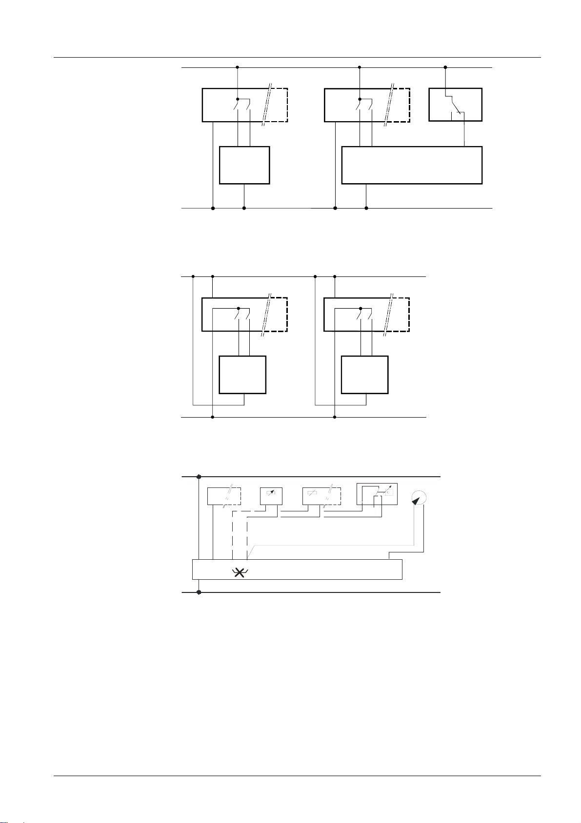
Connection diagrams
V
SQS35…
SQS85…
L
(L)
Q1
Q2
(N)
(Y1) (Y2)
Y1
AC 230 V
N
Y2
N
N1
Y1
N1, N2 Controller
Y1 Actuator SQS35.00, SQS35.03
Y2 Actuator SQS35.50, SQS35.53
L System potential AC 230 V
SP
(G)
Q1 Q2
(Y1)
(G0)
(Y2)
N1
(N)
(G)
(G0)
(L)
Q1
Q2
(Y1) (Y2)
Y1
Y2
N
11
N2
N System neutral
Q1, Q2 Controller contacts
F1 Maximum limiter
(spring return function)
4505A02
Q1 Q2
(Y1)
(Y2)
N2
4573A01
13
12
F1
21
Y2
SQS65…
Note
SN
AC 24 V
Y2Y1
G
Y1
Y2Y1
G
Y2
N1, N2 Controller
Y1, Y2 Actuator
SP System potential AC 24 V
SN System neutral
Q1, Q2 Controller contacts
SP
Y...
N1
RM MR
R1
F1
ϑ
1 32
P1F2
24
DC 0/2...10 V
0...1000 Ω
GG0YR
M
U
Y1
SN
4573A07
N1 Controller
Y1 Actuator
R1 Signal indicator with 0…1000 Ω output
F1 Frost protection monitor with 0…1000 Ω output
F2 Frost protection thermostat
Terminal: 1 – 3 frost hazard / sensor is interrupted (thermostat closes with frost)
1 – 2 Normal operation
P1 Position indicator DC 0…10 V
SP System potential AC 24 V
SN System neutral
If a device is connected to terminal R, the factory-fitted bridge across R – M on the
printed circuit board must be cut through.
7/8
Building Technologies Electromotoric Actuators CE1N4573en
HVAC Products 09.09.2008
Page 8
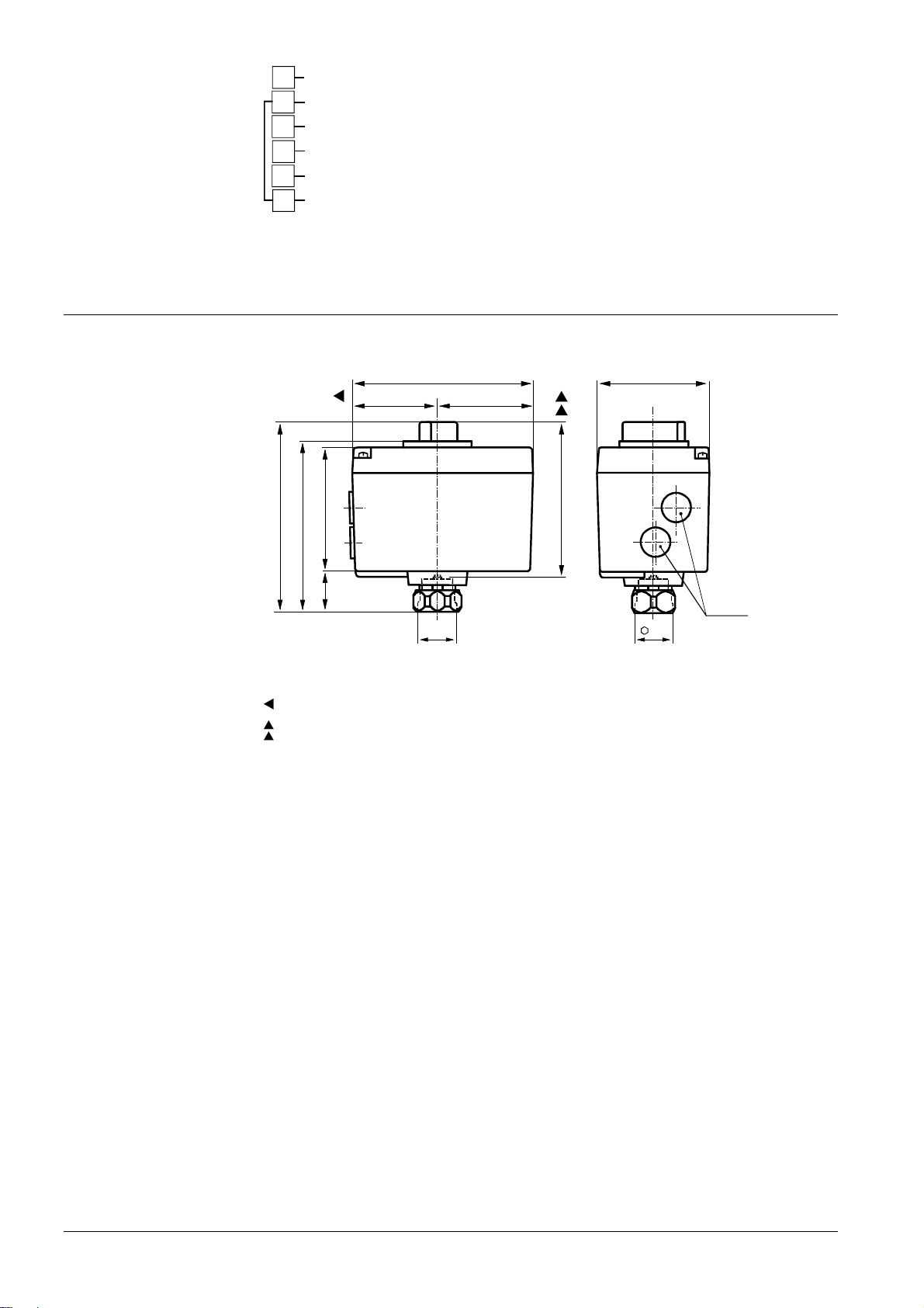
Connection terminals
n
SQS65…
Dimensions
U
Position indicator DC 0…10 V
M
Measuring neutral (= G0)
R
Signal input 0…1000 Ω
Y
Signal input DC 0…10 V (SQS65.2: DC 2…10 V)
Operating voltage AC 24 V: system potential SP
G
Operating voltage AC 24 V: system potential SN
G
0
4573Z06
Dimensions in mm
134
120
128
60 68
80
4579M01
111*
28 88
G¾"
Height of actuator after fitting on valve
*
> 100 mm Minimum clearance from wall or ceiling
> 200 mm for mounting, connection, operation, service etc
32
ø20.5
(M20)
8/8
Building Technologies Electromotoric Actuators CE1N4573en
HVAC Products 09.09.2008
© 2008 Siemens Switzerland Ltd Subject to alteratio
 Loading...