

Siemens SQS35.53, SQS65.5, SQS35.50, SQS35.03, SQS65.2 User Manual
...
Siemens Building Technologies CM1N4573E / 06.2001
Landis & Staefa D ivision 1/8
4
573
Electric actuators
for valves with
a 5.5 mm stroke
SQS35...
SQS65...
SQS85...
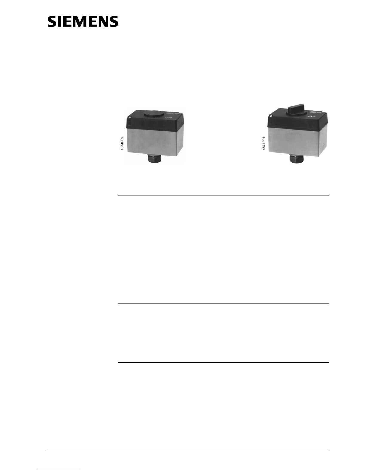
SQS35.50, SQS35.53 SQS35.00, SQS35.03, SQS65, SQS65.2
SQS65.5 SQS85.00, SQS85.03
with spring return / without manual adjustment without spring return / with manual adjustment
Electric actuators
• SQS35... AC 230 V operating voltage, 3-position control signal
• SQS85...AC 24 V operating voltage, 3-position control signal
• SQS65... AC 24 V operating voltage, DC 0 ...10 V or DC 2 ... 10 V control signal
• Positioning force 400 N
• Stroke 5.5 mm
• For direct mounting on valves, without adjustment
• Optional auxiliary switch for additional functions with SQS35.00, SQS35.03,
SQS85.00 and SQS85.03
• Choice of actuators
withorwithout
spring return function to DIN 32 730
• Non-spring return actuators
with
position indication and
with
manual
adjustment
• Spring return actuators
with
position indication and
without
manual
adjustment
Used to operate 2-port and 3-port valves with a 5.5 mm stroke. For valve types VVG44...,
VVG55..., VVP45..., VMP43..., VMP44..., VMP45..., VXG44..., VXP45...,VVI52...
• Area of application in accordance with IEC 721-3-3 Class 3K5
• Ambient temperatures:
− 5 ... + 50 °C
• Temperature of medium in the connected valve:+2 ...+130 °C
• The use of mounting kit ASK30 enables the following valves with a 4mm or 5.5 mm
stroke to be operated: X3i..., VVG45..., VXG45..., VXG46... and VVI51...
The reversible synchronous motor is driven with a 3-position control signal (SQS35…
and SQS85…) or a proportional DC 0…10 V (SQS65, SQS65.5) or DC 2...10 V
(SQS65.2) control signal. The corresponding stroke is generated via an anti-locking
gear mechanism.
3-position control at terminals Y1 or Y2:
• Voltage at Y1: Valve stem retracts, through-port opens
• Voltage at Y2: Valve stem extends, through-port closes
• No voltage at Y1 or Y2: Valve stem holds current position
Application
Functions
3-position or proportional
control signal
CM1N4573E / 06.2001 Siemens Building Technologies
2/8 Landis & Staefa Division
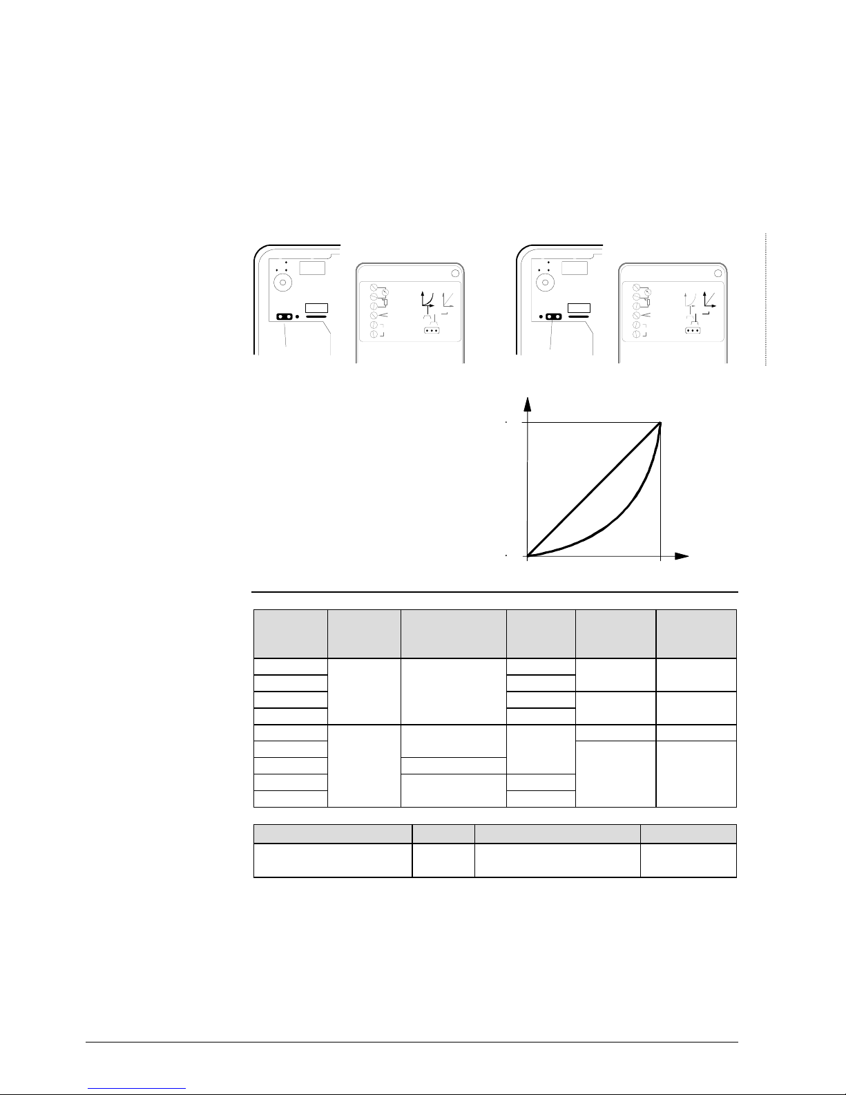
Connector S1 (under the cover, on the printed circuit board) can be repositioned to
change the flow characteristic of valves with a 5.5 mm stroke from “equal percentage” to
“linear”; in all cases the flow characteristic relates to the through-port of the valve.
• Connecting S1 to pins A and C produces an equal percentage f low characteristic
(factory setting), primarily for heating applications
• Connecting S1 to pins B and C produces a linear flow characteristic,
primarily for cooling applications
• For automatic operation, S1 must be connected either to pins A and C, or B and C,
depending on the required flow characteristic.
S1 connected to: AandC
(equal-percentage flow characteristic)
S1 connected to: CandB
(linear flow characteristic)
ACB
V
U
Y
V
U
Y
01161
R-M
ACB
S1
U
M
R
Y
G
G0
0...10Vmax.0,5mA
0..-1kW
0...10V-
0...1mA
24V~
AC
ACB
V
U
Y
V
U
Y
01162
R-M
ACB
S1
U
M
R
Y
G
G0
0...10Vmax.0,5mA
0..-1kW
0...10V-
0...1mA
24V~
CB
Relationship between the DC 0…10 V
or DC 2…10 V control signal and the
volumetric flow rate
Control signals:
Y = DC 0 ...10 V or DC 2...10V
R = 0...1000 Ω
Flow characteristic
log = Equal-percentage valve characteristic
(factory setting)
lin = Linear valve characteristic
Flow range
k
V100
= Volumetric flow 100%
k
V0
= Volumetric flow 0 %
Volumetric flow rate
l
i
n
l
o
g
4573D01
k
V100
k
V0
0V
2V
10 V
10 V
Controlsignal
Type Operating
voltage
Type of control
(Control signal)
Run-time
[s]
Spring-
return
function
Spring-
return time
[s]
SQS35.00
150 No ---
SQS35.03
AC 230 V 3-position 35
SQS35.50
150 Yes 8
SQS35.53
35
SQS65.5
DC 0...10 V Yes 8
SQS65
35
SQS65.2
AC 24 V DC 2...10 V No ---
SQS85.00
3-position 150
SQS85.03
35
Name Type For actuators Space for
Auxiliary switch ASC9.6
SQS35.00, SQS35.03
SQS85.00, SQS85.03
1 x ASC9.6
When ordering, please specify the quantity, product name, type, and any accessories
required.
Example:
1 actuator, type SQS35.00 and 1 auxiliary switch type ASC9.6
The actuator, valve and accessories are packed separately and not assembled prior to
delivery.
SQS65...
Selecting the flow
characteristic
Position of S1
Flow characteristic
Types
Accessories
Ordering
Delivery
Siemens Building Technologies CM1N4573E / 06.2001
Landis & Staefa Division 3/8
The following 5.5 mm stroke, threaded two-port and three-port valves can be operated
with electric actuator types SQS35... , SQS65... and SQS85...
Type DN [mm] PN [bar] Data sheet
Two-port valves
VVG44...
15 ... 40 16
N4364
VVP45...
10 ... 20 16
N4845
VMP43...(2)
15, 20 16
N4841
VMP44...(2)
15, 20 16
N4844
VVG55...
15 ... 25 25
N4379
VVI52...
15 25
N4377
Three-port valves
VXG44...
15 ... 40 16
N4464
VXP45...
10 ... 20 16
N4845
VMP43...
15, 20 16
N4841
Three-port valves with bypass "T"
VMP45...
10 ... 20 16
N4845
VMP43...(4)
15, 20 16
N4841
VMP44...(4)
15, 20 16
N4844
The admissible differential pressure values ∆p
max
and ∆psfor the complete motorised valve are shown in
the relevant valve data sheets.
• Electric actuator, no maintenance required
• Reversible synchronous motor
• Anti-locking gear mechanism
• SQS35.50, SQS35.53, SQS65.5 have spring return function to DIN 32730
• Load-dependent switch-off in stroke limit positions
• Selectable flow characteristic:equal percentage or linear for SQS65… actuators in
conjunction with valve types VVG44..., VVI52... and VXG44...
• Directly impacting manual adjustment for all non-spring-return ac tuators: SQS35.00,
SQS35.03, SQS65, SQS65.2, SQS85...
• Position indicator on all SQS35..., SQS65..., SQS85... actuators
• Accommodation for auxiliary switch type ASC9.6 on the SQS35.00, SQS35.03,
SQS85.00 and SQS85.03 actuators. An auxiliary switch (
not
the ASC9.6) is built in
as standard in actuator types SQS35.50 and SQS35.53 actuators.
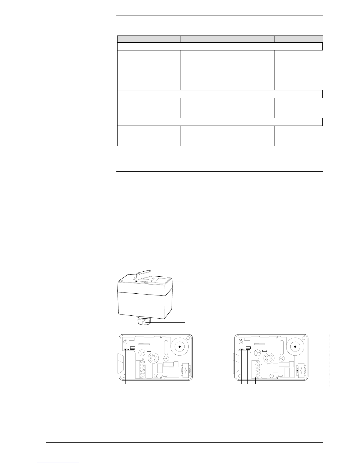
3
1
2
4573Z03
SQS35.00, SQS35.03
SQS65, SQS65.2
SQS85...
1 Manual adjustment
2 Position indication
3 Coupling bolt for valve neck
675
01163
UMRYGG0
R-M
ACB
S1
675
01163
UMRYGG0
R-M
ACB
S1
SQS35..., SQS85...
5 Terminal strip
6 Auxiliary switch built-in as standard in
SQS35.50 and SQS35.53
SQS65...
5 Terminal strip
6 «lin» / «log» connection
7 BridgeR −
−−
− M
Compatibility
Mechanical design
Manual adjustment
Terminal strip, auxiliary
switch etc.
 Loading...