

Siemens SQM50 series Installation Instructions Manual
Installation Instructions
Document No. 129-401
January 18, 2008
SQM5… Reversing Actuators, with Multiple Analog Control Input
Signals
Product Description
Reversing actuator used to position flow control
valves, butterfly valves, dampers, or any application
requiring rotary motion with multiple analog input
signals.
Product Numbers
SQM5x.xxxRxZx for 4 to 20 mA, 0 to 135 ohm and
0 to 10 Vdc input signals
Actuator Torque:
SQM50.2… 90 in/lb
SQM50.3… 90 in/lb
SQM50.4… 140 in/lb
SQM53.4… 200 in/lb
SQM56.5… 310 in/lb
SQM56.6… 400 in/lb
SQM… motors allow torque on either end of the
AGA58.3 and AGA58.4 shafts.
NOTE: For detailed information, see Technical
Instructions (155-517P25).
Max Shaft Torque:
AGA58.1 200 in/lb
AGA58.3 220 in/lb
AGA58.4 270 in/lb
AGA58.7 400 in/lb
Caution Notations
CAUTION:
Equipment damage may occur
if you do not follow the
procedures as specified.
Installation
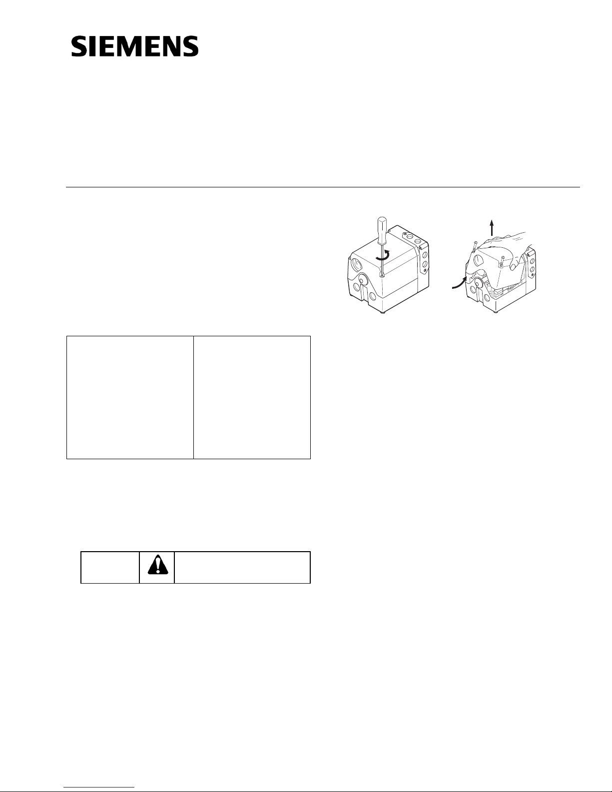
Cover Removal
EA0564R1
Figure 1. Figure 2.
EA0568R1
Rotational Direction Verification
Actuator model numbers that end with “R” are
factory configured for clockwise (cw), minimum to
maximum rotation when facing the gear end of the
actuator, or counterclockwise (ccw) rotation when
facing the other end of the actuator. The gear end of
the actuator is the side opposite of the visual
position indicator.
Actuator Mounting
SQM5… actuators can be mounted in any
orientation. Optional base mounting brackets are
available.
SQM5… actuators can also be face mounted using
self-tapping screws in combination with the various
holes on the face of the actuator gear end.
Switch Adjustment
SQM5…actuators are factory-wired with Switch I
(maximum), Switch II (fully closed/economy position)
and Switch III (minimum/low-fire). The individual
switch cams I, II, and III are factory set to 90°, 0°
and 10°, respectively. See Figures 3 and 4.
Use a Phillips screwdriver to loosen the two screws
on the actuator cover corners. See Figure 1.
Lift the screws and raise the cover. See Figure 2.
Item Number 129-401, Rev. DA Page 1 of 6
Document No. 129-401
Installation Instructions
January 18, 2008
EA0561R3
ACTUATOR
POSITION SCALE
ACTUATOR POSITION
INDICATING POINTER
CAM DRUM
RELEASE BUTTON
GEAR END
SWITCH CAM I
SET AT MAXIMUM
SWITCH CAM II
SET AT ZERO ("ECONOMY")
50
10
0
30
10
30
10
0
50
0
70
SINGLE SWITCH
CAM POINTER
DOUBLE SWITCH CAM POINTER
SWITCH CAM III
SET AT MINIMUM
50
30
10
0
0
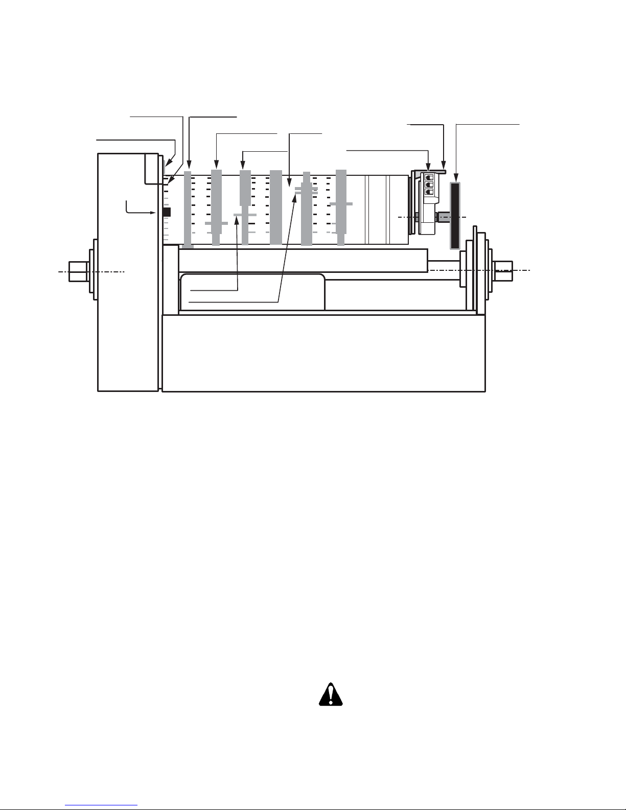
Figure 3. Component Identification on the Cam Drum Side of the SQM5…Actuator.
NOTE: The single switch cam pointers are used
together with the black scales when
configured for ccw operation.
The double switch cam pointers are used
together with the red scales when
configured for cw operation.
The individual switch cams can be adjusted by hand
or with the use of the tool attached to the outside of
the hinged switch terminal protection lid.
The adjustable range of the switches is limited by
the potentiometer range.
SQM5x.xxxRxZ3 actuators have a 90° potentiometer
and the switches must be adjusted between 0° and
90°.
SQM5x.xxxRxZ4 actuators have a 135°
potentiometer and the switches must be adjusted
between 0° and 135°.
Shaft Adjustment
The actuator shaft can be disengaged by pressing
the silver shaft release button. The shaft release
button is located above the grounding screw, under
the hinged terminal protection cover, and to the right
of the auto/manual switch. After pressing the shaft
release button in and slightly upward, the shaft can
ACTUATOR POSITION
CAM DRUM
ASZ... (1000 Ohm)
FEEDBACK POTENTIOMETER
50
30
10
0
0
DIAL POINTER
INDICATING DIAL
be manually rotated. After the shaft has been
manually aligned to the closed position, re-engage
the shaft by pushing the shaft release button
downwards.
Cam Drum Adjustment
Once the shaft has been set to the closed position,
the cam drum must be manually aligned by pressing
and holding the black cam drum release button (see
Figure 3). Rotate the cam drum until the “0” mark on
the actuator position scale (left scale on the cam
drum) is aligned with the gray actuator position
indicating pointer.
Position Indicating Dial Adjustment
The actual position of the SQM5… actuator is
indicated by the gray actuator position indicating
pointer (see
by the indicating dial through the housing’s window.
Ensure that the actuator position indicating dial is
aligned with the actuator position scale. If
necessary, rotate the dial in the clockwise direction.
Figure 3). The position is also displayed
CAUTION:
Turning the dial in the counterclockwise
direction may loosen the potentiometer
locking screw.
Page 2 of 6 Siemens Building Technologies, Inc.
 Loading...