

Siemens SQM45,SQM48.497A9,SQM48.697A9,SQM48 Series,SQM45.291A9,SQM45.295A9 Series Manual
CC1N7814en
31.10.2002
Siemens Building Technologies
HVAC Products
ISO 9001
7
814
Actuators
SQM45...
SQM48...
for air dampers and control valves of oil and gas burners
Electromotoric actuators
· Torques: – SQM45... up to 3 Nm
– SQM48... up to 20 Nm
– SQM48.6... up to 35 Nm
· Running times:
1)
– SQM45... 10 ... 120 s
– SQM48... 30 ... 120 s
– SQM48.6... 60 ... 120 s
1)
Depending on the basic unit (LMV...)
· Versions: – Choice of drive shafts (refer to «Type summary»)
The SQM45... / SQM48... and this Data Sheet are intended for use by OEMs which
integrate the actuators in their products!
Use
The actuators of the SQM45... / SQM48... range are used to drive gas dampers, air
dampers, oil control valves and other ancillary equipment.
When used in connection with burner controls or electronic fuel / air ratio control, the
associated controlling elements are controlled depending on burner output.
2/8
Siemens Building Technologies CC1N7814en
HVAC Products 31.10.2002
Warning notes
To avoid injury to persons, damage to property or the environment, the following
warning notes should be observed!
Do not open, interfere with or modify the actuators!
· Ensure protection against electric shock hazard by providing adequate protection
for the connection terminals
· Check to ensure that wiring is in an orderly state and that the wires are firmly con-
nected
Mounting notes
· Ensure that the relevant national safety regulations are complied with
· The connection between actuator drive shaft and controlling element must be rigid
with no mechanical play
Possible connection with drive shaft or hub:
· Groove with Woodruff key
· Drive shaft with flat edge and matching counterpiece
To avoid inadmissible loads on bearings caused by rigid hubs, it is recommended to
use compensating clutches with no mechanical play (e.g. metal bellows clutches).
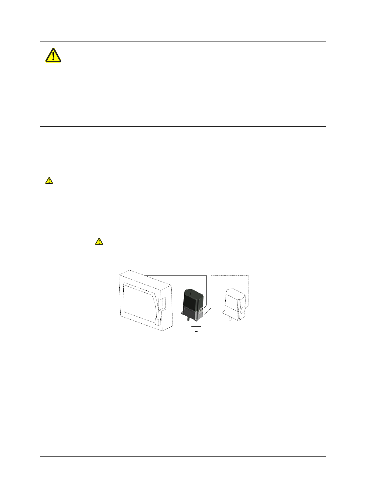
Only the specified cable may be used (refer to Basic Documentation P7550). The cable’s shielding must be connected to the printed circuit board using the tab provided.
Ensure that the actuator’s housing is connected to functional earth (FE) of the system.
If necessary, remove isolating layers of paint from the fixing points on the burner’s
casing or run separate earth wires.
For detailed information, refer to «Installation Inctructions for the LMV5x system»
J7550.1.
CAN bus
AGG5.6...
SQM4...
FE
B
a
s
i
c
u
n
i
t
L
M
V
5
.
.
.
7814z03e/0502
The working range is given on the type field and must be observed when mounting the
actuator. To ensure the actuator is accurately located on the burner, a positioning pin of
6 mm diameter must be fitted on the mounting surface.
Positive connection
Cable and cable
shielding
Working range of
actuator
3/8
Siemens Building Technologies CC1N7814en
HVAC Products 31.10.2002
To ensure degree of protection IP 54, suitable Pg glands must be fitted in the actuator’s Pg11 openings.
The Pg glands used must feature cable strain relief.
To ensure degree of protection IP 54 during the actuator’s entire service life, the bearing of the drive shaft must be located such that it will not be directly exposed to water or
dust.
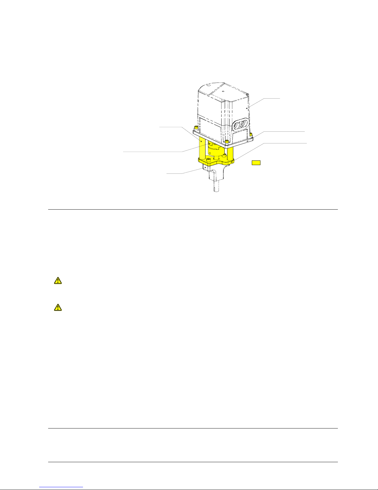
SQM4...
Mounting plate SQM4...
Secure coupling piece to drive shaft
such that intermediate plastic
piece has an axial play of about
0.2 to 0.5 mm
Mounting plate VKF41...
Spacer
VKF41...
7814z02e/0502
ASK33.4
Installation notes
· Installation work must be carried out by qualified staff
· Always run the high-voltage ignition cables separate from the unit and other cables
while observing the greatest possible distance
· To ensure protection against electric shock hazard, make certain that the AC 230 V
section of the SQM4... is strictly segregated from the functional low-voltage section
· The holding torque is reduced when the actuator’s power supply is switched off
The housing cover may only be removed for short periods of time for wiring or when
making the addressing. It must be made certain that dust or dirt will not get inside the
actuator while such work is carried out.
The actuator contains a printed circuit board with ESD-sensitive components.
The top side of the board carries a cover which affords protection against direct contact. This protective cover may not be removed! The underside side of the board may
not be touched.
Addressing (assignment of functions) defines whether the SQM4... shall operate as a
· fuel actuator
· air damper actuator, or
· auxiliary actuator,
and is made with the display and operating unit AZL... and the addressing button on the
actuator, which is located under the housing cover (refer to Basic Documentation
P7550).
The correct assignment of actuator functions can be checked with the help of flashing
LEDs.
For the maximum permissible cable length, refer to the Basic Documentation.
Cabling must be strictly serial (no branching permitted!).
Commissioning notes
· Commissioning work must be carried out by qualified staff
IP 54
Mounting example
Housing cover
ESD
Addressing
Cable length
Topology
 Loading...