

Page 1
Building Technologies
505
.
4
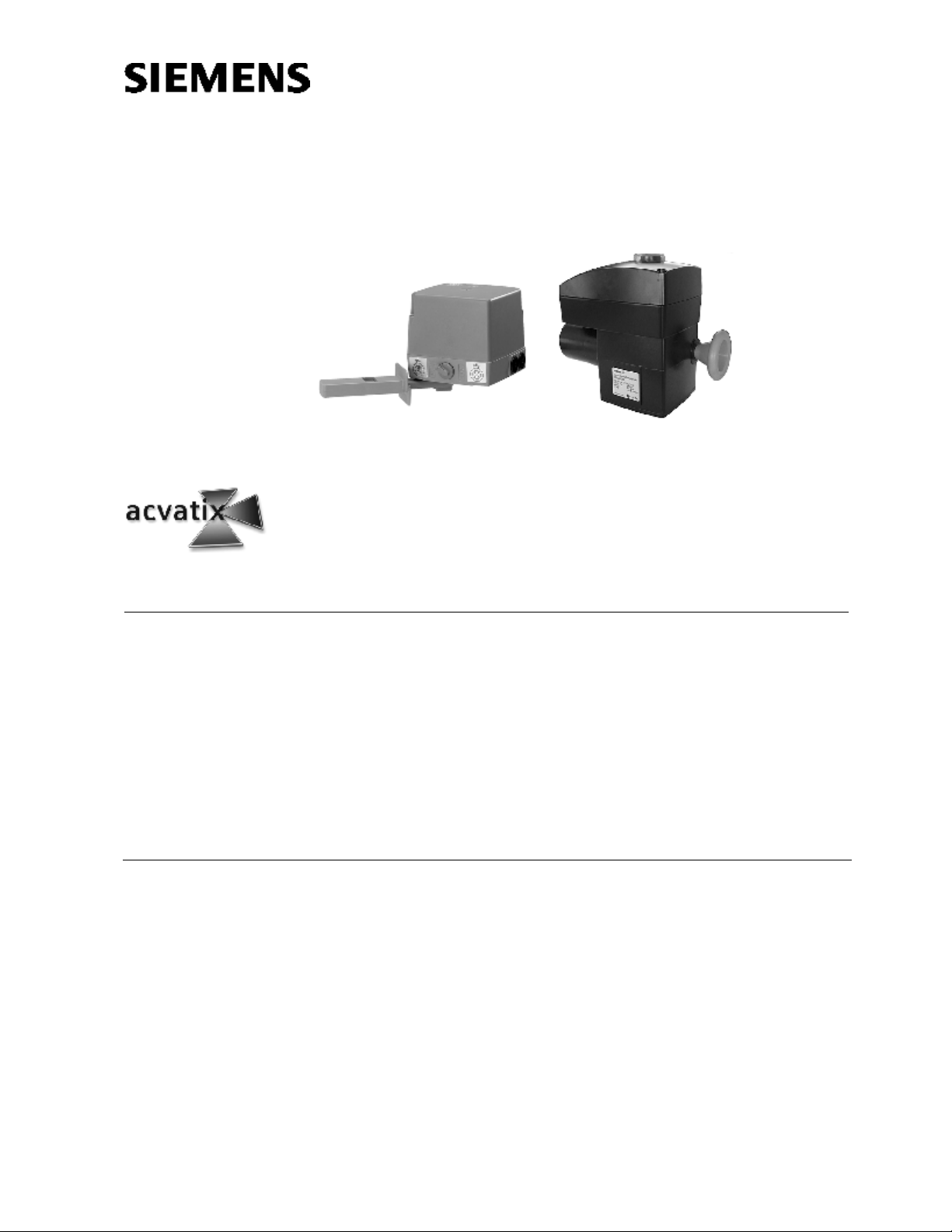
SQL35.00
SQL85.00
Electromotoric
Actuators
for VKF46…, VKF46 …TS butterfly valves
• SQL35.00, SQL36E… operating voltage AC 230 V, 3-position control signal
• SQL85.00 operating voltage AC 24 V, 3-position control signal
• Nominal angle of rotation 90°
• Auxiliary switch and potentiometer for extra functions
• Manual adjuster and position indicator
• SQL36E… built-in heating element to avoid condensation
• SQL36E… compatible with EN ISO 5211 flanges
• SQL36E… variable positioning time with SEZ31.1 auxiliary module
Use
SQL36E…
SQL35.00
SQL85.00
SQL36E…
.
CA1N4505en
26.10.2006
For operation of VKF41…, VKF46… and VKF46…TS butterfly valves as control and
shutoff valves in heating, ventilation and air conditioning plants.
HVAC Products
Page 2
Type summary
. . . . . . . . . . . . . . . . . . . . . . . . . . . . . . . . . . . . . . . .
Accessories
Type Operating
voltage
SQL35.00 AC 230 V
SQL85.00 AC 24 V
SQL36E50F04
SQL36E50F05
F04
3-position
SQL36E65 AC 230 V
Positioning
signal
6 s 30…180 s 100 Nm F07
Positioning time for 90°
at 50 Hz
without
SEZ31.1
125 s
25 s
with SEZ31.1
Positioning
force
20 Nm
40 Nm
Flange
connection
EN 5211
F05
SQL36E110 12 s 60…360 s 400 Nm F10
SQL36E160 24 s 120…720 s 1200 Nm
1)
EN 5211 F12 / F16 flange connections for third-party actuators are available on request.
1)
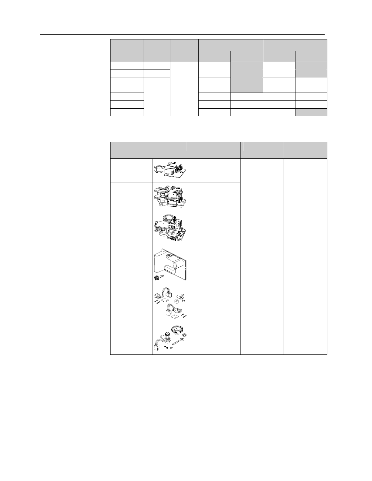
Type Description For actuators Mounting
position
ASC9.5
ASC9.4
ASZ7.4
Auxiliary switch
4554Z04
Double auxiliary
switch
4554Z06
Auxiliary switch and
potentiometer 1000 Ω
45 54 Z05
SQL35.00
SQL85.00
1 x ASC9.5 or
1 x ASC9.4 or
1 x ASZ7.4
(only one
accessory at a
time can be
mounted)
.
Order
Delivery
Example:
SEZ31.1
Auxiliary module for
4505Z10
variable positioning
time (refer to
«Function/mechanical
SQL36E65
SQL36E110
SQL36E160
design», page 4)
ASC36
4505Z19
Double auxiliary
switch
SQL36E50F04
SQL36E50F05
1 x SEZ31.1 and
1 x ASC36 and
1 x ASZ36
SQL36E65
Ω
ASZ36
0...1000
Potentiometer 1000 Ω
SQL36E110
SQL36E160
4505Z28
The actuator, butterfly valve, mounting kit and any accessories must be ordered
separately.
When ordering please specify the quantity, product name and type code.
1 actuator, type SQL35.00, 1 mounting kit, type ASK35.1 and
1 auxiliary switch with potentiometer, type ASZ7.4
The actuator, butterfly valve, mounting kit and accessories are packed separately and
delivered as individual items.
2/12
Building Technologies Electromotoric Actuators CA1N4505en
HVAC Products 26.10.2006
Page 3
Equipment combinations
4
5
0
5
Z
3
5
. . . . . . . . . . . . . . . . . . . . . . . . . . . . . . .
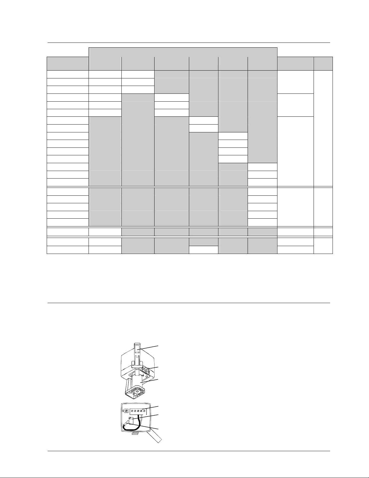
Electromotoric actuators
Butterfly valves
SQL35.00
SQL85.00
VKF46.40
VKF46.50
VKF46.65
VKF46.80
VKF46.100
ü ü
ü ü
ü ü
ü
ü
VKF46.125 ü
VKF46.150
VKF46.200
VKF46.250
VKF46.300
VKF46.350
VKF46.400
VKF46.450
VKF46.500
VKF46.600
VKF46.350TS
VKF46.400TS
VKF46.450TS
VKF46.500TS
VKF46.600TS
VKF41.150…200
VKF45.40… 125
VKF45.150…200
2)
2)
ü
ü
ü + ASK35
SQL36E50F04
1)
SQL36E50F05
1)
SQL36E65 SQL36E110 SQL36E160 Mounting kit
ASK35.1
ü
ü
ü
ASK35.2
ü
ü
N4136
ü
ü
ü
ü
Direct mounting
ü
ü
ü
ü
ü
ü
Direct mounting
ü
ü
ü
1)
SQL36E50… actuators can be mounted directly on VKF46… butterfly valves.
2)
VKF45… butterfly valves were replaced by VKF46… butterfly valves in 2000. For actuator
ASK35
ASK35
Direct mounting
Data
sheet
N4136
N4131
N4135
retrofitting on installed butterfly valves, replacement of actuators or ASK35:
− VKF45.40…125: Use SQL35.00 / SQL85.00 actuators and ASK35
− VKF45.150…200: Mounting of SQL36E65 actuator recommended
.
Function / mechanical design
The actuator is driven by a 3-position signal from the controller and generates a rotary
motion which is transferred via a driver to the valve.
SQL35.00
SQL85.00
These electromotoric actuators require no maintenance. They have a reversible
synchronous motor and reduction gears with self-lubricating sinter bearings.
1
1 Manual lever
2 Rotary «AUTO» / «MAN» selector
2
3 Yoke
When the selector is set to «MAN», the butterfly valve
3
can be operated with a manual lever. For manual
operation, the angle of rotation is mechanically limited by
an end stop.
4 Terminal strip
5 Double end switch (always factory-installed)
1211Y2Y1N
4
(G)
5
6 Plug for reversing direction of rotation
6
4505Z36
Building Technologies Electromotoric Actuators CA1N4505en
HVAC Products 26.10.2006
3/12
Page 4
SQL36E...
. . . . . . . .
. . . . . .
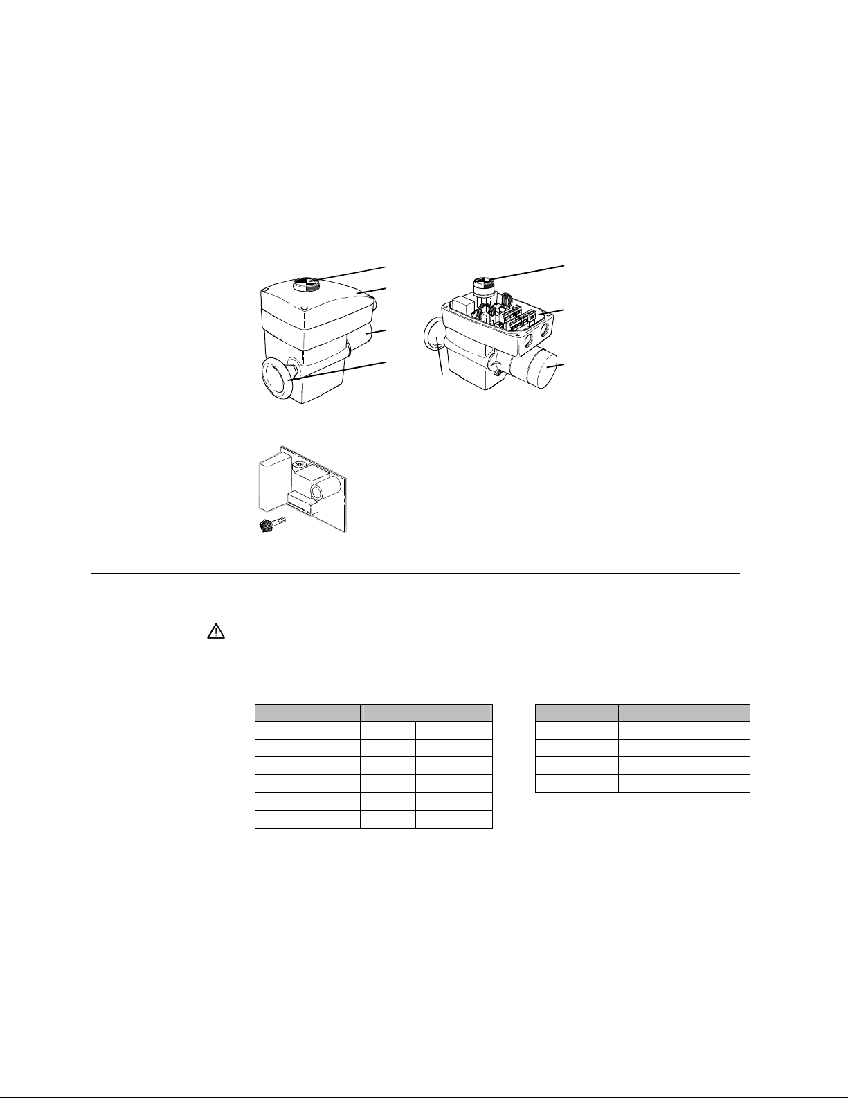
These electromotoric actuators require no maintenance. They have a reversible
asynchronous motor which drives the main shaft via spur gears and a self-locking worm
gear, which accommodates the rectangular shaft of the butterfly valve. The worm shaft
is fitted with a direct-acting manual adjuster.
The actuators are supplied with a 90° angle of rotation suitable for use with Siemens
butterfly valves. During automatic operation, rotation is limited by two built-in endswitches.
The direction of rotation of the actuator can be reversed (refer to «Commissioning»). To
prevent the temperature inside the housing from falling below the dewpoint temperature,
the actuators are supplied with a built-in heating element (AC 230 V, power
consumption 5 W).
Accessory for
SQL36E65
SQL36E110
SQL36E160
Engineering notes
Electrical installation
Mounting notes
1
4505Z37
4505Z38
2
3
4
1
1 Position indication
2 Terminal compartment
3 Motor
2
4 Manual adjuster
3
4
SEZ31.1
Auxiliary module
In the presence of a 3-position signal, the auxiliary module
4505Z10
pulses the actuator. The output shaft rotates by approximately 2°
with each pulse. The pulse-to-pause ratio is continuously
adjustable and can therefore be used to achieve longer running
times for an angle of rotation of 90° (refer to «Commissioning»).
The actuators must be electrically connected in accordance with local regulations and
with the connection diagrams.
Regulations and requirements to ensure the safety of people and property must
be observed at all times.
.
Overview of
Mounting Instructions
Type Mounting Instructions Type Mounting Instructions
SQL35.00/SQL85.00 M4290.4 74 319 0215 0 SQL36E… M4505.1 74 319 0440 0
ASK35… M4290.4 74 319 0215 0 ASC36 M4505.3 74 319 0442 0
ASK35 M4135.1 4 319 5556 0 ASZ36 M4505.2 74 319 0441 0
ASC9.4 G4506.5 4 319 5537 0 SEZ31.1 M4505.4 74 319 0443 0
ASC9.5 G4506.7 4 319 5557 0
ASZ7.4 G4506.6 4 319 5538 0
SQL35.00 / SQL85.00
These actuators must be used with the following mounting kit:
.
− ASK35.1 or ASK35.2 for VKF46… butterfly valves
− ASK35 for VKF41.150 and VKF41.200 butterfly valves
SQL36E...
These actuators are mounted directly on type VKF46... butterfly valves. The butterfly
valves have to be closed during installation.
In case of unsteady ambient temperatures connect the built-in heating element to avoid
condensation.
The valve and actuator can be assembled straightforwardly on site. There is no need
for special tools.
4/12
Building Technologies Electromotoric Actuators CA1N4505en
HVAC Products 26.10.2006
Page 5
4505Z40
4290Z02
4
5
0
5
Z
4
1
Orientation
... . . . . . . . . . . . . . . . . . . . . . . . . . . . . . . . . . . . . . . . . . . . .
SQL36E… SQL35…, SQL85…
90
90
.
Commissioning notes
Warning
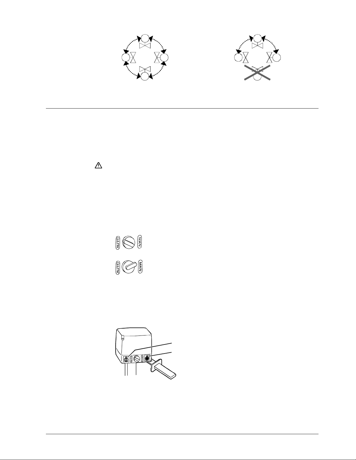
Operating mode
SQL35.00 / SQL85.00
4136Z01
4716Z16
Any Upright to horizontal
When commissioning the complete motorized valve consisting of actuator, mounting kit
and butterfly valve, always check the wiring and test the functions. This also applies to
any additional components fitted, e.g. auxiliary switch, potentiometer or auxiliary
module (variable positioning time).
VKF41… or VKF46... butterfly valves can only be commissioned with a SQL35.00 /
SQL85.00 or SQL36E… actuator or with an ASK46... manual adjuster fitted.
To avoid pressure shocks on the butterfly, the VKF46… must be driven to its fully open
position (either manually or via positioning signal Y1) prior to activating the pump(s).
The flow rate is adjusted either by driving the electric actuators as required, or by
operating the manual adjuster.
When using a SEZ31.1 auxiliary module set the desired positioning time:
SQL36E65: 30...180 s
SQL36E110: 60…360 s
SQL36E160: 120…720 s
«AUTO» = automatic operation
«MAN» = manual operation
SQL36E...
In the case of the SQL36E..., the manual adjuster is always engaged and cannot be
mechanically disconnected.
Direction of rotation
SQL35.00 / SQL85.00
The actuators are factory-set to rotate in clockwise direction for opening (as seen from
the cover).
Position indication
1
2
The adhesive labels supplied must be
applied during assembly.
1 Butterfly valve
in «OPEN» position
2 Butterfly valve
in «CLOSED» position
5/12
Building Technologies Electromotoric Actuators CA1N4505en
HVAC Products 26.10.2006
Page 6
SQL36E...
. . . . . . . . . . . . . . . . . . . . .
. . . .
Reversing the
direction of rotation
SQL35.00 / SQL85.00
SQL36E...
Setting the
angle of rotation
Control
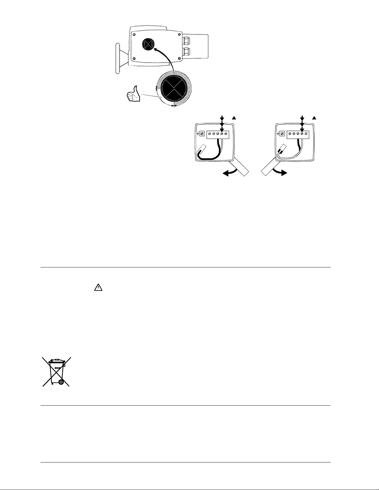
The direction of rotation of these types of
actuators for opening is counterclockwise.
ZU / CLOSED
ZU / CLOSED
90
4505Z03
The direction of rotation can
be reversed by
repositioning a connector
located under the cover.
The wiring for the OPEN
and CLOSE control signal
Y1
4505Z42
1211Y2Y1N
1
1
0
4505Z43
2
0
Y1
1211Y2Y1N
1
is not affected
Direction of rotation reversed
If the direction of rotation needs reversing, simply change the connections Y1/Y2.
The 0...90° angle of rotation for the end switches is factory-set and cannot be changed.
The potential-free auxiliary switches have adjustable switching points.
Every actuator must be driven by a dedicated controller (refer to «Connection
diagrams»).
.
Maintenance
Caution
Disposal
Warranty
The actuators and butterfly valves require no maintenance.
Before performing any service work on the valve or actuator:
• Switch off the pump and power supply
• Close the main shut-off valves in the pipework
• Release pressure in the pipes and allow them to cool down completely
If necessary, disconnect electrical connections from terminals.
The valve must be re-commissioned only with the manual adjuster or the actuator
correctly assembled.
The actuator contains electrical and electronic components and must not be disposed
of together with domestic waste.
Legislation may demand special handling of certain components, or it may be sensible
from an ecological point of view.
Current local legislation must be observed.
The technical data given for these applications is valid only in conjunction with the
Siemens butterfly valves as detailed under «Equipment combinations». The use of thirdparty valves other than those recommended by Siemens invalidates the warranty.
.
6/12
Building Technologies Electromotoric Actuators CA1N4505en
HVAC Products 26.10.2006
Page 7
Technical data
. . . . . . . . . . . . . . . . . . . . . . . . . . . . . . . . . . . . . .
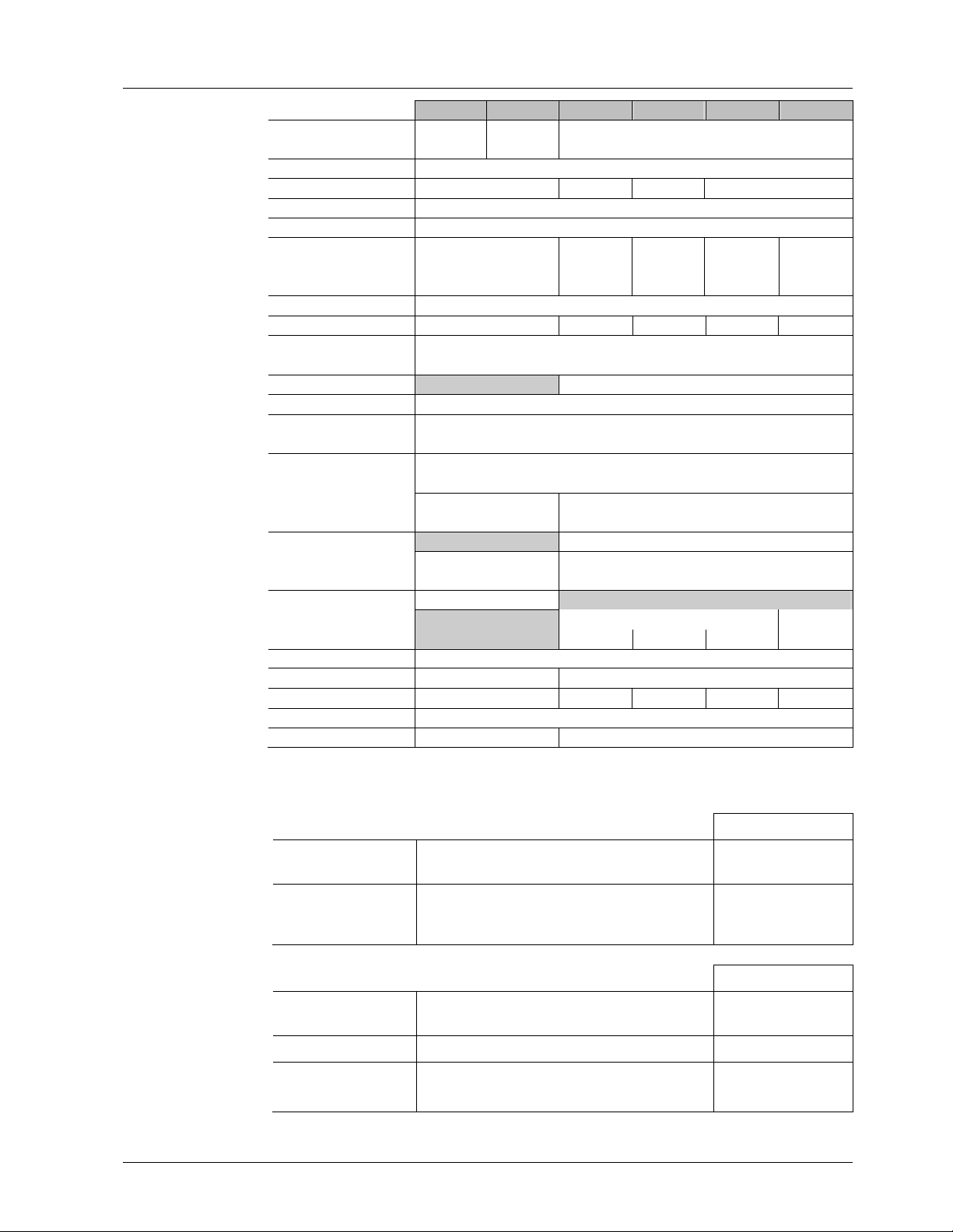
SQL35.00 SQL85.00 SQL36E50… SQL36E65 SQL36E110 SQL36E160
Power supply Operating voltage AC 230 V
±15 %
Frequency 50 / 60 Hz
Power consumption 1) 6.5 VA 35 VA 160 VA 235 VA
Control Positioning signal 3-position
Parallel operation parallel operation of several actuators not possible
Operating data Positioning time for 90°
at 50 Hz
at 60 Hz
Angle of rotation 90° ± 1° (factory setting)
Torque 1) 20 Nm 40 Nm 100 Nm 400 Nm 1200 Nm
End switch Switching capacity AC 250 V, 3 A resistive, 1.5 A inductive
Heating element AC 230 V, 5 W
Medium temperature Permissible temperature of medium in the assembled valve: 120°C
Standards Meets the requirements for
CE marking in
Electromagnetic
compatibility
Product standards for
automatic electrical controls
C-tick N474
Housing protection
standard
Protection class III or II to EN 60730
connection to actuator
Dimensions / weight Dimensions see «Dimensions»
Cable glands 4 x ∅ 20,5 mm (for M20)
Weight 1.4 kg 4.5 kg 7 kg 14 kg 25 kg
Materials Housing base, yoke die-cast aluminium
Cover plastic die-cast aluminium
1)
These values apply at nominal voltage, at an ambient temperature of 20 °C and at the specified nominal
running time
2)
Variable positioning time with SEZ31.1 auxiliary module (see below)
EN 60730-2-14 DIN EN 61010
IP 44 to IEC 60529 IP 67 to IEC 60529
AC 24 V
±20 %
125 s
105 s
Switching differential approx. 1°
EMC directive 89/336/EEC
Low-voltage directive 73/23/EEC
AC emissions: EN 61000-3-ff, EN 55014-1 and EN 55022
AC + DC immunity: EN 61000-4-ff
25 s
20 s
F04 / F05
AC 230 V
–5 / +10 %
2)
6 s
5 s
EN ISO 5211 32mm Flanges and shaft
F07 F10 F12 / F16
12 s 2)
10 s
2 x M20
24 s 2)
20 s
Accessories for SQL35.00 / 85.00 Weight
.
• Double auxiliary switch
ASC9.5 / ASC9.4
• Auxiliary switch with
potentiometer ASZ7.4
Switching capacity
Switching differential
Switching capacity
Switching differential
Change in resistance
AC 250 V, 10 A resistive, 3 A inductive
approx. 1°
AC 250 V, 10 A resistive, 3 A inductive
approx. 1°
0 ...1000 Ω corresponding to 0 ... 90 °
ASC9.4 85 g
ASC9.5 30 g
60 g
Accessories for SQL36E… Weight
• Double auxiliary switch
ASC36
Switching capacity
Switching differential
AC 250 V, 3 A resistive, 1.5 A inductive
approx. 1°
60 g
• Potentiometer ASZ36 Change in resistance 0...1000 Ω corresponding to 0...90° 50 g
• Auxiliary module
SEZ31.1
Building Technologies Electromotoric Actuators CA1N4505en
HVAC Products 26.10.2006
Positioning time for 90 °
at 50 Hz
SQL36E65: 30...180 s
SQL36E110: 60…360 s
SQL36E160: 120…720 s
60 g
7/12
Page 8
General
. . . . . .
. . . . . . . . . . . . . . . . . . . . . . . . . . . .
ambient conditions
Environmental conditions Class 3K5 Class 4K2 Class 2K3 Class 1K3
Temperature –15...+55 °C –20...+70 °C –30...+65 ° C –15...+55 ° C
Humidity
EN 60721-3-3 EN 60721-3-4 EN 60721-3-2 EN 60721-3-1
SQL35.00 / SQL85.00 SQL36E… SQL35.00 / SQL85.00 / SQL36E…
5...95 % r. h. 15...100 % r. h. < 95 % r. h. 0...95 % r. h.
Operation Transport Storage
Internal diagrams
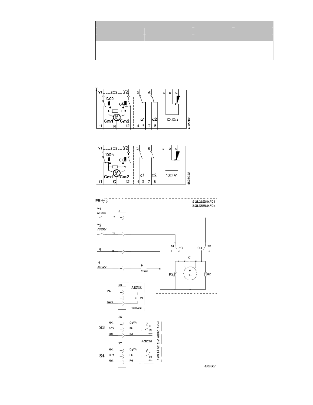
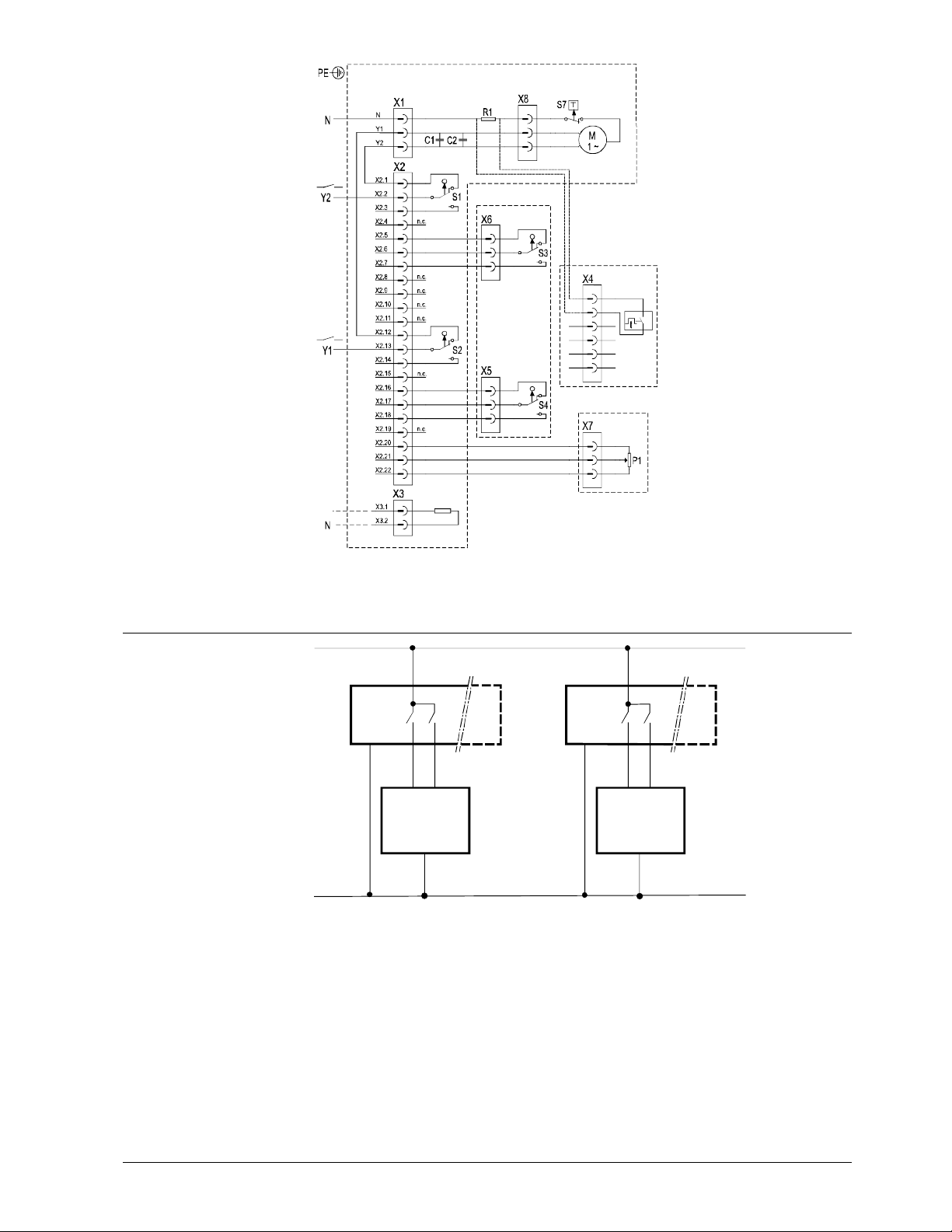
SQL35.00
Cm1 End switch
Cm2 End switch
c1 1 auxiliary switch ASC9.5
or
c1, c2 1 double auxiliary switch
ASC9.4
SQL85.00
or
c1, 1000 Ω 1 built-in unit ASZ7.4
(1 auxiliary switch and
1 potentiometer)
N Neutral conductor
G System potential
Y1 Control phase OPEN
Y2 Control phase CLOSED
11 Sequence Y1 at 90°
12 Sequence Y2 at 0°
.
SQL36E50F04
SQL36E50F05
S1 End switch CLOSED
S2 End switch OPEN
S3 Auxiliary switch
CLOSED (ASC36)
S4 Auxiliary switch
OPEN (ASC36)
H Heating element
P1 Potentiometer
(ASZ36)
Y1 Control phase OPEN
Y2 Control phase
CLOSED
N Neutral conductor
N.C. Normally Closed
N.O. Normally Open
COM Common conductor
.
8/12
Building Technologies Electromotoric Actuators CA1N4505en
HVAC Products 26.10.2006
Page 9
SQL36E65
. . . . . . . . . . . . . . . . . . . . . . . . .
SQL36E110
SQL36E160
AC 230 V
max. A C 250V 3A (1,5A)
ASC36
SQL36E65
SQL36E110
SQL36E160
SEZ31.1
S1 End switch CLOSED
S2 End switch OPEN
S3 Auxiliary switch CLOSED
(ASC36)
S4 Auxiliary switch OPEN
(ASC36)
S7 Thermal switch
(integrated)
H Heating element
P1 Potentiometer (ASZ36)
T1 Auxiliary module
(SEZ31.1)
Y1 Control phase OPEN
Y2 Control phase CLOSED
N Neutral conductor
.
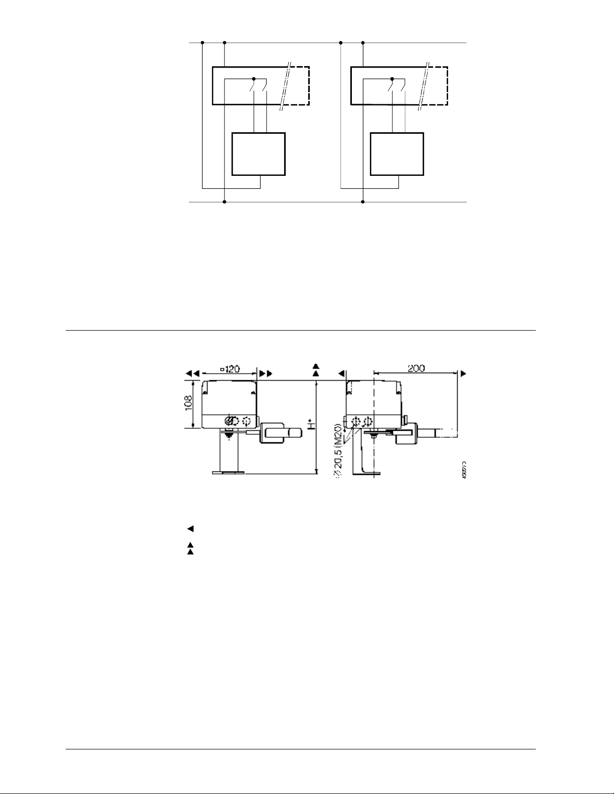
Connection diagrams
SQL35.00
SQL36E…
AC 230 V
AC 230 V
L
Q1
(N)
H
P = 5 W
(L)
Q2
(Y1) (Y2)
N1
Q1
(N)
(Y1) (Y2)
ASZ36
1000
4505G01
(L)
T1
Ω
4505A01
Q2
N2
AC 230 V
Y2Y1
N
Y1
N
Y2Y1
N
Y2
N1, N2 Controller
Y1, Y2 Actuator
L System potential AC 230 V
N System neutral
Q1, Q2 Controller contacts
9/12
Building Technologies Electromotoric Actuators CA1N4505en
HVAC Products 26.10.2006
Page 10
SQL85.00
SP
(G)
(G0)
Q1 Q2
(Y1)
(Y2)
N1
(G)
(G0)
Q1 Q2
(Y1)
(Y2)
4505A02
N2
Dimensions
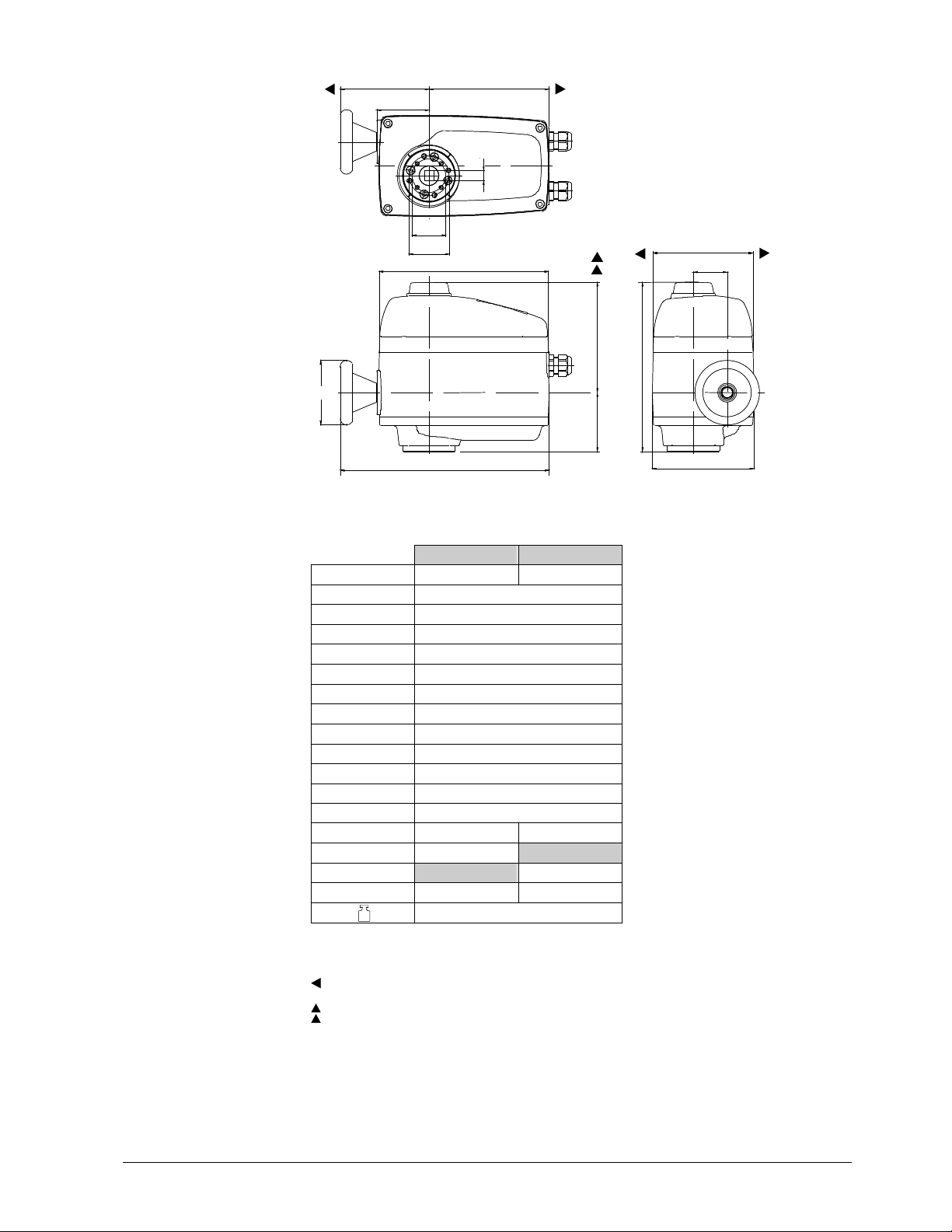
SQL35.00
SQL85.00
AC 24 V
SN
Y2Y1
G
Y1
N1, N2 Controller
Y1, Y2 Actuator
SP System potential AC 24 V
SN System neutral
Q1, Q2 Controller contacts
Dimensions in mm
Y2Y1
G
Y2
* Mounting height of actuator including ASK35... mounting kit = 168 mm
> 100 mm: Minimum clearance from wall or ceiling
> 200 mm: For mounting, connection, operation, service, etc.
10/12
Building Technologies Electromotoric Actuators CA1N4505en
HVAC Products 26.10.2006
Page 11
SQL36E50F04
. . . . . . . . . . . . . . . . . .
... . . . . . . . . . . . . . . . . . . . . . . .
SQL36E50F05
K J
K J
E
E
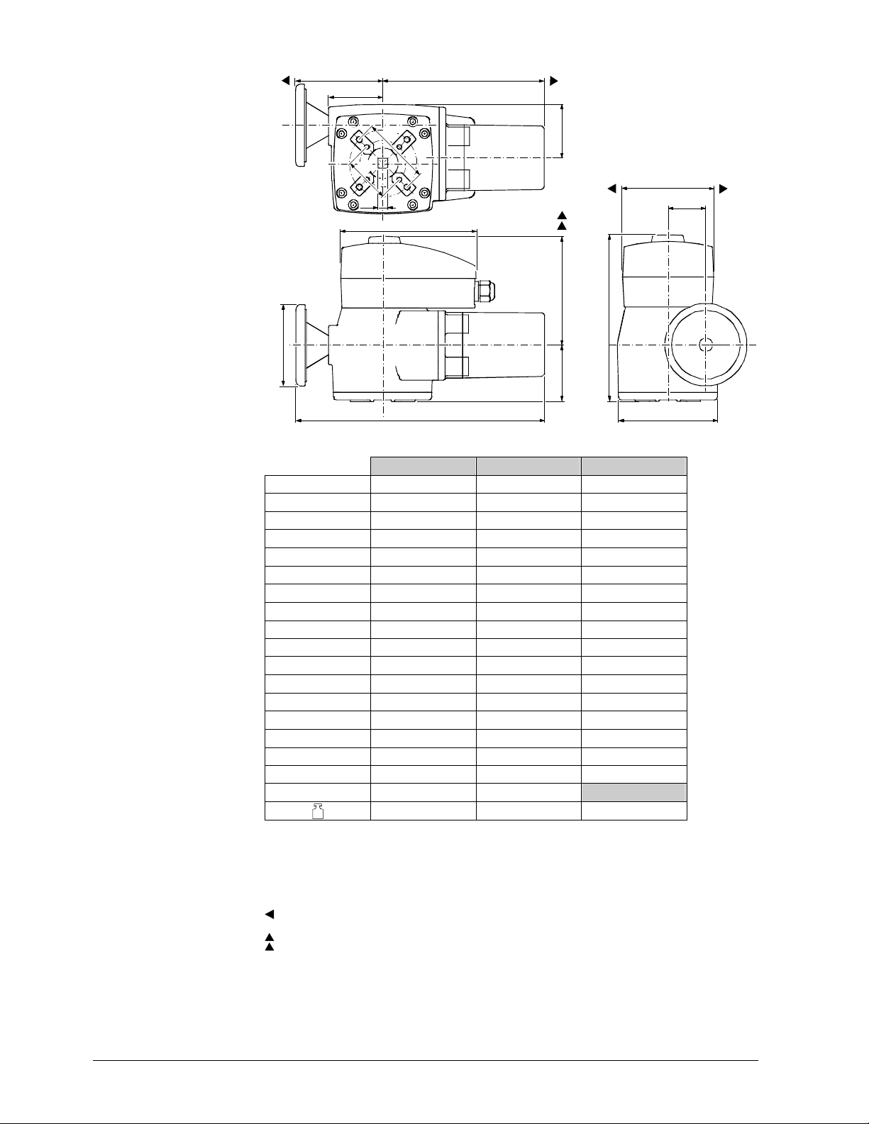
[mm]
.
XX
Z
Z
M
M
H
H
G
G
4505M03
Y
Y
A
A
C
C
D
D
B
B
L I
L I
SQL36E50F04 SQL36E50F05
DN 40…65 80…125
A 210
B 73
C 137
D 210
E 65
G Ø 80
H 42
I 126
J 149
K 110
L 259
M 124
X ¨ 11 ¨ 14
Y 42
Z 50
EN 5211 F04 F05
kg
> 100 mm: Minimum clearance from wall or ceiling
4.5 kg
> 200 mm: For mounting, connection, operation, service, etc.
11/12
Building Technologies Electromotoric Actuators CA1N4505en
HVAC Products 26.10.2006
Page 12
SQL36E65
. . . . . . . . . . . . . . . . . . . . . . . . . . . . . . . . . . . . . . . . . . .
Subject to alteration
SQL36E110
SQL36E160
K
J
[mm]
.
E
Y
F
Z
M
X
A
C
D
G
B
4505M02
L
SQL36E65 SQL36E110 SQL36E160
DN 150…200 250…400 (350) 450…600
A 208 208 208
B 78 88 112
C 157 169 170
D 235 257 282
E 65 81 110
F 65 87 126
G Ø 80 Ø 125 Ø 200
H 42 58 89
I 125 150 175
J 171 247 280
K 119 136 157
L 290 383 437
M 139 139 139
X ¨ 17 ¨ 22 ¨ 32
Y 70 102 165
Z 50 70 125
EN 5211 F07 F10
kg
1)
DN 350 / 400: VKF46.350TS, VKF46.400TS
2)
EN 5211 F12 / F16 flange connections for third-party actuators are available on request.
7 kg 14 kg 25 kg
> 100 mm: Minimum clearance from wall or ceiling
I
1)
2)
H
> 200 mm: For mounting, connection, operation, service, etc.
12/12
Building Technologies Electromotoric Actuators CA1N4505en
HVAC Products 26.10.2006
2003 – 2006 Siemens Switzerland Ltd
 Loading...