

Siemens SQD Series, SQD85.03U, SQD65U Installation Instructions Manual
SQD Series Valve Actuators
(For use with 1-1/2-inch to 2-inch Pressure Independent
Control Valves)
Product Description
The SQD Actuator requires a 24 Volt power supply
and a 0 to 10Vdc or floating signal to control the
Siemens 1-1/2 inch and 2-inch 599 Series Pressure
Independent Control Valves with 1/4-inch (6.5 mm)
stroke.
Warning/Caution Notations
WARNING:
CAUTION:
Personal injury/loss of life may
occur if you do not perform a
procedure as specified.
Equipment damage may occur
if you do not perform a
procedure as specified.
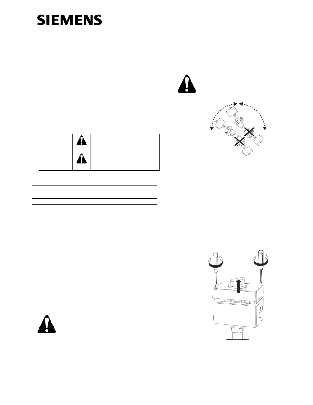
Figure 1. Acceptable Mounting Positions with Valve.
Installation Instructions
Document No. 129-553
December 22, 2011
WARNING:
Disconnect the controller power
before replacing the actuator.
90° 90°
EA1326R1
Product Number
Description Actuator
Code
SQD65U 0 to 10 Vdc control 235
SQD85.03U 3-position (floating) control 234
Required Tools
• 1-1/4-inch open end wrench
• #2 Phillips or flat-blade screwdriver
• Flat-blade calibration screwdriver (3 mm) for
wiring connections
• Wire cutter/stripper
Estimated Installation Time
• 15 minutes for wiring a factory-installed
actuator.
• 30 minutes for field replacement of actuator.
Prerequisites
WARNING:
NOTE: Vertical mounting is recommended.
Instructions
If you are mounting an actuator on a new valve, begin
with the instructions, Mounting an Actuator to a Valve.
Remove Actuator from Valve
1. Remove the actuator cover using either a #2
Phillips or a #2 flat blade screwdriver.
Figure 2.
See
1
1
1
2
If mounting the actuator to a valve
already in line, either close the shut-off
valves in the piping (upstream first,
then downstream) or switch off the
pump to allow the differential pressure
in the valve to drop.
Item Number: 129-553, Rev. AA Page 1 of 4
2. Disconnect and identify the wires. Place the cover
back on the actuator.
EA1331R1
M30 x 1.5
Figure 2.
Document No: 129-553
Installation Instructions
December 22, 2011
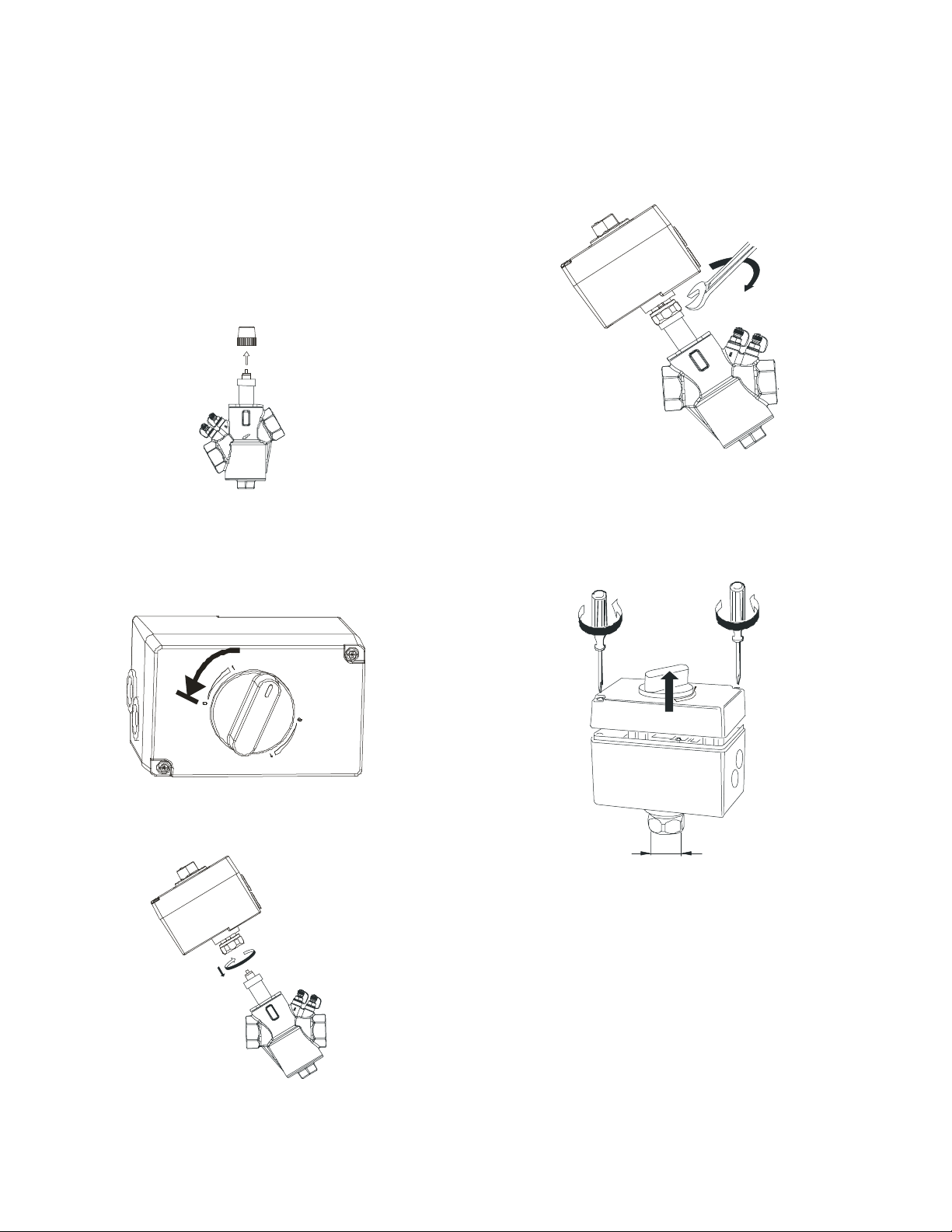
Remove Actuator from Valve, Continued
3. Use a 1-1/4-inch open end wrench to loosen the
coupling piece.
4. Remove the actuator from the valve.
Mounting an Actuator to a Valve
1. If you are attaching the actuator to a new valve,
remove the protective plastic cap from the valve
stem. See
Figure 3.
4. Use a 1-1/4-inch open-end wrench to tighten the
coupling piece to a maximum of 22 ft-lbs. See
Figure 6.
VPI45.., VPI45..Q
EA1327R1
Figure 3.
2. Turn the manual-positioning knob
counterclockwise to “0”. See
EA1328R1
Figure 4.
Figure 4.
3. Place the actuator on the valve. See Figure 5.
EA1330R1
Figure 6.
5. Use either a Phillips head screwdriver or a flatblade screwdriver to remove the actuator cover for
access to the terminal block, selector plug, and
jumper wire. See
Figure 7.
1
1
1
2
EA1331R1
M30 x 1.5
Figure 7.
6. Attach wires, set the selector plug and if
2
1
necessary, cut the R–M jumper. See Wiring.
7. Place the cover on the actuator. The positioning
knob must be at “0” to fit into the shaft. If the cover
does not fit, turn it 180 degrees.
EA1329R1
Figure 5.
Page 2 of 4 Siemens Industry, Inc.
 Loading...