

Siemens SKP Series, SKP70.110U17, SKP70.111U17, SKP70.192U17, SKP70.191U17 Technical Instructions
...Page 1
SKP Series
SKP70…U.. Air/Gas Ratio Controlling Actuators
With Safety Shutoff Function—
For Use With Gas Valves VG…
Te
Tecccchhhhnnnniiiiccccaaaal I
TeTe
l Innnnssssttttrrrruuuuccccttttiiiion
l Il I
onssss
onon
Document No. 155-516P25
SKP70…U..
Rev. 2, December, 1998
DDDDes
esccccrrrriiiippppttttiiiioooonnnn
eses
SKP70… pressure regulating electro-hydraulic actuators are used in combination with
VG… series gas valves to provide slow opening fast closing shutoff and air/gas ratio
control for industrial and commercial burner applications.
The SKP70… controls the burner manifold gas pressure as a function of the
combustion air pressure without the need for an additional constant gas pressure
regulator.
Since three functions, safety shutoff, constant pressure regulation and air/gas ratio
control can be performed by a single valve, fewer components and fittings are required
to assemble a gas train reducing both the size and the weight of the gas train
significantly. The total pressure drop across the gas train arrangement is reduced,
allowing for the use of smaller diameter gas trains in most applications.
The modular design allows the SKP70… to be used in combination with all VG… series
gas valves from ½-inch to 5-inch in size. The actuator is easily mounted on the square
flange of any VG… valve by means of four bolts contained in the terminal box of the
actuator. No gaskets or seals are required when mounting the actuator. The valve
position is shown by a visible position indicator displaying the entire stroke range of the
actuator.
Siemens Building Technologies, Inc.
Landis Division
Page 2

Technical Instructions
Document No. 155-516P25
Rev. 2, December, 1998
FFFFeeeeaaaattttur
ures
es
urur
eses
AAAApp
ppli
liccccaaaattttiiiioooonnnn
pppp
lili
UL listed, FM approved, CGA and AGA certified, IRI approvable, ISO 9001 certified;
x
European, Australian and Japanese approved versions available.
Safety shutoff function, pressure regulating function and air/gas ratio control in one
x
compact unit.
Simplifies commissioning and reduces startup time.
x
Maintains air/gas ratio when the air flow is disrupted.
x
Automatic compensation for combustion chamber back pressure fluctuations.
x
No mechanical wear or play that causes drifting.
x
Compensation for air temperature fluctuations.
x
Visual stroke position indicator.
x
Can be mounted in any location.
x
Optional auxiliary switches available.
x
Excellent tracking characteristics
x
SKP70… series actuators can be combined with ½-inch to 5-inch VG… series gas valve
bodies. VG… series gas valves are ordered as separate items (
Instruction No. 155-512P25).
VG…U.. Technical
See
PPPPrrrroooodu
ducccct
dudu
t NNNNuuuummmmbbbbeeeerrrrssss
t t
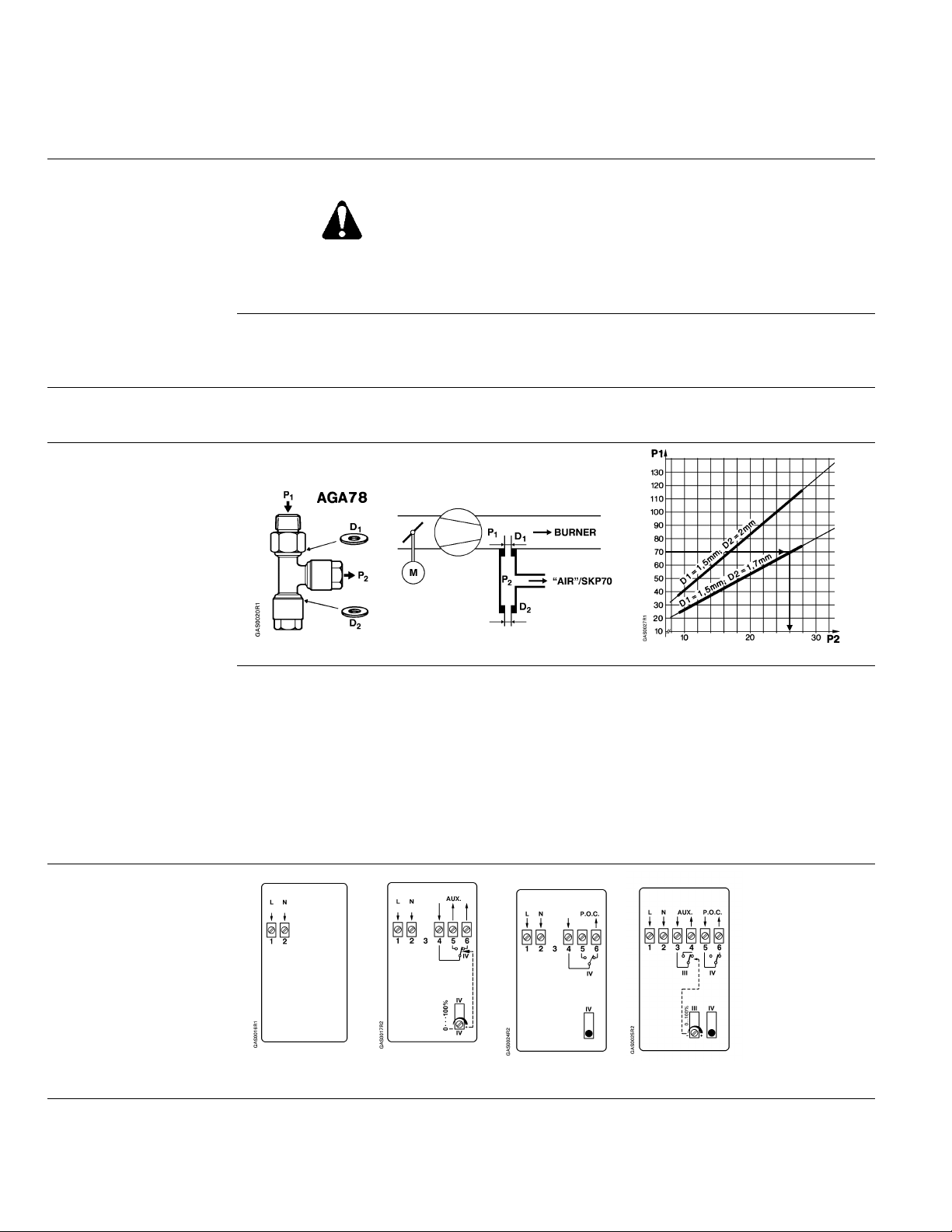
If the combustion air pressure exceeds the permissible value of 12” or 20” w.c. (
Specifications), the pressure must be reduced by means of a pressure reducing Tfitting (
A motorized pressure reducing control (SQN37… ) can also be installed in the air
impulse line to continuously optimize combustion when used in conjunction with an
oxygen trim system.
Figure 4, AGA78).
See
TTTTaaaabbbblllle
e 1111.
. PPPPrrrroooodddduuuucccct
e e
. .
OOOOrrrrddddeeeer
r NNNNuuuummmmbbbbeeeerrrrO
r r
SKP70.110U17 110-120 Vac No —
SKP70.111U17 110-120 Vac Auxiliary SPDT
SKP70.191U17 110-120 Vac Proof of Closure SPST
SKP70.192U17 110-120 Vac
SKP70.110U27 220-240 Vac No —
SKP70.111U27 220-240 Vac Auxiliary SPDT
SKP70.192U27 220-240 Vac
AGA78
OOOppppeeeerrrraaaattttiii
ing
ng
ngng
VVVVoooollllttttaaaage
ge
gege
Air pressure reducing T-fitting
t NNNNuuuummmmbbbbeeeerrrrssss
t t
PPPPrrrroo
oof
f oooof
f CCCClllloooossssuuuurrrreeee
oooo
f f
f f
&
& AAAAuuuuxxxxiiiilllliiiiaaaarrrry
& &
Proof of Closure
Proof of Closure
y SSSSwwwwiiiittttcccchhhh
y y
& Auxiliary
& Auxiliary
TTTTyyyyppppe o
SSSSwwwwiiiittttcccchhhh
SPST
SPST
SPST
SPST
e offff
e oe o
See
IIIInnnnssssttttaaaall
PPPPaaaage
ge 2222 oooof
ge ge
llaaaattttiiiioooon
n CCCCoooonnnnvvvveeeennnnttttiiiioooonnnn
llll
n n
WARNING:
f 9999 Siemens Building Technologies, Inc.
f f
Personal injury/loss of life may occur if a
procedure is not performed as specified.
Landis Division
Page 3

SKP70…U.. Air/Gas Ratio Controlling Actuators Technical Instructions
155-516P25
Rev. 2, December, 1998
SSSSppppeeeecccciiiiffffiiiiccccaaaattttiiiioooonnnnssss
Agency approvals
Power supply
Operating environment
Physical characteristics
Connections
Operating characteristics
Control signal
Operation/installation
Auxiliary features
As safety shut-off valve UL/429, FM/7400, CGA/3.9,
AGA/Z 21.21 in combination with
VG…U.. series gas valves
UL recognized when used with other valves.
Operating voltage 110 to 120 Vac + 10%-15%
220 to 240 Vac + 10%-15%
Operating frequency 50 to 60 Hz + 6%
Power consumption 20 VA
Duty cycle 100%
o
Ambient operating temperature 15
to 140oF (-10o to 60o C)
Mounting position Optional, with diaphragms in vertical
position but not upside down
Maximum temperature of air and flue
gas at the control connections 140
o
F (60oC)
Maximum inlet gas pressure Same as VG… valve
Weight 5.5 lb (2.5 kg)
Enclosure NEMA 1, 2, 5 and 12 for indoor use
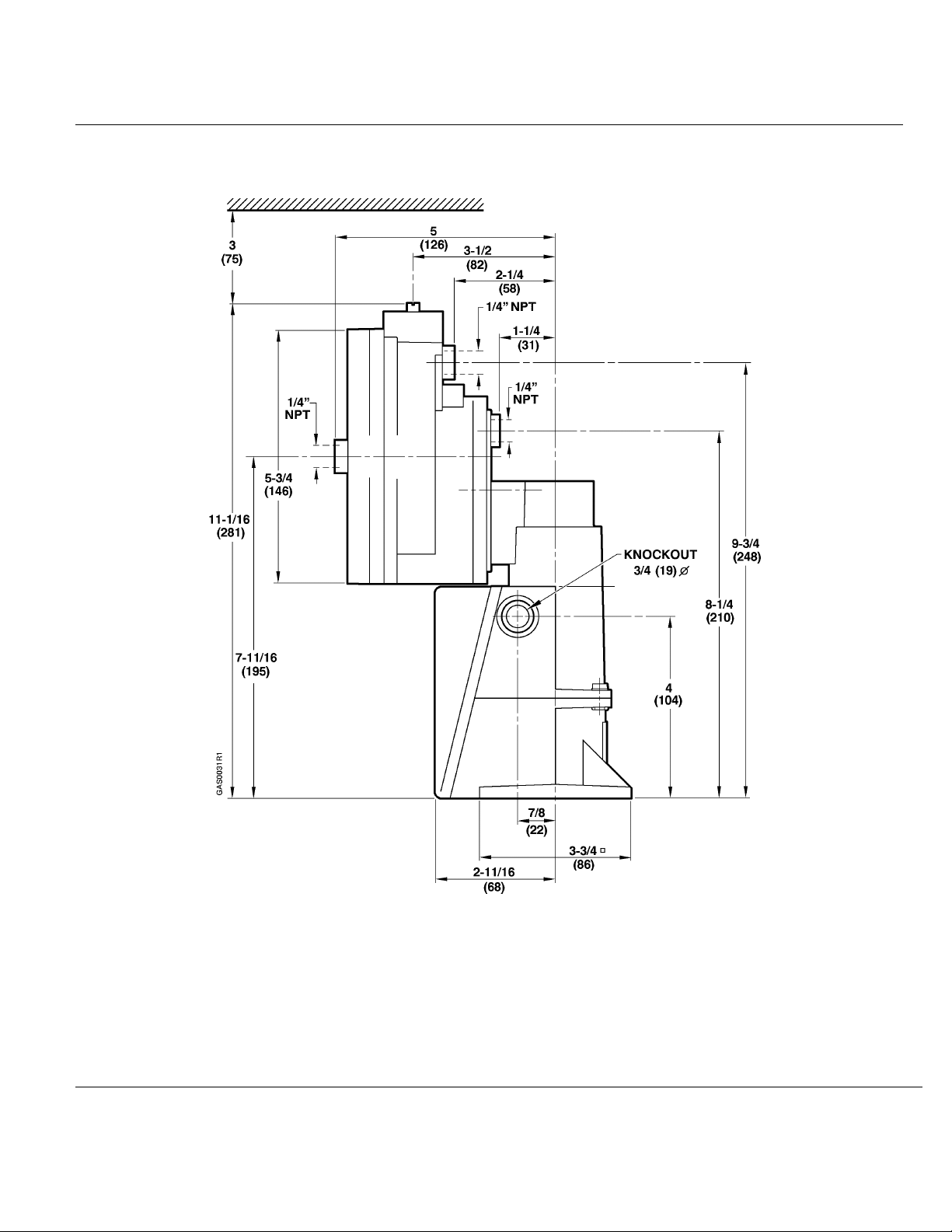
Dimensions
Specification for valves
Figure 6
See
gas valve Technical Instruction
See
No. 155-512P25
Conduit connection ½-inch NPSM adapter
Gas/air/combustion chamber pressure
connections ¼” NPT
Output force 100 lb (450 N)
Maximum stroke 0.7” (18 mm)
Opening time for maximum stroke 12 s
Closing time < 0.8 s
Reference input signal Combustion air pressure
Control characteristic integral action
Setting range of gas to air pressure ratio 0.4:1 to 9:1
Permissible pressures
during operation for accurate control Min. air presssure: 0.2” w.c.
Max. air pressure: with Pg/Pa <2; 20” w.c.
Max. air pressure: with Pg/Pa >2; 12” w.c.
with higher air pressures use AGA78
Min. downstream gas pressure: 0.4” w.c.
Max. downstream gas pressure: 40” w.c.
Minimum time required for high to low
fire load changes Approx. 5 s
Permissible leakage test pressure 20 psi
Permissible leakage test vacuum 3 psi
Minimum diameter of impulse pipes ¼” inside diameter (
Installation)
See
Minimum distance between gas
impulse pipe connection and gas
valve outlet 5 x pipe diameter
Capacity of auxiliary switch 6 (3) A, 250 Vac
Setting range of auxiliary switch Full stroke
Siemens Building Technologies, Inc PPPPaaaage
Landis Division
ge 3333 oooof
ge ge
f 9999
f f
Page 4

Technical Instructions
Document No. 155-516P25
Rev. 2, December, 1998
OOOOppppeeeerrrraaaattttiiiioooonnnn
((((
SSSSee
ee
Fi
Figgggur
ure
FiFi
urur
e 1111))))
e e
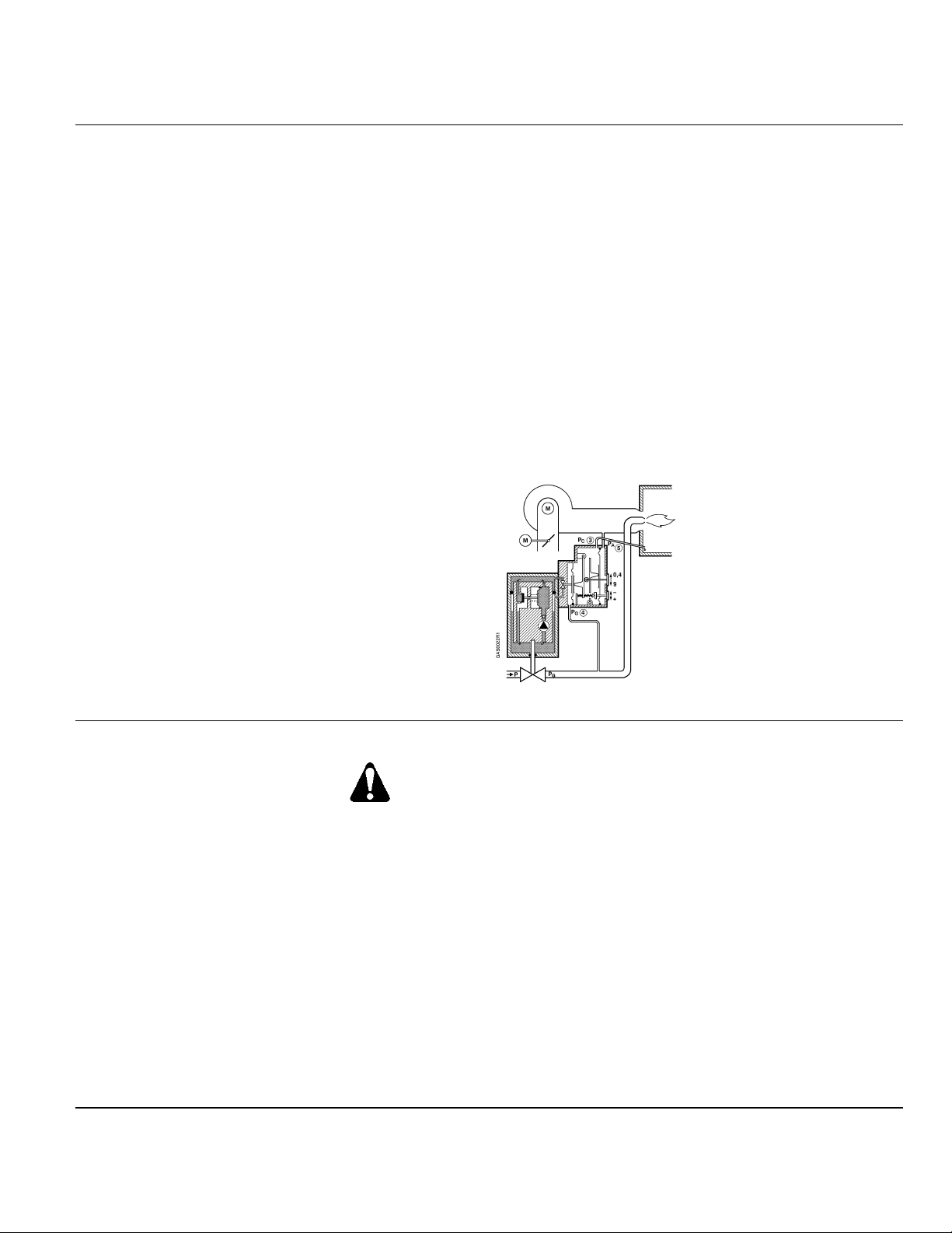
containing an electric oscillating pump and a hydraulic relief system. When power is
supplied to the actuator, the pump located at the base of the piston moves oil from the
reservoir (through an orifice) into the pressure chamber. The oil flow from the pump
through the orifice creates a pressure difference moving the diaphragm and the
attached spring loaded plug to the left, closing the return flow path from the pressure
chamber to the reservoir. This action causes the piston to move downward in the
cylinder opening the gas valve. When power to the pump is interrupted, the pressure
difference across the orifice instantly reduces to zero. The plug is immediately pushed
to the right allowing the oil to flow back from the pressure chamber into the reservoir,
closing the valve in less than 0.8 seconds. This unique hydraulic relief system provides
definite closure of the associated gas valve guaranteeing fail safe operation.
A visible disk fitted to the pump shaft indicates the entire stroke range of the actuator.
The disk also operates optional potential free switches via a set of levers. The
switching position of the auxiliary switch is adjustable over the entire stroke. The proof
of closure switch is non-adjustable.
eeee
Safety Shutoff Function The electro-hydraulic actuator consists of a cylinder filled with oil and a piston
Regulating Function During the burner pre-purge period, when the gas valve is closed, only the air pressure
acts on the regulator causing the air diaphragm to move to the left and close the
regulating hydraulic bypass valve. When the actuator is powered the gas valve begins to
open. The downstream differential gas pressure immediately begins to increase until the
downstream gas pressure is in balance with the air pressure (in accordance with the
pressure ratio adjusted on the regulator). The bypass valve is now partially open so that
the oil flow supplied by the pump is identical to the return flow. Unlike conventional
direct acting regulators the SKP70… servo operated regulating system displays virtually
zero droop (offset) across the turndown range.
If, for example, heat demand increases, the air damper would open further increasing
the air pressure. The air diaphragm would move to the left, causing the bypass valve to
close and the gas valve to open further. The opening of the gas valve increases the
downstream gas pressure moving the gas diaphragm to the right until balance is
restored and the flow supplied by the pump is once again identical to the return flow
through the regulator bypass.
The gas to air pressure ratio is adjustable from 0.4:1 to 9:1. The setting is visible through
a window in the regulator. Once set, the gas to air pressure ratio remains constant over
the entire output range. The gas to air flow ratio will remain constant (provided that the
cross sections of the air and gas orifices in the burner head are fixed). The SKP70… is
not recommended for use with burners incorporating a sliding/continuously adjustable
head arrangement.
Many burner designs, because of reduced mixing energy at the low fire level, require
somewhat more low fire air in order to maintain optimum combustion parameters. To
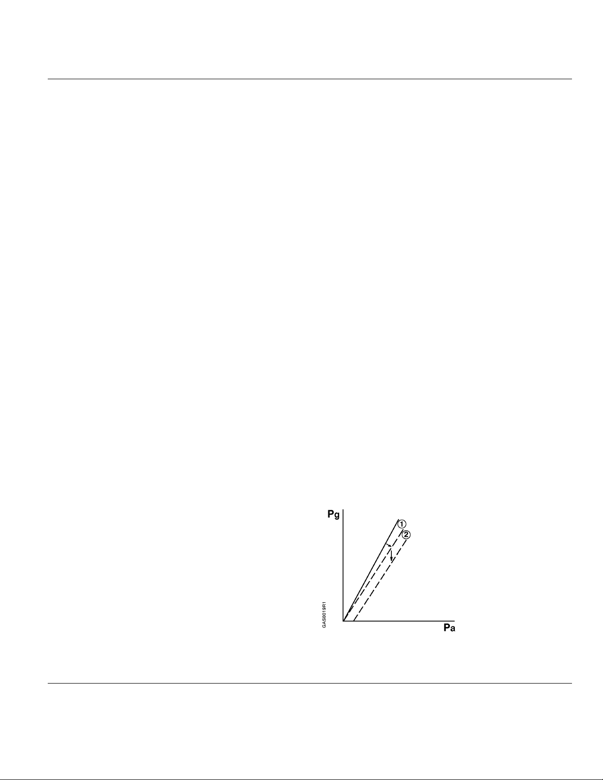
accommodate this requirement the SKP70… incorporates a bias spring parallel
displacement adjustment which allows the characteristic of the regulator to be displaced
either towards excess air or reduced air.
PPPPaaaage
ge 4444 oooof
ge ge
f 9999 Siemens Building Technologies, Inc.
f f
Landis Division
Page 5
SKP70…U.. Air/Gas Ratio Controlling Actuators Technical Instructions
155-516P25
Rev. 2, December, 1998
OOOOppppeeeerrrraaaattttiiiioooonnnn,
, ccccoooonnnntttt’’’’dddd....
, ,
The SKP70… also has the ability to compensate for pressure disturbances in the
combustion chamber. Typically in installations where the resistance in the combustion
chamber and the stack is constant, the combustion chamber pressure changes in
proportion to the gas and air pressures as the burner output is varied. Under these
circumstances it is generally not necessary to compensate for the combustion chamber
pressure. If however, the combustion chamber pressure does not change in proportion
to the gas or air pressure (as is the case with flue gas dampers or flue gas fans),
connection of the combustion chamber pressure to the regulator is necessary. This
compensation circuit should also be employed when pressure shocks or vibrations
disrupts the burner startup phase.
The SKP70… regulator gas diaphragm incorporates an additional safety diaphragm. In
the event of a gas diaphragm rupture, the reinforced safety diaphragm serves to prevent
excessive leakage of gas. With the SKP70…, leakage due to diaphragm rupture stops
when the burner shuts off and the valve is closed. (Conventional regulators continue to
leak and therefore have to be vented to the outdoors.)
NNNNooootttteeee:::: To avoid oscillation, do not oversize the VG… valve. (
Technical Instruction No.
See
155-512P25.)
FFFFiiiigggguuuurrrre
e 1111.
IIIInnnnssssttttaaaall
llaaaattttiiiioooonnnn
llll
. SSSSKKKKPPPP77770000…………UUUU.....
e e
. .
. OOOOppppeeeerrrraaaattttiiiioooonnnn....
. .
WWWWAAAARRRRNNNNIIIINNNNGGGG::::
All installation must be carried out by qualified
personnel only.
The SKP70… actuator is directly coupled to the VG… series valve body by four bolts
found in the terminal box of the actuator. The square mounting flange can be rotated in
steps of 90
o
providing four different mounting positions. The actuator can be mounted in
any position with the diaphragm vertically oriented but cannot be mounted in the upside
down position. The actuator can be mounted or replaced while the gas valve is installed
and under pressure. The actuator should be mounted so that the stroke position
indicator is clearly visible.
The SKP70… actuator packing contains an electrical conduit adapter to match with
½”-14 NPSM conduit. If the actuator is equipped with an auxiliary or proof of closure
switch, two such adapters are included.
NNNNooootttteeee:::: Wiring must conform with local electrical codes.
Siemens Building Technologies, Inc PPPPaaaage
Landis Division
ge 5555 oooof
ge ge
f 9999
f f
Page 6
Technical Instructions
Document No. 155-516P25
Rev. 2, December, 1998
IIIInnnnssssttttaaaall
llaaaattttiiiioooonnnn,
llll
, ccccoooonnnntttt’’’’dddd....
, ,
All pressure connection pipes must be at least ¼-inch inside diameter. For air to gas
pressure ratios over three, the air and combustion pressure connection pipes must be at
least 3/8” inside diameter. The pressure pick up conections must be flush with the inner
wall of the pipe or housing in order to sense turbulence free pressures. The gas pressure
pick up should be located at least five pipe diameters downstream of the valve. DDDDo no
uuuusssse
e tttthe
he ttttaaaapppps
s on
on tttthe
e e
he he
mmmmaaaay s
y sho
how
w ttttuuuurrrrbbbbuuuulllleeeennnncccceeee.... The pressure connection pipes should be as short as possible to
y sy s
hoho
w w
allow the regulator to react to sudden changes. The connection pipe for the combustion
chamber pressure must be installed so that condensing flue gases cannot enter into the
regulator but run back into the combustion chamber. If necessary, a water separator
must be installed.
s s
on on
he vvvvaaaallllvvvve
he he
e bbbbooooddddy
y ffffoooor
r ggggaaaas
s cccconn
e e
y y
WWWWAAAARRRRNNNNIIIINNNNGGGG::::
If minimum gas pressure detection is required, the
pressure switch must be mounted upstream of the
regulating gas valve to ensure sufficient gas pressure
before starting the burner. If maximum gas pressure
detection is required the pressure switch must be
mounted downstream of the valve.
WWWWAAAARRRRNNNNIIIINNNNGGGG::::
Air proving safety devices normally required to
guarantee minimum air flow must also be provided
when using the SKP70…
r r
onneeeeccccttttiiiion
s s
onnonn
on tttto
o tttthe
on on
o o
he rrrregu
egullllaaaattttoooor
he he
eguegu
r ssssiiiinnnncccce
e tttthe
r r
e e
hesssse
hehe
e ppppllllac
aceeeessss
e e
acac
o notttt
o noo no
WWWWAAAARRRRNNNNIIIINNNNGGGG::::
In installations with negative air pressure the SKP70…
does not work unless a higher negative chamber
pressure is connected to the regulator.
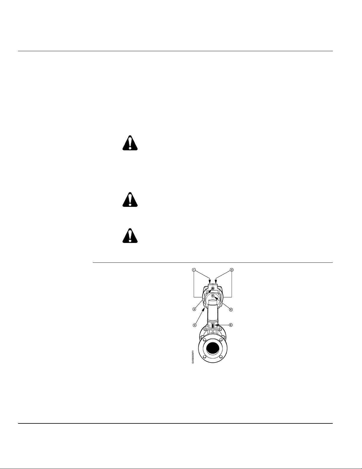
Adjustment and indication of the gas to air ratio
•
Adjustment and indication of the bias
•
Connection for the combustion chamber pressure sensing line
‘
Connection for the gas pressure sensing line
’
Connection for the air pressure sensing line
“
Stroke indication
”
FFFFiiiigggguuuurrrre
e 2222.
. CCCCoooonn
e e
nneeeeccccttttiiiioooonnnns
. .
nnnn
s aaaannnnd
d AAAAddddjjjjuuuussssttttmmmmeeeennnnttttssss....
s s
d d
PPPPaaaage
ge 6666 oooof
ge ge
f 9999 Siemens Building Technologies, Inc.
f f
Landis Division
Page 7
SKP70…U.. Air/Gas Ratio Controlling Actuators Technical Instructions
155-516P25
Rev. 2, December, 1998
St
Staaaarrrrt
t up
up
StSt
t t
upup
The pressure ratio and bias adjustment screws are located on top of the regulator under
a sealable cover plate. The actual settings can be seen through windows on each side of
Regulator (
Figures 2
See
the regulator.
and 3)
NNNNooootttteeee:::: The burner capacity is controlled by the position of the air damper. The
combustion quality (air/gas ratio) is controlled by the settings on the regulator (the
+ and – indications relate to the change in gas flow). Adjustment in clockwise
direction decreases the gas flow.
1. Set the gas to air ratio to the desired value using the adjusting screw • (coarse
setting).
2. Start the burner and run it at approximately 90% of full capacity.
3. Measure CO
until optimum values are obtained (fine setting).
•
4. Return to low fire and measure the CO
or O2 content in the flue gases and correct the ratio by adjusting screw
2
or O2 content in the flue gases. If necessary,
2
correct the setting by adjusting screw • until optimum values are obtained.
5. Limit the damper position for low fire operation. If considerable parallel displacement
was necessary to achieve optimum combustion, repeat the procedure from step 3.
6. Run the burner to the required high fire position and limit the air damper position.
7. Check the flue gas values at several intermediate output levels. If corrections are
necessary, note the following:
Adjust the pressure ratio screw • at high fire operation only.
x
Adjust the bias screw • at low fire operation only.
x
If the air pressure exceeds the maximum value of 12” or 20” w.c. (
See
Specifications), the pressure must be reduced by means of a pressure reducing
T-fitting (AGA78).
FFFFiiiigggguuuurrrre
e 3333.
. AAAAddddjjjjuuuussssttttmmmmeeeennnnttttssss....
e e
. .
Siemens Building Technologies, Inc PPPPaaaage
Landis Division
ge 7777 oooof
ge ge
f 9999
f f
Page 8
Technical Instructions
Document No. 155-516P25
Rev. 2, December, 1998
St
Staaaarrrrt
t up
up,
t t
upup
, ccccoooonnnntttt’’’’dddd....
, ,
StSt
WWWWAAAARRRRNNNNIIIINNNNGGGG::::
When firing at maximum burner capacity,
ensure that the SKP70… /VG… is no
fully open position. If this is the case, either the
gas valve is sized too small or the gas supply
pressure is too low.
notttt in the
nono
Auxiliary and Proof of
Closure Switch (
Terminal Designations)
SSSSeeeerrrrvi
vicccceeee
vivi
PPPPrrrress
essur
ure
essess
urur
TTTT----Fi
Fitt
ttiiiinnnng
g AAAAGGGGAAAA78
FiFi
tttt
g g
Function The air is blown out continuously into the atmosphere through the restrictor D
See
e RRRReeeedu
ducccciiiing
e e
dudu
78
7878
Adjust the auxiliary switch (if provided) according to the wiring diagram located on the
inside of the terminal box cover. The proof of closure switch is non-adjustable.
There are no serviceable parts on the SKP70… series actuators. If inoperative, replace the
actuator. Tag wires before servicing.
ng
ngng
FFFFiiiigggguuuurrrre
e 4444.
. AAAAGGGGAAAA77778
e e
. .
undergoes a drop in pressure across the restrictor D
diagram (Figure 5).
Example: Given p
8 OOOOppppeeeerrrraaaattttiiiioooonnnn....F
8 8
= 70 mbar, D1 = 1.5 mm, D2 = 1.7 mm
1
Find: Pressure signal P
= 26 mbar
P
2
for SKP70…
2
re
e 5555.
FFFiiiigggguuuurrr
. The relationships are shown in the
1
. AAAAGGGGAAAA77778
e e
. .
8 AAAAddddjjjjuuuussssttttmmmmeeeennnnttttssss
8 8
. The air
2
.
TTTTeeeerrrrmmmmiiiinnnnaaaallll
DDDDes
esiiiign
gnaaaattttiiiioooonnnnssss
eses
gngn
PPPPaaaage
ge 8888 oooof
f 9999 Siemens Building Technologies, Inc.
ge ge
f f
Reducing T-fitting AGA78 is supplied ready for mounting, complete with D
D
= 1.7 mm. An additional restrictor D2 with a diameter of 2 mm is included in the
2
packing.
SK
SKPPPP77770000....111110
SKSK
10UUUU..
1010
.. SK
SKPPPP77770000....111111
....
SKSK
11UUUU..
1111
.. SK
SKPPPP77770000....111191
....
SKSK
91UUUU..
9191
.. SK
SKPPPP77770000....111192
....
SKSK
92UUUU....
9292
= 1.5 mm and
1
.
Landis Division
Page 9
SKP70…U.. Air/Gas Ratio Controlling Actuators Technical Instruction
155-516P25
Rev. 2, December,1998
DDDDiiiimmmmeeeennnnssssiiiioooonnnnssss
FFFFiiiigggguuuurrrre
e 6666.
. SSSSKKKKPPPP77770000…………UUUU.....
e e
. .
. DDDDiiiimmmmeeeennnnssssiiiioooonnnnssss....
. .
(Dimensions given in inches; millimeters shown in parentheses.)
Information in this publication is based on current specifications. The company reserves the right to make changes in specifications and models as
design improvements are introduced. © 1998 Siemens Building Technologies.
SSSSiiiieeeemmmmen
ens
s BBBBuuuuil
ilddddiiiing
ng TTTTeeeecccchn
hnoooollllog
ogiiiieeeessss,
enen
s s
ilil
ng ng
Landis Division
1000 Deerfield Parkway
Buffalo Grove, IL 60089-4513
USA
hnhn
ogog
, IIIInnnncccc....
, ,
Document No. 155-516P25
Printed in the U.S.A.
PPPPaaaage
ge
9999 oooof
f 9999
ge ge
f f
 Loading...