

Siemens Sivacon S8 Planning Information
Totally Integrated Power
SIVACON S8
Technical Planning Information · 10/2015
www.siemens.com/sivacon-s8

Qualifiziertes Personal
Qualified Personnel
The product/system described in this documentation may be operated only by personnel qualified for the specific
task in accordance with the relevant documentation, in particular its warning notices and safety instructions.
Qualified personnel are those who, based on their training and experience, are capable of identifying risks and
avoiding potential hazards when working with these products/systems.
Proper use of Siemens products
Note the following:
WARNING, death or severe personal injury may result if proper
precautions are not taken.
Siemens products may only be used for the applications described in the catalog and in the relevant technical
documentation. If products and components from other manufacturers are used, these must be recommended
or approved by Siemens. Proper transport, storage, installation, assembly, commissioning, operation and
maintenance are required to ensure that the products operate safely and without any problems. The permissible
ambient conditions must be complied with. The information in the relevant documentation must be observed.
Disclaimer of Liability
We have reviewed the contents of this publication to ensure consistency with the hardware and software
described. Since variance cannot be precluded entirely, we cannot guarantee full consistency. However, the
information in this publication is reviewed regularly and any necessary corrections are included in subsequent
editions.

SIVACON S8
Technical Planning Information
System-based power distribution
1
1
SIVACON S8 – System overview
Circuit-breaker design
Universal mounting design
In-line design, plug-in
Cubicles in fixed-mounted design
Reactive power compensation
2
3
4
5
6
7
Further planning notes
Conforming to standards and design-verified
Technical annex
Glossary and rated parameters
SIVACON S8 Planning Principles –
8
9
10
11
1

Content
1 System-based power distribution 4
2 SIVACON S8 – System overview 8
2.1 System configuration and cubicle design 10
2.2 Corner cubicle 15
2.3 Main busbar, horizontal 16
2.4 Connection points for earthing and
short-circuit devices 17
2.5 Overview of mounting designs 18
3 Circuit-breaker design 22
3.1 Cubicles with one ACB (3WL) 24
3.2 Cubicles with up to three ACB (3WL) 29
3.3 Cubicles with one MCCB (3VL) 30
3.4 Cubicles for direct supply and direct
feeder 31
4 Universal mounting design 34
4.1 Fixed-mounted design with
compartment door 37
4.2 In-line switch-disconnectors with fuses
(3NJ62 / SASIL plus) 38
4.3 Withdrawable design 38
5 In-line design, plug-in 50
5.1 In-line switch-disconnectors 3NJ62
with fuses 51
5.2 In-line switch-disconnectors SASIL plus
with fuses 53
8 Further planning notes 72
8.1 Installation 72
8.2 Weights and power loss 76
8.3 Environmental conditions 77
9 Conforming to standards and
design-verified 80
9.1 The product standard
IEC 61439-2 80
9.2 Arc resistance 81
9.3 Seismic safety and seismic requirements 83
9.4 Declarations of conformity and certificates 85
10 Technical annex 92
10.1 Power supply systems according to their
type of connection to earth 92
10.2 Loads and dimensioning 95
10.3 Degrees of protection according to
IEC 60529 97
10.4 Forms of internal separation based on
IEC 61439-2 98
10.5 Operating currents of three-phase
asynchronous motors 99
10.6 Three-phase distribution transformers 100
11 Glossary and rated parameters 102
11.1 Terms and definitions 102
11.2 Rated parameters 104
11.3 Index of tables 106
11.4 Index of figures 108
6 Cubicles in fixed-mounted design 56
6.1 In-line design, fixed-mounted 56
6.2 Fixed-mounted design with front cover 59
6.3 Cubicle for customized solutions 63
7 Reactive power compensation 66
7.1 Configuration and calculation 68
7.2 Separately installed compensation cubicles 70
Chapter 1
System-based power
distribution
1 System-based power distribution
PROFINET PROFIBUS ... Industrial Ethernet Modbus
≤ 110 kV
Process / Industrial automation Building automation
Consulting,
planning
OperationOrdering,
delivery
Engineering Service,
modernisation
Installation,
commissioning
Products, systems and solutions
Renewables
Automation
Power distribution
Operation
and
monitoring
Load
manage-
ment
Load
curves,
forecast
Generator
control
Switchboard
manage-
ment
Status
reporting/
Failure
managem.
Power
Quality
Cost
center,
protocols
Mainte-
nance
Energy automation
Storage
technology
Medium-voltage
switchgear and
circuit protection
Transformer Low-voltage switchboard
including circuit protection
and measuring systems
Low voltage
distribution
When a power distribution concept is to be developed
which includes dimensioning of systems and devices, its
requirements and feasibility have to be matched by the end
user and the manufacturer. We have prepared this planning
manual for the SIVACON S8 low-voltage switchboard to
support you with this task. Three principles must be observed for optimal power distribution:
• Safety - integrated
• Economic efficiency - right from the start
• Flexibility – through modularity
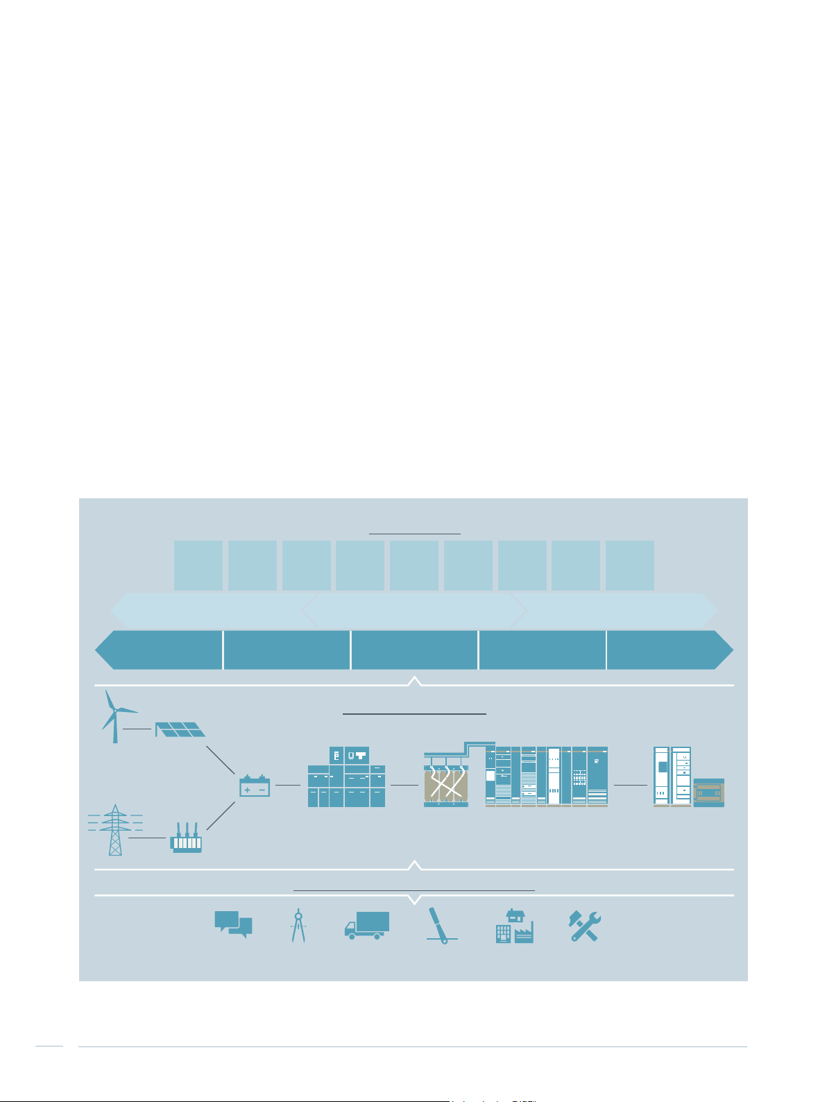
Comparable to a main artery, electric power supply constitutes the basis for reliable and efficient functioning of all
electrically operated facilities. Electrical power distribution
requires integrated solutions. Totally Integrated Power (TIP)
is a synonym for integrated electrical power distribution
(Fig. 1/1) in industrial applications, infrastructure projects
and buildings.
SIMARIS planning tools
The SIMARIS planning tools by Siemens provide efficient
support for dimensioning electric power distribution systems and determine the devices and distribution boards
required for them.
• SIMARIS design for network calculation and dimensioning
• SIMARIS project for determining the space requirements
of distribution boards and the budget, and for generating
specifications (bills of quantities)
• SIMARIS curves for visualising characteristic tripping
curves, cut-off current and let-through energy curves.
Further information about TIP:
www.siemens.com/tip
Further information about SIMARIS:
www.siemens.com/simaris
Fig. 1/1: Totally Integrated Power (TIP) as holistic approach to electric power distribution
4
SIVACON S8 Planning Principles – System-based power distribution
SIMARIS configuration tools
Tested safety
Configuring and dimensioning a low-voltage switchboard is
very complex. SIVACON S8 switchboards are configured by
experts, effectively supported by the SIMARIS configuration
tools during the stages of switchboard manufacture, operation and maintenance:
• SIMARIS configuration for tender drawing up, order
processing and manufacturing the SIVACON S8
switchboard
• SIMARIS control to efficiently create visualisation systems
for operating and monitoring the SIVACON S8
switchboard
Cost-efficient complete system
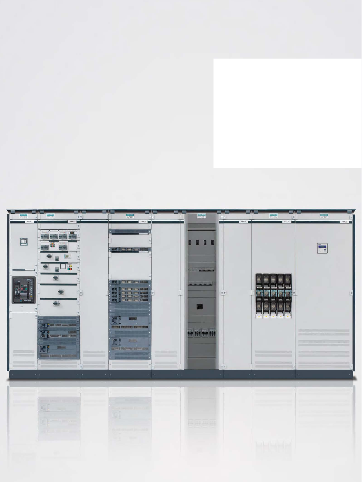
The SIVACON S8 low-voltage switchboard sets new standards worldwide as power distribution board (PDB) or motor
control center (MCC) for industrial applications or in infrastructure projects (Fig. 1/2). The switchboard system up to
7,000 A for easy and integrated power distribution ensures
maximum personal safety and plant protection and provides many possibilities for use due to its optimal design. Its
modular construction allows the switchboard to be optimally matched to any requirement when the whole plant is
designed. Maximum safety and modern design now complement each other in an efficient switchboard.
SIVACON S8 is a synonym for safety at the highest level.
The low-voltage switchboard is a design-verified low-voltage switchgear and controlgear assembly in accordance
with IEC 61439-2. Design verification is performed by
testing. Its physical properties were verified in the test area
both for operating and fault situations. Maximum personal
safety is also ensured by a test verification under arcing
fault conditions in accordance with IEC/TR 61641.
Flexible solutions
The SIVACON S8 switchboard is the intelligent solution
which adapts itself to your requirements. The combination
of different mounting designs within one cubicle is unique.
The flexible, modular design allows functional units to be
easily replaced or added. All SIVACON S8 modules are
subject to a continuous innovation process and the complete system always reflects the highest level of technical
progress.
Further information about SIVACON S8:
www.siemens.com/sivacon-s8
1
2
3
4
5
6
Motor control center
Power distribution from the power center to the main and subdistribution board
Chemical &
mineral oil industry
Fig. 1/2: SIVACON S8 for all areas of application
Power industry:
Power plants
and auxiliary systems
SIVACON S8 Planning Principles – System-based power distribution
Capital goods industry:
Production-related systems
Infrastructure:
Building complexes
7
8
9
10
11
5

Use
Advantages of modular design
SIVACON S8 can be used at all application levels in the
low-voltage network (Fig. 1/3):
• Power center or secondary unit substation
• Main switchboard or main distribution board
• Subdistribution board, motor control center, distribution
board for installation devices or industrial use
Power center
Every SIVACON S8 switchboard is manufactured of demand-oriented, standardised, and series-produced modules. All modules are tested and of a high quality. Virtually
every requirement can be satisfied due to the manifold
module combination possibilities. Adaptations to new
performance requirements can easily and rapidly be implemented by replacing or adding modules.
The advantages offered by this modular concept are clear:
• Verification of safety and quality for every switchboard
• Fulfilment of each and every requirement profile
combined with the high quality of series production
• Easy placement of repeat orders and short delivery time
Main distribution
board
Subdistribution
boards
Consumers load
Fig. 1/3: Use of SIVACON S8 in power distribution
6
SIVACON S8 Planning Principles – System-based power distribution
M M M
Motor
control
center (MCC)
M
Chapter 2
SIVACON S8 – System overview
2.1 System configuration and
cubicle design 10
2.2 Corner cubicle 15
2.3 Main busbar, horizontal 16
2.4 Connection points for earthing and
short-circuit devices 17
2.5 Overview of mounting designs 18
2 SIVACON S8 – System overview
The interaction of the components described below results
in an optimal low-voltage switchboard with advantages as
regards:
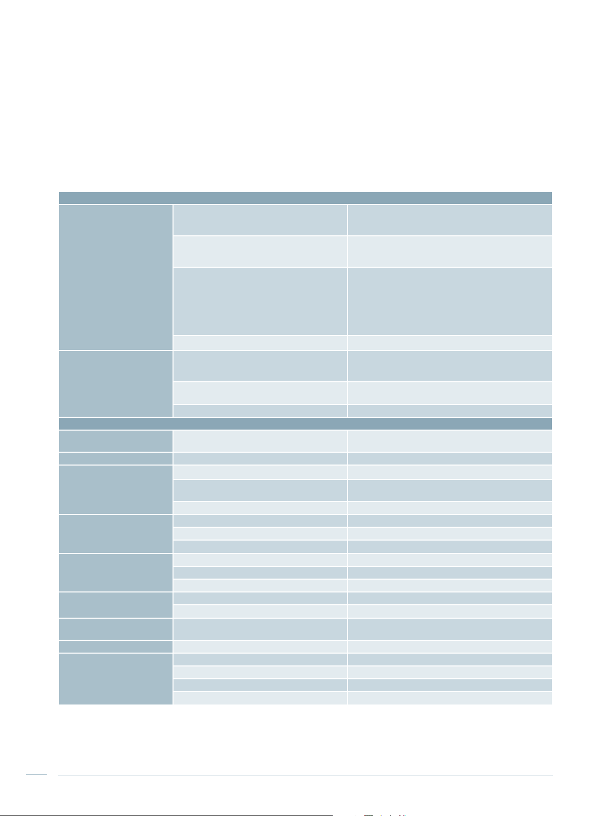
Tab. 2/1: Technical data, standards and approvals for the SIVACON S8 switchboard
Standards and approvals
Standards and regulations Power switchgear and controlgear assembly
Approvals Europe
Technical data
Installation conditions Indoor installation, ambient temperature in the
Rated operating voltage (U
Dimensioning of creepage
distances and clearances
Main busbars, horizontal Rated current Up to 7,010 A
Rated device currents Circuit-breakers Up to 6,300 A
Internal separation IEC 61439-2 Form 1 to form 4
IP degree of protection in accordance with IEC 60529 Ventilated up to IP43
Mechanical strength IEC 62262 Up to IK10
Dimensions Height (without base) 2,000, 2,200 mm
(design verification)
Test of internal fault behaviour (internal arc) IEC/TR 61641
Induced vibrations IEC 60068-3-3
Protection against electric shock EN 50274 (VDE 0660-514)
Russia, Belarus, Kasakhstan
China
Det Norske Veritas
Lloyds Register of Shipping
Shell conformity "DEP Shell"
24-h mean
Main circuit
e)
Rated impulse withstand voltage U
Rated
insulation voltage (U
Degree of pollution 3
Rated peak withstand current (I
Rated short-time withstand current (I
Cable feeders Up to 630 A
Motor feeders Up to 630 A
BS EN 61439-2 Up to form 4 type 7
Height of base (optional) 100, 200 mm
Cubicle width 200, 350, 400, 600, 800, 850, 1,000, 1,200, 1,400 mm
Depth (single-front) 500, 600, 800, 1,000, 1,200 mm
)
i
• Safety - integrated
• Economic efficiency - right from the start
• Flexibility – through modularity
IEC 61439-2
DIN EN 61439-2-2
VDE 0660-600-2
DIN EN 60439-1 Supplement 2
VDE 0660-500 Supplement 2
IEC 60068-2-6
IEC 60068-2-57
IEC 60980
KTA 2201.4
Uniform Building Code (UBC), Edition 1997 Vol. 2,
Ch. 19, Div. IV
CE marking and EC Declaration of Conformity
EAC
CCC
DNV GL Type Approval Certificate
LR Type Approval Certificate
+ 35 °C
(-5 °C to + 40 °C)
Up to 690 V (rated frequency fn 50 Hz)
imp
)
pk
)
cw
8 kV
1,000 V
Up to 330 kA
Up to 150 kA, 1s
Non-ventilated IP54
8
SIVACON S8 Planning Principles – SIVACON S8 – System overview
1
1
10
11
21
9
20
19
18
8
7
15
14
6
17
16
4
2
2
12
3
4
3
13
5
6
5
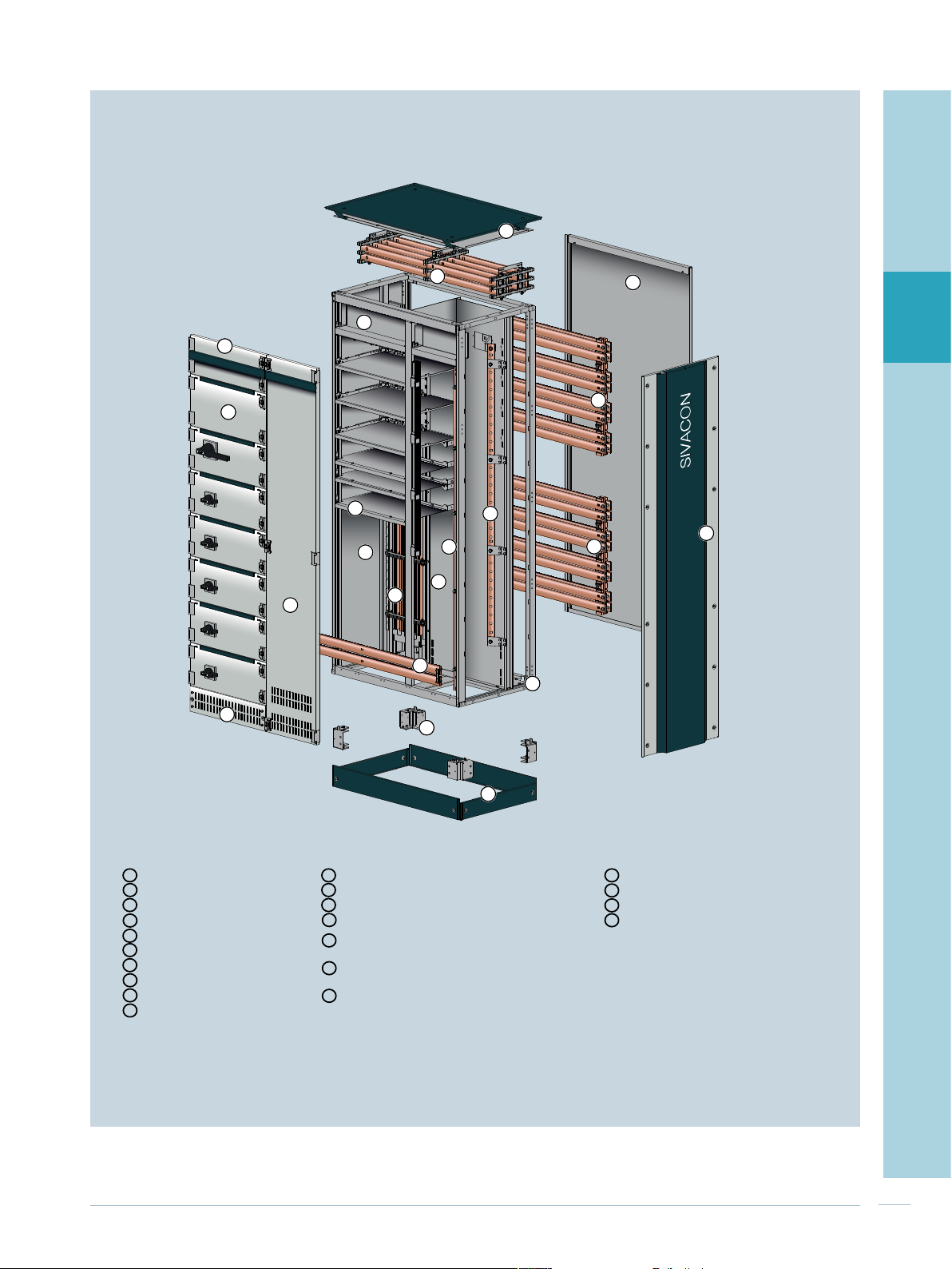
Enclosure Busbars Internal separation
Roof plate Main busbar (L1... L3, N) – top Device compartment/busbar compar tment
1 11 18
Rear panel Main busbar (L1... L3, N) – rear top Cubicle to cubicle
2 12 19
Design side panel Main busbar (L1... L3, N) – rear bottom Compartment to compartment
3 13 20
Frame Main busbar (PE) – bottom Cross-wiring compartment
4 14 21
Base cover
5
Base
6
Ventilated base compartment cover
7
Ventilated cubicle door
8
Compartment door
9
Head room door
10
Fig. 2/1: Cubicle design of SIVACON S8
Vertical distribution busbar system (L1... L3, N)
15
device compartment
Vertical distribution busbar (PE)
16
cable connection compartment
Vertical distribution busbar (N)
17
cable connection compartment
SIVACON S8 Planning Principles – SIVACON S8 – System overview
7
8
9
10
11
9
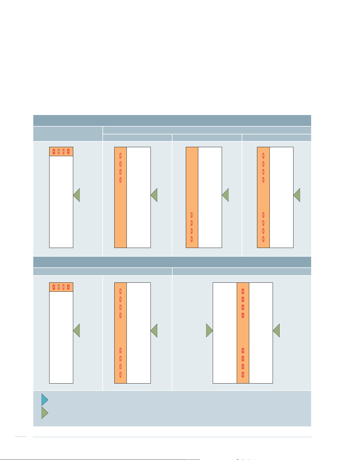
2.1 System configuration and
cubicle design
When the system configuration is planned, the following
characteristics must be specified:
• Busbar position (top, rear top, rear bottom, or both rear
top and rear bottom)
Tab. 2/2: Schematic overview of switchboard configurations for SIVACON S8
Busbar position
Top
Rear
Top Bottom Top and bottom
• Single-front or double-front design
• Cable/busbar entry (from the top or bottom)
• Connection in cubicle (front or rear)
B B B B
Single-front / double-front design
Single front Double front
B B
Side of connection
A
Operating panel
B
B
B
10
SIVACON S8 Planning Principles – SIVACON S8 – System overview
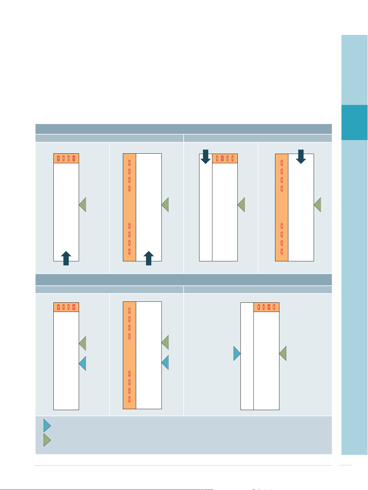
These characteristics depend on the type of installation
among other things:
• Stand-alone
• At the wall (only for single-front design)
• Back to back (only for single-front design)
These determinations allow to specify cubicle design in
more detail (Fig. 2/1, Tab. 2/2 and Tab. 2/3). Further information about the switchboard installation can be found in
Chapter 8 “Further planning notes”.
1
Cable/busbar entry
From the bottom From the top
B
Connection in cubicle
Front Rear
B
2
3
4
B
B
5
6
7
Side of connection
A
Operating panel
B
8
B
A
B
A
A
B
9
10
11
SIVACON S8 Planning Principles – SIVACON S8 – System overview
11
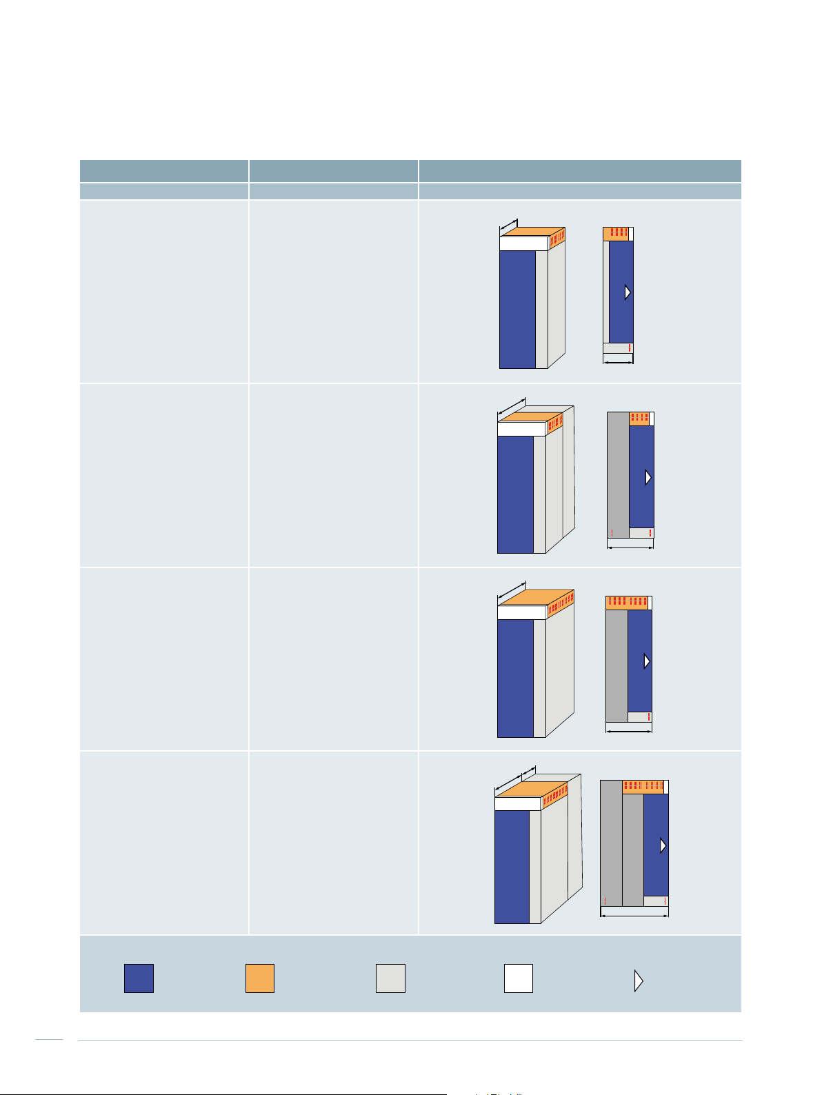
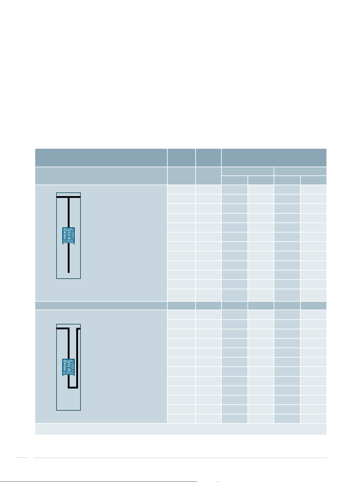
Tab. 2/3: Cubicle types and busbar arrangement
Top busbar position
Busbar system Cubicle design
Busbar position
Rated current
Cable/busbar entry
Connection in cubicle
Top
Up to 3,270 A
Bottom
Front
500
800
N L3 L2 L1
500
PE
N L3 L2 L1
Busbar position
Rated current
Cable/busbar entry
Connection in cubicle
Busbar position
Rated current
Cable/busbar entry
Connection in cubicle
Busbar position
Rated current
Cable/busbar entry
Connection in cubicle
Top
Up to 3,270 A
Top
Front or rear
Top
Up to 6,300 A
Bottom
Front
Top
Up to 6,300 A
Top
Front or rear
PE
PE
800
800
N L3 L2 L1
N L3 L2 L1
PE
800
400
800
N L3 L2 L1
N L3 L2 L1
Device/functional
compartment
12
SIVACON S8 Planning Principles – SIVACON S8 – System overview
Busbar
compartment
Cable / busbar
connection
compartment
Cross-wiring
compartment
1,200
PE
PE
Operating
panels
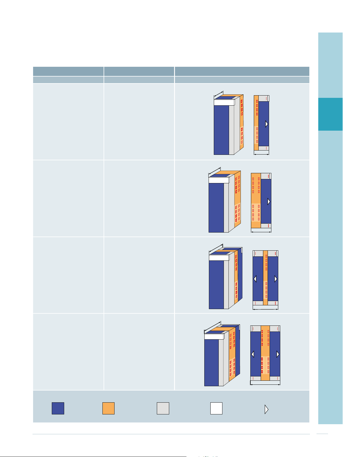
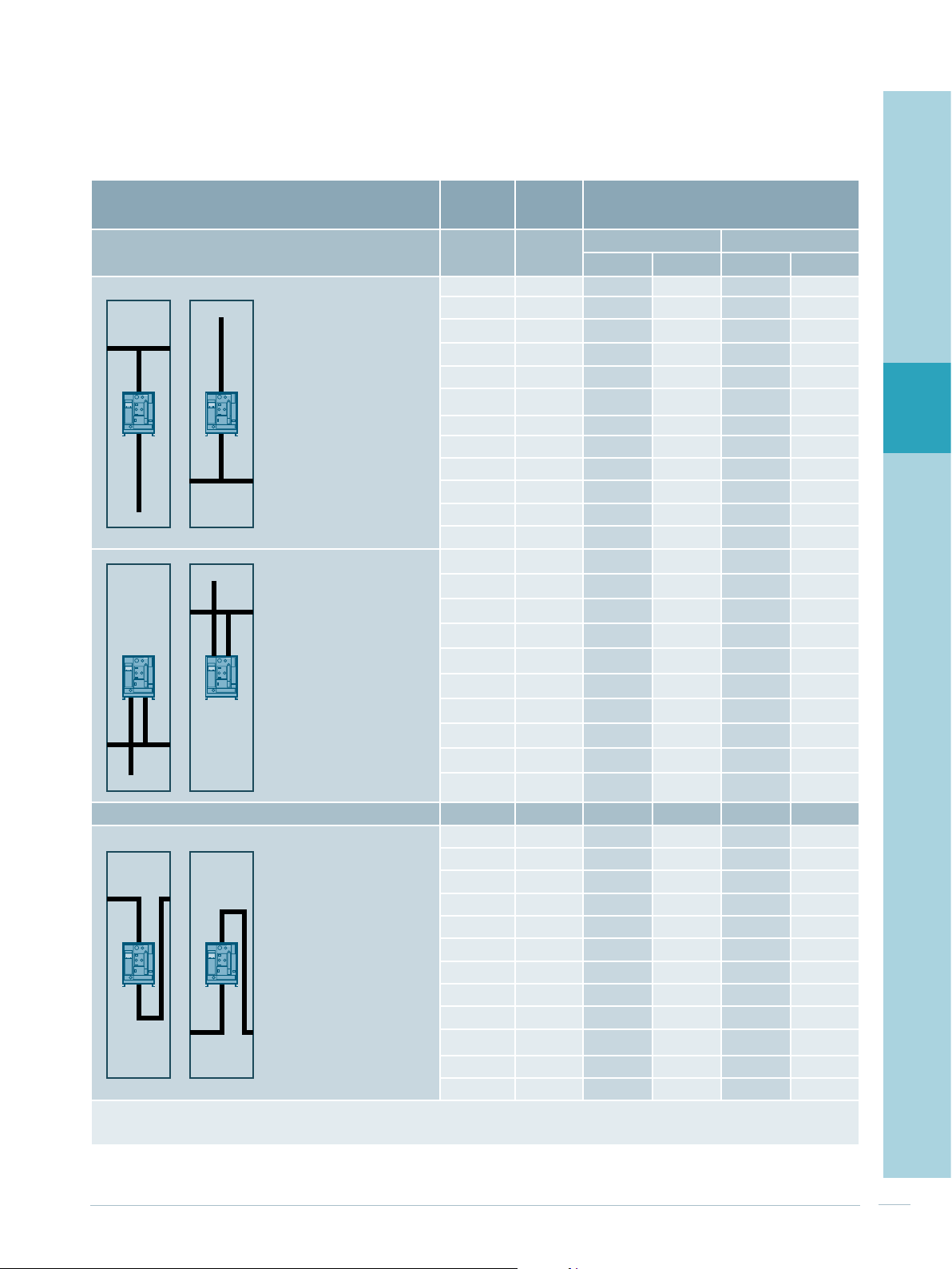
Rear busbar position
Busbar system Cubicle design
Rear
Busbar position
Top or bottom
Top and bottom
Rated current
Cable/busbar entry
Connection in cubicle
Busbar position
Up to 4,000 A
Bottom or top
Front
Rear
Top or bottom
Rated current
Cable/busbar entry
Connection in cubicle
Up to 7,010 A
Bottom or top
Front
800
600
1
PE
N
L1
L2
L3
L1
L2
L3
N
PE
600
PE
N
L1
L2
L3
L1
L2
L3
N
PE
800
2
3
4
5
Busbar position
Rated current
Cable/busbar entry
Connection in cubicle
Busbar position
Rated current
Cable/busbar entry
Connection in cubicle
Device/functional
compartment
Rear
Top or bottom
Top and bottom
Up to 6,300 A
Bottom or top
Front
Rear
Top or bottom
Up to 7,010 A
Bottom, top
Front
Busbar
compartment
Cable / busbar
connection
compartment
1,000
1,200
Cross-wiring
compartment
PE
PE
N
L1
L2
L3
L1
L2
L3
N
PE
PE
1,000
7
8
6
N
L1
L2
L3
L1
L2
L3
N
1,200
N
L1
L2
L3
L1
L2
L3
N
PE
PE
Operating
panels
9
10
11
PE
PE
SIVACON S8 Planning Principles – SIVACON S8 – System overview
13
Tab. 2/4: Cubicle dimensions
Cubicle height
Frame 2,000, 2,200 mm
Base Without, 100, 200 mm
Cubicle width
Dependent of:
Cubicle depth
Type
Single front
Double front Rear
1)
Frame height 2,200 mm
- Cubicle type
- Rated device current
- Connecting position and/or cable/busbar entry
Main busbar Cubicle depth
Location Rated current Front connection Rear connection
Top
Rear
Entry from the
bottom
3,270 A 500, 800 mm 800 mm 800 mm
1)
6,300 A
4,000 A 600 mm 600 mm -
7,010 A 800 mm 800 mm -
4,000 A 1,000 mm 1,000 mm -
1)
7,010 A
800, 1,000 mm 1,200 mm 1,200 mm
1,200 mm 1,200 mm -
Entry from the top
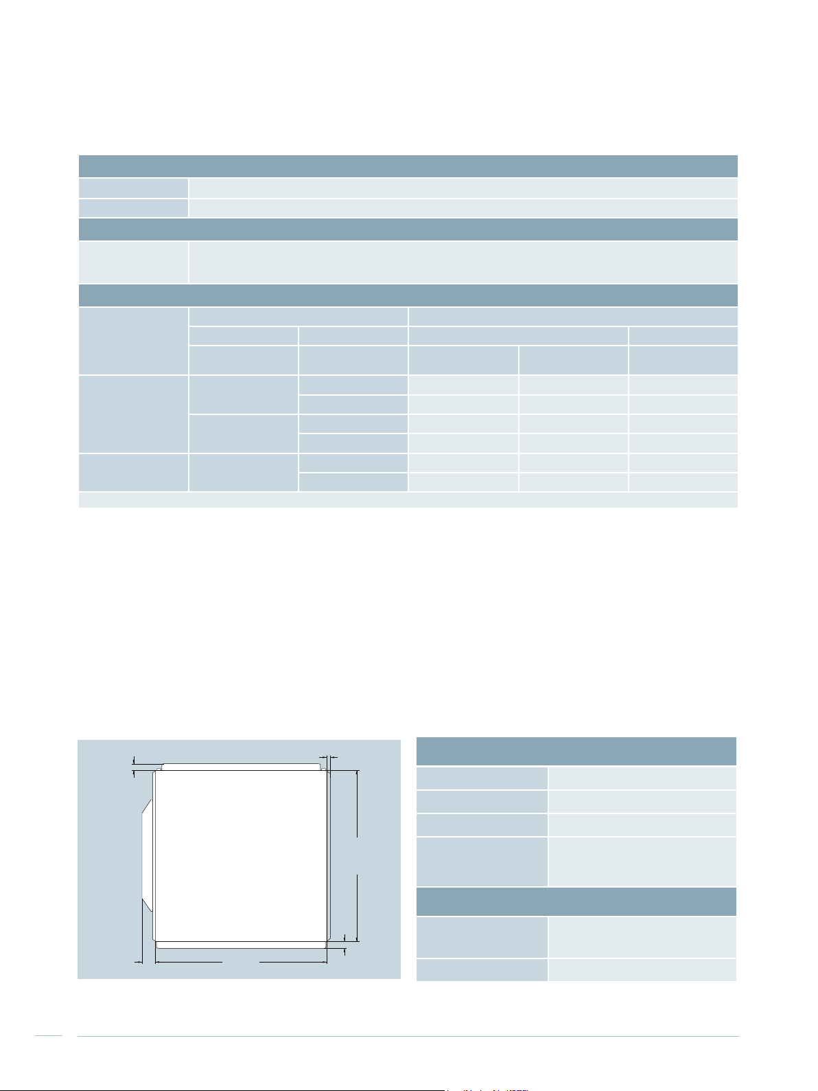
The cubicle dimensions listed in Tab. 2/4 do not factor in
the enclosure parts and no outer built-on parts.
For the dimensions of the cubicles' enclosure parts, please
refer to Fig. 2/2. For degrees of protection IPX1 and IPX3,
additional ventilation roof panels are mounted on the
cubicle.
The dimensions of the enclosure parts are within the
required minimum clearances for erecting the switchboard.
Doors can be fitted so that they close in escape direction.
9 mm
25 mm
Rear panel
Side panel
with
design strip
45 mm
Door
Width
Side panel
without
design strip
Depth
25 mm
The door stop can easily be changed later. The door hinges
allow for a door opening angle of up to 180° in case of
single installation of a cubicle and at least 125° when
cubicles are lined up. For more details, please refer to
Chapter 8 “Further planning notes”. The condition of surfaces of structural and enclosure parts is described in
Tab. 2/5.
Tab. 2/5: Surface treatment
Surface treatment
Frame components Sendzimir-galvanised
Enclosure Sendzimir-galvanised / powder-coated
Doors Powder-coated
Copper bars
Colour
Powder-coated
components
(layer thickness 100 ± 25 μm)
Design components Blue Green Basic
Bare copper,
optionally silver-plated,
optionally tin-plated
RAL7035, light grey (in accordance
with DIN 43656) or upon request
Fig. 2/2: Dimensions of enclosure parts
14
SIVACON S8 Planning Principles – SIVACON S8 – System overview
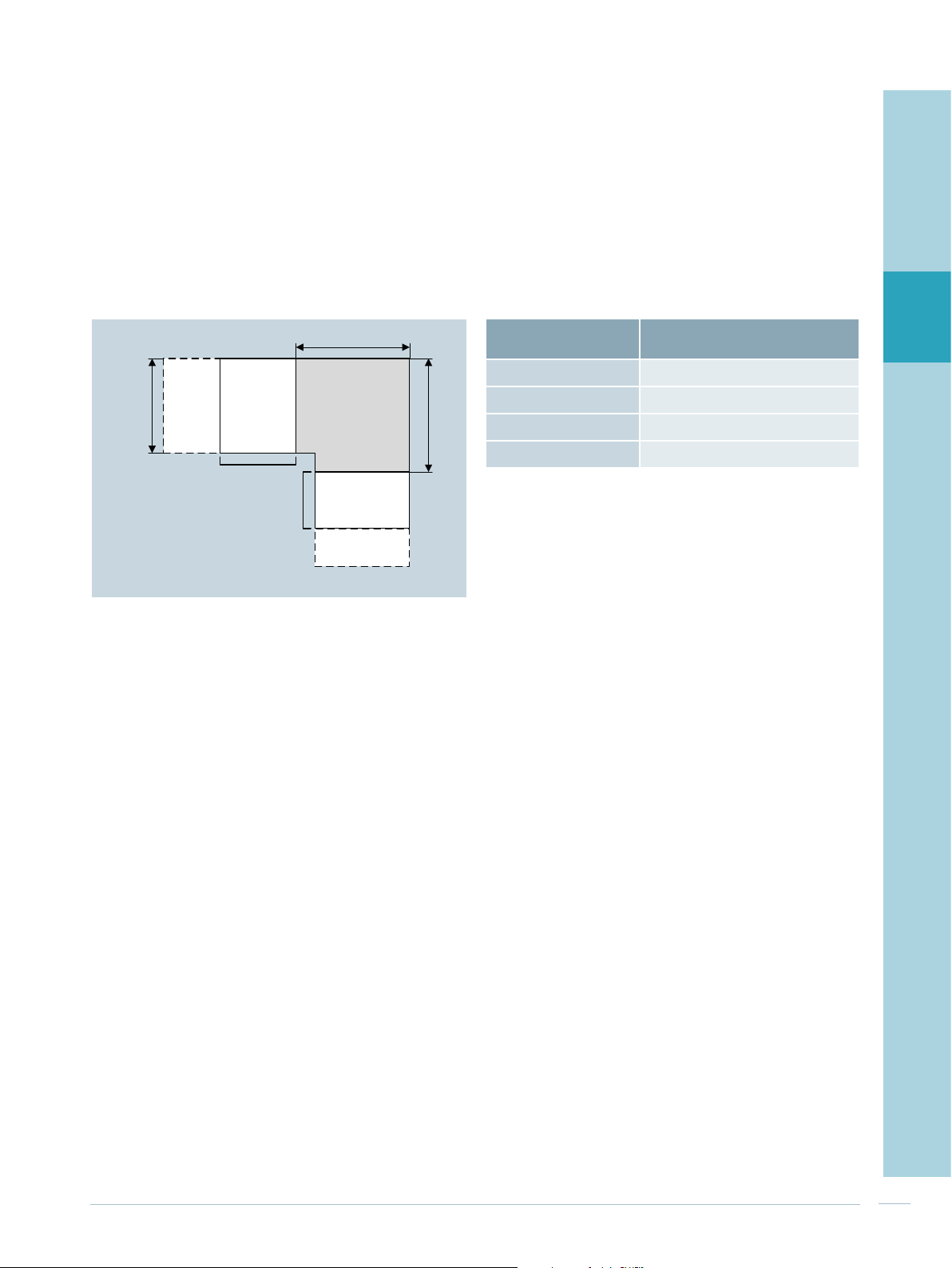
2.2 Corner cubicle
The corner cubicle connects two segments, positioned at
right angles to each other, of a switchboard in single-board
design (Fig. 2/3). The corner cubicle contains as functional
rooms only the busbar compartment and the cross-wiring
compartment. These compartments cannot be accessed via
doors. The frame width resp. frame depth of the cubicles
are listed in Tab. 2/6.
1
Tab. 2/6: Dimensions of the corner cubicles
D
Operation panel
Fig. 2/3: Integration of the corner cubicle
Corner cubicle
W
W
Cubicle depth D
500 mm 600 mm
600 mm 700 mm
800 mm 900 mm
1,200 mm 900 mm
Frame width / depth W
of the corner cubicle
2
3
4
5
6
7
SIVACON S8 Planning Principles – SIVACON S8 – System overview
8
9
10
11
15
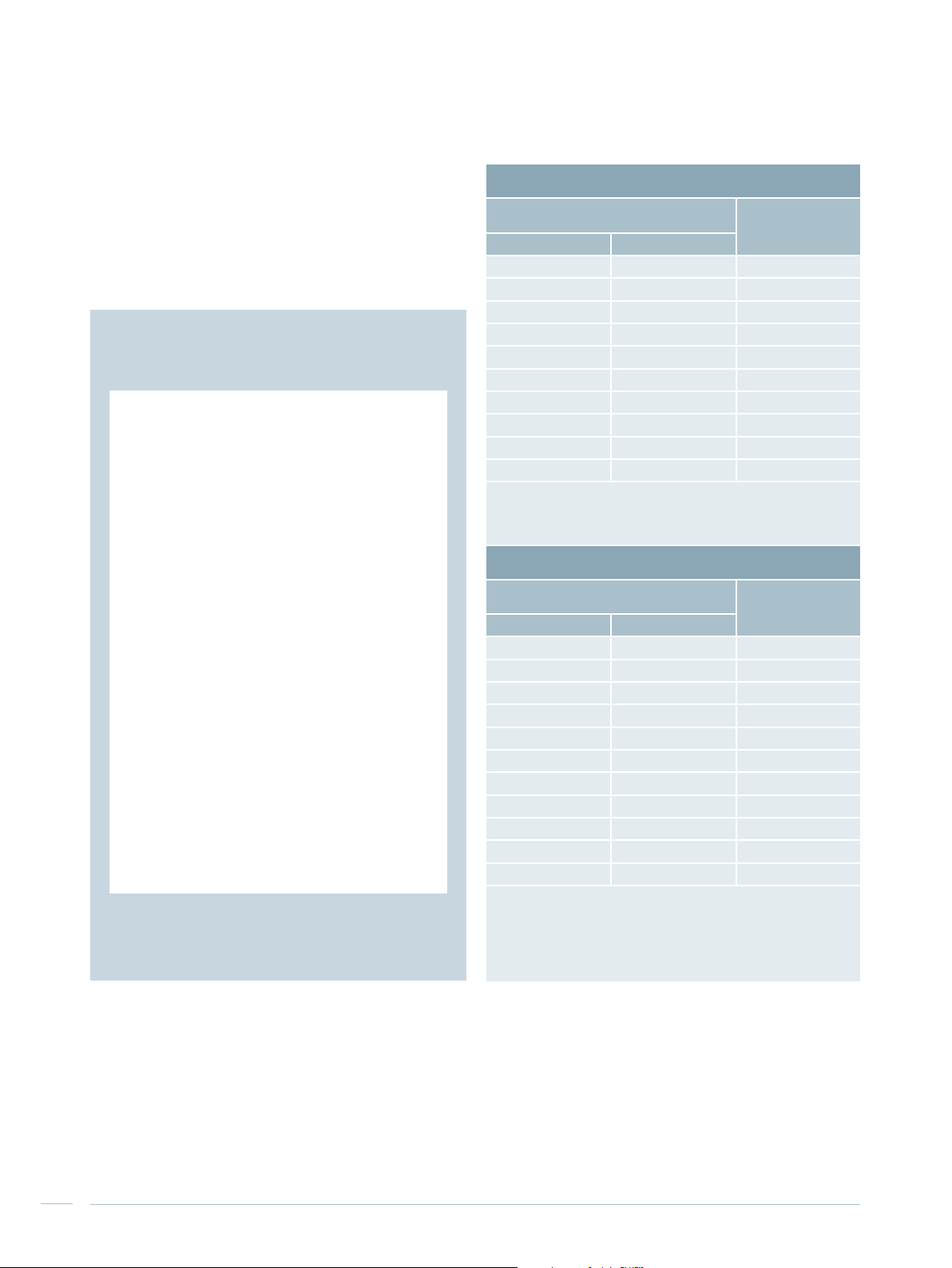
2.3 Main busbar, horizontal
Tab. 2/7 lists the rating data for the two possibilities how to
position the main busbar – top or rear – (Fig. 2/4). Chapter
10 describes how ambient temperatures must be observed
in respect of the current carrying capacity.
Tab. 2/7: Rating of the main busbar
Top busbar position
Rated current I
temperature
Ventilated Non-ventilated
at 35 °C ambient
n
Rated short-time
withstand current
I
(1 s)
cw
1,190 A 965 A 35 kA
1,630 A 1,310 A 50 kA
1,920 A 1,480 A 65 kA
2,470 A 1,870 A 85 kA
3,010 A 2,250 A 100 kA
3,270 A 2,450 A 100 kA
1)
3,700 A
1)
4,660 A
1)
5,620 A
1)
6,300 A
1)
If circuit-breakers with a very high power loss are used, the
3,000 A
3,680 A
4,360 A
4,980 A
1)
1)
1)
1)
100 kA
100 kA
150 kA
150 kA
following correction factors must be applied:
3WL1350: 0.95
3WL1363: 0.88
Rear busbar position
Rated current In at 35 °C ambient
temperature
Ventilated Non-ventilated
1)
Rated short-time
withstand current
I
(1 s)
cw
1,280 A 1,160 A 50 kA
1,630 A 1,400 A 65 kA
2,200 A 1,800 A 65 kA
2,520 A 2,010 A 85 kA
2,830 A 2,210 A 100 kA
3,170 A 2,490 A 100 kA
4,000 A 3,160 A 100 kA
2)
4,910 A
2)
5,340 A
2)
5,780 A
2)
7,010 A
1)
When operating two systems per cubicle at the same time
3,730 A
4,080 A
4,440 A
5,440 A
2)
2)
2)
2)
100 kA
100 kA
100 kA
150 kA
(busbar position rear top and rear bottom),
a reduction factor has to be considered::
for ventilated boards: 0,94
for unventilated boards: 0,98
2)
Busbar position rear top or rear bottom
Fig. 2/4: Variable busbar position for SIVACON S8
16
SIVACON S8 Planning Principles – SIVACON S8 – System overview

2.4 Connection points for earthing
and short-circuit devices
Short-circuiting and earthing devices (SED)
For short-circuiting and earthing, short-circuiting and
earthing devices (SED) are available. For mounting the SED,
appropriate fastening points are fitted at the points to be
earthed. To accommodate the SED for the main busbar, a
cubicle for customized solutions is inserted (see Chapter
6.3 “Cubicle for customized solutions”). The cubicle widths
are given in Tab. 2/8.
Central earthing point (CEP) and main earthing busbar
(MEB)
When voltage sources, which are located far apart, are
earthed, for example secondary unit substation and
standby generator set, the separate earthing of their neutral points results in compensating currents through foreign
conductive building structures. Undesired electro-magnetic
interference is created, caused by the building currents on
the one hand and the lack of summation current in the
respective cables on the other.
If the requirement is parallel operation of several voltage
sources and if building currents shall be reduced as far as
possible, the preferable technical solution is implementing
the central earthing point (CEP). In this case, the neutral
points of all voltage sources are connected to the system
protective conductor / system earth at a single point only.
The effect is that despite potential differences of the
neutral points, building currents cannot be formed any
more.
Tab. 2/8: Cubicle widths for earthing short-circuit points
The central earthing point can only be used in the
power supply system L1, L2, L3, PEN (insulated) + PE.
To implement the central earthing point (CEP) - with or
without a main earthing busbar (MEB) - a cubicle for
customized solutions is inserted (see Chapter 6.3 “Cubicle
for customized solutions”).
CEP design
The CEP is designed as a bridge between the separately
wired (insulated) PEN and the PE conductor of the switchboard. Measuring current transformers can be mounted on
the bridge for residual current measurements. In order to
be able to remove the current transformer in case of a
defect, a second, parallel bridge is provided. This prevents
cancelling the protective measure due to a missing connection between the separately wired PEN and PE conductor.
A mounting plate in the cubicle is provided for placing the
residual-current monitors. The cubicle widths are given in
Tab. 2/8.
MEB design
In addition to the central earthing point, the MEB can
optionally be mounted as a horizontal bar. This connecting
bar is separately installed in the cubicle and rigidly connected to the PE conductor. Depending on how the cable is
entered, the MEB is installed at the top or bottom of the
cubicle. The cubicle widths can be found in Tab. 2/8 and
information about the cable terminals can be found in
Tab. 2/9.
Tab. 2/9: Cable terminal for the main earthing busbar
1
2
3
4
5
6
7
Earthing and shortcircuit points
Short-circuiting and
earthing devices (SED)
Central earthing point
(CEP)
Main earthing busbar
(MEB)
Cubicle widths
400 mm (200 mm as cubicle
extension)
600 mm, 1,000 mm (200 mm as
cubicle extension)
600 mm, 1,000 mm
Cubicle width
600 mm 10 x 185 mm
1,000 mm 20 x 185 mm2 (M10) + 22 x 240 mm2 (M12)
1)
300 mm² cable lugs can be used with M12 screw,
but this cable lug does not comply with DIN 46235, although it is
supplied by some manufacturers.
SIVACON S8 Planning Principles – SIVACON S8 – System overview
Max. number of cables connectible with
cable lug DIN 46235 (screw)
2
(M10) + 12 x 240 mm2 (M12)
1)
1)
8
9
10
11
17

2.5 Overview of mounting designs
Tab. 2/10: Basic data of the different mounting designs
Circuit-breaker design Universal mounting design In-line design, plug-in Fixed-mounted design
Mounting design
Functions
Rated current I
Connection type Front and rear side Front and rear side Front side Front side Front side Front side
Cubicle width 400, 600, 800, 1,000, 1,400 mm 600, 1,000, 1,200 mm 1,000, 1,200 mm 1,000, 1,200 mm 600, 800, 1,000 mm 800 mm
Internal separation Form 1, 2b, 3a, 4b, 4 type 7 (BS) Form 3b, 4a, 4b, 4 type 7 (BS) Form 3b, 4b Form 1, 2b, 3b, 4a, 4b Form 1, 2b Form 1, 2b
Busbar position Rear, top Rear, top Rear, top Rear, top Rear Rear, top, without
18
SIVACON S8 Planning Principles – SIVACON S8 – System overview
n
Withdrawable design
Fixed mounted design
Incoming unit
Outgoing unit
Coupler
Up to 6,300 A Up to 630 A Up to 630 A Up to 630 A Up to 630 A
Withdrawable design
Fixed-mounted design with compartment doors
Plug-in design
Cable feeders
Motor feeders (MCC)
Plug-in design Fixed-mounted design with front covers Fixed mounted design Fixed mounted design
Cable feeders Cable feeders Cable feeders Central compensation of reactive power

1
2
3
4
5
6
In-line design,
fixed-mounted
Reactive power compensation
Non-choked up to 600 kvar
Choked up to 500 kvar
SIVACON S8 Planning Principles – SIVACON S8 – System overview
7
8
9
10
11
19

20
SIVACON S8 Planning Principles – SIVACON S8 – System overview
Chapter 3
Circuit-breaker design
3.1 Cubicles with one ACB (3WL) 24
3.2 Cubicles with up to three ACB (3WL) 29
3.3 Cubicles with one MCCB (3VL) 30
3.4 Cubicles for direct supply and
direct feeder 31

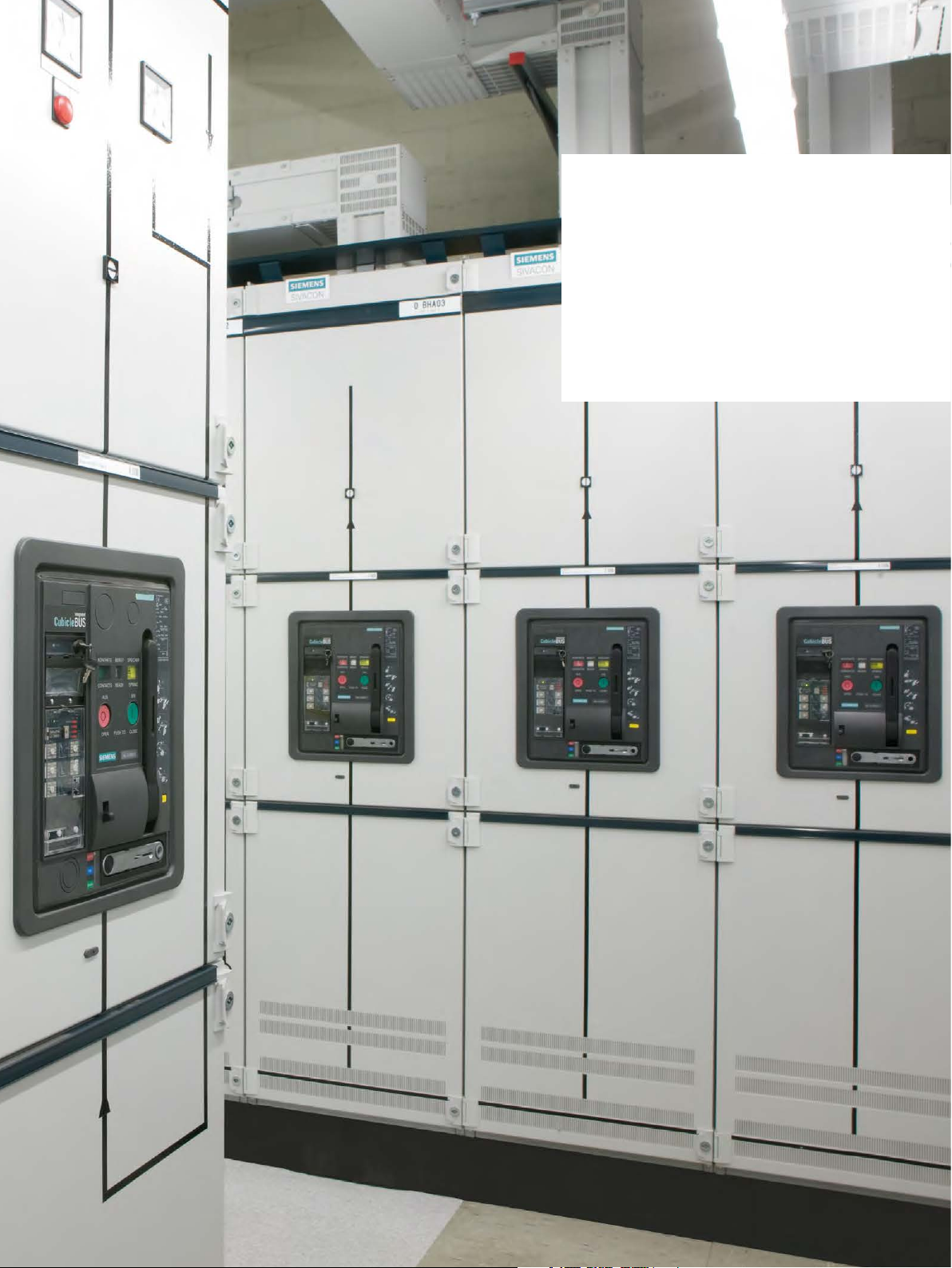
3 Circuit-breaker design
The cubicles for 3W. and 3V. circuit-breakers ensure both
personal safety and long-term operational safety (Fig. 3/1).
The incoming, outgoing and coupling units in circuit-breaker design are equipped with 3W. air circuit-breakers (ACB) in withdrawable or fixed-mounted design or
alternatively with 3V. moulded-case circuit-breakers (MCCB)
(Tab. 3/1).
The cubicle dimensions are tailored to the circuit-breaker
sizes and can be selected according to the individual requirements. The circuit-breaker design provides optimal
connect conditions for every nominal current range. In
addition to cable connections, the system also provides
design-verified connections to SIVACON 8PS busbar trunking systems.
Fig. 3/1: Cubicles in circuit-breaker design
22
SIVACON S8 Planning Principles – Circuit-breaker design

Tab. 3/1: General cubicle characteristics in circuit-breaker design
Application
range
Degrees of protection - Up to IP43 Ventilated
Form of internal separation - Form 1, 2b Door cubicle high
Design options - Air circuit-breaker (ACB) in fixed-mounted or withdrawable design
1)
Also form 4b type 7 in acc. with BS EN 61439-2 possible
2)
Information about 3WT circuit-breakers is available from your Siemens contact
3)
Information about moulded-case circuit-breakers in plug-in/withdrawable design is available from your Siemens contact
The circuit-breaker cubicles allow the installation of a
current transformer (L1, L2 and L3) at the customer connection side. Information about the installation of additional transformers is available from your Siemens contact.
Cubicle with forced cooling
The circuit-breaker cubicles with forced cooling are
equipped with fans (Fig. 3/2). Controlled fans are installed
in the cubicle front below the circuit-breaker. The forced
cooling makes for an increase of the rated current of the
circuit-breaker cubicle. The other cubicle characteristics are
identical to the cubicle without forced cooling.
- Incoming circuit-breakers
- Coupling circuit-breakers (longitudinal and transverse couplers)
- Outgoing circuit-breakers
- Direct incoming/outgoing feeders (without circuit-breakers)
- IP54 Non-ventilated
- Form 3a, 4b
- Moulded-case circuit-breaker (MCCB) in fixed-mounted design
1)
Door divided in 3 parts
2)
3)
1
2
3
4
5
The fan control comes completely configured. No further
settings are required upon start-up of the switchboard. The
fans are dimensioned such that the required cooling is still
ensured if a fan fails. Failure of the fan or non-permissible
temperature rises are signalled. Forced cooling is available
for selected ACB (3WL) in withdrawable design.
The use of fans brings about additional noise emission.
Under normal operating conditions, the noise emission
may be 85 dB at the maximum. Higher noise emissions
only occur in the case of a fault.
Observing local regulations on noise protection and occupational safety and health is mandatory. Rating data for
cubicles with forced cooling is available from your
Siemens contact.
6
7
8
9
Fig. 3/2: Forced cooling in a circuit-breaker cubicle
10
11
SIVACON S8 Planning Principles – Circuit-breaker design
23
3.1 Cubicles with one ACB (3WL)
The widths for the different cubicle types are listed by ACB
type in Tab. 3/2 to Tab. 3/4.
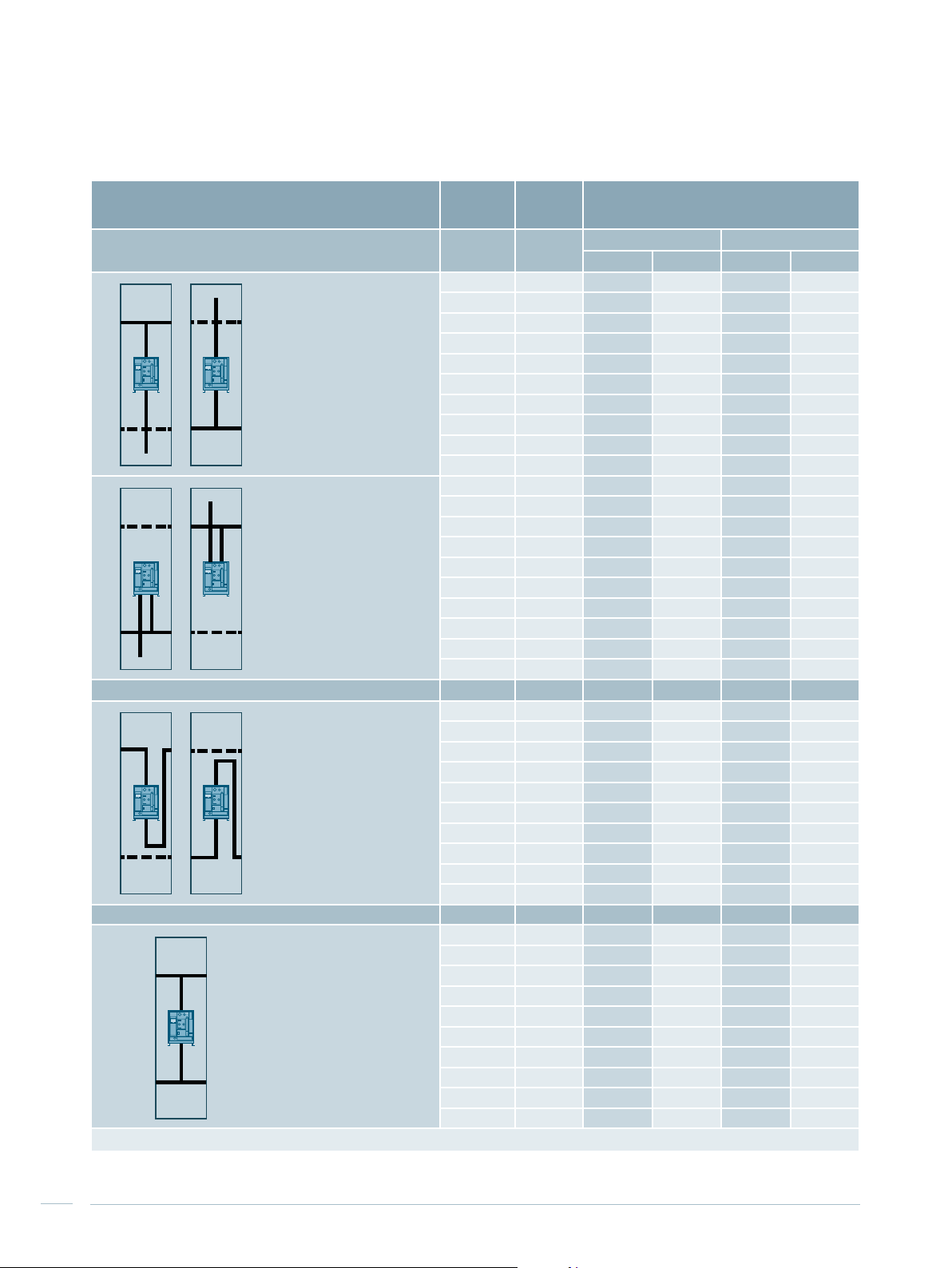
Tab. 3/2: Cubicle dimensions for top busbar position
Cubicle type
ACB type
Nominal
device
Cubicle width in mm
current
Incoming / outgoing unit
Cable connection Busbar connection
3-pole 4-pole 3-pole 4-pole
3WL1106 630 A 400/600 600 - -
3WL1108 800 A 400/600 600 - -
3WL1110 1,000 A 400/600 600 - -
3WL1112 1,250 A 400/600 600 - -
Top busbar position,
cable / busbar entry from the
top or bottom
3WL1116 1,600 A 400/600 600 400/600 600
3WL1120 2,000 A 400/600 600 400/600 600
3WL1220 2,000 A 600/800 800 600/800 800
3WL1225 2,500 A 600/800 800 600/800 800
3WL1232 3,200 A 600/800 800 600/800 800
2)
800 1,000 800 1,000
The position of the connecting bars is identical for cable entry
from the top or bottom
3WL1340 4,000 A
1)
3WL1350
3WL1363
5,000 A 2)- - 1,000 1,000
1)
6,300 A 2)- - 1,000 1,000
Longitudinal coupler 3-pole 4-pole
3WL1106 630 A 600 800 - -
3WL1108 800 A 600 800 - -
3WL1110 1,000 A 600 800 - -
3WL1112 1,250 A 600 800 - -
3WL1116 1,600 A 600 800 - -
Top busbar position
3WL1120 2,000 A 600 800 - -
3WL1220 2,000 A 800 1,000 - -
3WL1225 2,500 A 800 1,000 - -
3WL1232 3,200 A 800 1,000 - -
2)
1,000 1,200 - -
1)
Withdrawable design, frame height 2,200 mm
2)
Main busbar up to 6,300 A
3WL1340 4,000 A
1)
3WL1350
3WL1363
5,000 A 2)1,200 1,200 - -
1)
6,300 A 2)1,200 1,200 - -
24
SIVACON S8 Planning Principles – Circuit-breaker design
Tab. 3/3: Cubicle dimensions for rear busbar position
Cubicle type
Incoming / outgoing unit
1 busbar system in the cubicle:
rear top busbar position and
cable / busbar entry from the
bottom
or
rear bottom busbar position
and
cable / busbar entry from the
top
1 busbar system in the cubicle:
rear bottom busbar position
and
cable / busbar entry from the
bottom
or
rear top busbar position and
cable / busbar entry from the
top
Longitudinal coupler 3-pole 4-pole
1 busbar system in the cubicle:
rear top busbar position
or
rear bottom busbar position
1)
Withdrawable design, frame height 2,200 mm
2)
Main busbar up to 7,010 A
3)
Frame height 2,200 mm
ACB type
3WL1106 630 A 400/600 600 - -
3WL1108 800 A 400/600 600 - -
3WL1110 1,000 A 400/600 600 - -
3WL1112 1,250 A 400/600 600 - -
3WL1116 1,600 A 400/600 600 400/600 600
3WL1120 2,000 A 400/600 600 400/600 600
3WL1220 2,000 A 600/800 800 600/800 800
3WL1225 2,500 A 600/800 800 600/800 800
3WL1232 3,200 A 600/800 800 600/800 800
3WL1340 4,000 A 1,000 1,000
3WL1350
3WL1363
3WL1106 630 A 400/600 600 - -
3WL1108 800 A 400/600 600 - -
3WL1110 1,000 A 400/600 600 - -
3WL1112 1,250 A 400/600 600 - -
3WL1116 1,600 A 400/600 600 400/600 600
3WL1120 2,000 A 400/600 600 400/600 600
3WL1220 2,000 A 600/800 800 600/800 800
3WL1225 2,500 A 600/800 800 600/800 800
3WL1232 3,200 A 600/800 800 600/800 800
3WL1340 4,000 A - -
3WL1106 630 A 600 600 - -
3WL1108 800 A 600 600 - -
3WL1110 1,000 A 600 600 - -
3WL1112 1,250 A 600 600 - -
3WL1116 1,600 A 600 600 - -
3WL1120 2,000 A 600 600 - -
3WL1220 2,000 A 800 800 - -
3WL1225 2,500 A 800 1,000 - -
3WL1232 3,200 A 800 1,400 - -
3WL1340 4,000 A 1,000 1,000 - -
3WL1350
3WL1363
Nominal
device
current
1)
5,000 A 2)- - 1,000 1,000
1)
6,300 A 2)- - 1,000 1,000
1)
5,000 A 2)1,400 1,400 - -
1)
6,300 A 2)1,400 1,400 - -
Cubicle width in mm
Cable connection Busbar connection
3-pole 4-pole 3-pole 4-pole
8001)/1,000
8003)/1,000
1,000
1,000
1
2
3
4
5
6
7
8
9
10
11
SIVACON S8 Planning Principles – Circuit-breaker design
25
Tab. 3/4: Cubicle dimensions for rear busbar position with two busbar systems in the cubicle
Cubicle type
ACB type
Nominal
device
Cubicle width in mm
current
Incoming / outgoing unit
2 busbar systems in the
cubicle:
rear top busbar position and
cable / busbar entry from the
bottom
or
rear bottom busbar position
and
cable / busbar entry from the
top
2 busbar systems in the
cubicle:
rear bottom busbar position
and
cable / busbar entry from the
bottom
or
rear top busbar position and
cable / busbar entry from the
top
3WL1106 630 A 400/600 600 - -
3WL1108 800 A 400/600 600 - -
3WL1110 1,000 A 400/600 600 - -
3WL1112 1,250 A 400/600 600 - -
3WL1116 1,600 A 400/600 600 400/600 600
3WL1120 2,000 A 400/600 600 400/600 600
3WL1220 2,000 A 600/800 800 600/800 800
3WL1225 2,500 A 600/800 800 600/800 800
3WL1232 3,200 A 600/800 800 600/800 800
3WL1340 4,000 A 1,000 1,000
3WL1106 630 A 400/600 600 - -
3WL1108 800 A 400/600 600 - -
3WL1110 1,000 A 400/600 600 - -
3WL1112 1,250 A 400/600 600 - -
3WL1116 1,600 A 400/600 600 400/600 600
3WL1120 2,000 A 400/600 600 400/600 600
3WL1220 2,000 A 600/800 800 600/800 800
3WL1225 2,500 A 600/800 800 600/800 800
3WL1232 3,200 A 600/800 800 600/800 800
3WL1340 4,000 A - -
Cable connection Busbar connection
3-pole 4-pole 3-pole 4-pole
Longitudinal coupler 3-pole 4-pole
3WL1106 630 A 600 600 - -
3WL1108 800 A 600 600 - -
2 busbar systems in the
cubicle:
rear top busbar position
or
rear bottom busbar position
3WL1110 1,000 A 600 600 - -
3WL1112 1,250 A 600 600 - -
3WL1116 1,600 A 600 600 - -
3WL1120 2,000 A 600 600 - -
3WL1220 2,000 A 800 800 - -
3WL1225 2,500 A 800 800 - -
3WL1232 3,200 A 800 800 - -
3WL1340 4,000 A 1,000 1,000 - -
Transverse coupler 3-pole 4-pole
3WL1106 630 A 400/600 600 - -
3WL1108 800 A 400/600 600 - -
2 busbar systems in the
cubicle:
rear top busbar position
and
rear bottom busbar position
3WL1110 1,000 A 400/600 600 - -
3WL1112 1,250 A 400/600 600 - -
3WL1116 1,600 A 400/600 600 - -
3WL1120 2,000 A 400/600 600 - -
3WL1220 2,000 A 600/800 800 - -
3WL1225 2,500 A 600/800 800 - -
3WL1232 3,200 A 600/800 800 - -
3WL1340 4,000 A 1,000 1,000 - -
1)
Frame height 2,200 mm
8001)/1,000
8001)/1,000
1,000
1,000
26
SIVACON S8 Planning Principles – Circuit-breaker design

Cable and busbar connection
Short-circuiting and earthing device (SED)
The number of connectible cables, as stated in Tab. 3/5,
may be restricted by the available roof/floor panel openings
and/or door installations. The position of the connecting
bars is identical for front or rear connection in the cubicle.
Connection to the SIVACON 8PS busbar trunking system is
effected by means of an installed busbar trunking connector. The SIVACON S8 connecting system is located completely within the cubicle. The busbars can be connected
both from the top and from the bottom, thus allowing
flexible connection. The factory-provided copper plating
guarantees high short-circuit strength, which is verified by
a design test, as is the temperature rise limits.
Tab. 3/5: Cable connection for cubicles with 3WL
Max. number of cables connectible per phase
Cable lug DIN 46235
(240 mm2, M12)
1)
It is possible to use 300 mm2 cable lugs with a M12 screw, but this cable lug is not in compliance with DIN 46235, although it is supplied by
some manufacturers
2)
5,000 A and 6,300 A circuit-breakers with busbar connection
1)
dependent on breaker size
3WL11
up to 1,000 A
4 6 6 12 14
3WL11
1,250 to 2,000 A
For short-circuiting and earthing, short-circuiting and
earthing devices (SED) are available for the circuit-breaker
cubicle. Suitable mounting points are affixed to the points
to be earthed, which ease SED installation.
3WL12
up to 1,600 A
3WL12
2,000 to 3,200 A
2)
3WL13
up to 4,000 A
1
2
3
4
5
6
7
8
9
10
11
SIVACON S8 Planning Principles – Circuit-breaker design
27
 Loading...