

Siemens SITRANS WW100 Operating Instructions Manual

Weighfeeders
SITRANS WW100
Operating Instructions 03/2010
SITRANS

Safety Guidelines: Warning notices must be observed to ensure personal safety as well as that of
others, and to protect the product and the connected equipment. These warning notices are
accompanied by a clarification of the level of caution to be observed.
Qualified Personnel: This device/system may only be set up and operated in conjunction with this
manual. Qualified personnel are only authorized to install and operate this equipment in accordance with
established safety practices and standards.
Unit Repair and Excluded Liability:
• The user is responsible for all changes and repairs made to the device by the user or the user’s
agent.
• All new components are to be provided by Siemens Milltronics Process Instruments Inc.
• Restrict repair to faulty components only.
• Do not reuse faulty components.
Warning: Cardboard shipping package provides limited humidity and moisture protection. This product
can only function properly and safely if it is correctly transported, stored, installed, set up, operated, and
maintained.
This product is intended for use in industrial areas. Operation of this equipment in a residential area
may cause interference to several frequency based communications.
Note: Always use product in accordance with specifications.
Copyright Siemens Milltronics Process
Disclaimer of Liability
Instruments Inc. 2010. All Rights Reserved
This document is available in bound version and in
electronic version. We encourage users to purchase
authorized bound manuals, or to view electronic
versions as designed and authored by Siemens
Milltronics Process Instruments Inc. Siemens
Milltronics Process Instruments Inc. will not be
responsible for the contents of partial or whole
reproductions of either bound or electronic versions.
While we have verified the contents of this
manual for agreement with the instrumentation
described, variations remain possible. Thus we
cannot guarantee full agreement. The contents
of this manual are regularly reviewed and
corrections are included in subsequent editions.
Please check the website shown below for the
latest manual revisions.
We welcome all suggestions for improvement.
Technical data subject to change.
MILLTRONICS®is a registered trademark of Siemens Milltronics Process Instruments Inc.
Contact SMPI Technical Publications European Authorized Representative
at the following address:
Technical Publications Siemens AG
Siemens Milltronics Process Instruments Inc. Industry Sector
1954 Technology Drive, P.O. Box 4225 76181 Karlsruhe
Peterborough, Ontario, Canada, K9J 7B1 Deutschland
Email: techpubs.smpi@siemens.com
• For a selection of Siemens Milltronics level measurement manuals, go to:
www. siemens.com/level. Choose Instructions and Manuals under the More Info list.
• For a selection of Siemens Milltronics weighing manuals, go to:
www. siemens.com/weighing. Choose Support, and then Manuals / Operating Instructions.
© Siemens Milltronics Process Instruments Inc. 2010

Table of Contents
Table of Contents
SITRANS WW100 ................................................................................................................ 1
Safety Notes .............................................................................................................................................1
The Manual ...............................................................................................................................................1
Technical Support ....................................................................................................................................2
Safety ..................................................................................................................................... 3
Safety and general precautions ..........................................................................................................3
Specifications ...................................................................................................................... 4
Operation .............................................................................................................................. 6
Weighfeeders ...........................................................................................................................................6
Mechanical Installation .................................................................................................... 7
Installation ................................................................................................................................................7
Electrical installation ..............................................................................................................................8
Calibration .......................................................................................................................... 12
Test Load .................................................................................................................................................12
Zero ...........................................................................................................................................................12
Span ..........................................................................................................................................................12
mmmmm
Wiring .................................................................................................................................. 13
Start Up ............................................................................................................................... 14
Shear Gate
Skirtboards ..............................................................................................................................................14
Changing the Conveyor Belt ...............................................................................................................15
Belt Tension ............................................................................................................................................15
Belt Tracking ...........................................................................................................................................16
Telescoper Adjustment ........................................................................................................................16
(disregard for horseshoe-style infeeds) ...................................................................14
Load Cell Replacement .................................................................................................... 18
Removing Old Load Cell .......................................................................................................................18
Installing New Load Cell ......................................................................................................................19
Calibration ...............................................................................................................................................19
Quick Start Up Overview .....................................................................................................................19
Troubleshooting .................................................................................................................20
Mechanical Troubleshooting ..............................................................................................................20
Maintenance ...................................................................................................................... 21
Preventative maintenance ..................................................................................................................21
Recommended preventative maintenance schedule ..................................................................21
General Maintenance ..........................................................................................................................22
i

mmmmm
Lubrication ..............................................................................................................................................22
Weighfeeder Storage Recommendations ......................................................................................22
Dimensions ........................................................................................................................24
Appendix ............................................................................................................................ 25
Table of Contents
ii

SITRANS WW100
SITRANS WW100 is a high-accuracy, low capacity weighfeeder for minor ingredient
additives.
The unique long length platform weigh bridge mounts directly to a corrosion-resistant
platform load cell. An adjustable mechanical shear gate profiles the material and fixes
the correct material bed depth for a given material application. The belt speed can be
automatically adjusted to attain the correct feed rate. SITRANS WW100 comes with a
weigh bridge, speed sensor, variable frequency drive (if ordered), and calibration test
chain (if ordered). An integrator is required to complete the system.
Safety Notes
Special attention must be paid to warnings and notes highlighted from the rest of the text
by grey boxes.
WARNING means that failure to observe the necessary precautions
can result in death, serious injury, and/or considerable material
damage.
Introduction
mmmmm
Note: means important information about the product or that part of the operating
manual.
The Manual
Notes:
• SITRANS WW100 is to be used only in the manner outlined in this instruction
manual.
• This product is intended for use in industrial areas. Operation of this equipment
in a residential area may cause interference to several frequency based
communications.
This instruction manual covers the operation, installation, and maintenance of
SITRANS WW100.
Please refer to this manual for proper installation and operation of SITRANS WW100.
Adhering to the installation and operating procedures will ensure a quick, trouble-free
installation and allow for the maximum accuracy and reliability of your weighfeeder.
The drive system for the servo gearmotor of the SITRANS WW100 is a Sinamics S110
control unit. All instruction manuals pertaining to the drive components can be found in
the companion manual appendix on the documentation CD.
If you have any questions, comments, or suggestions about the manual contents, please
email us at techpubs.smpi@siemens.com.
For the complete library of Siemens Milltronics manuals,
go to www. siemens.com/weighing.
7ML19985MN01 SITRANS WW100 - OPERATING INSTRUCTIONS Page 1

Technical Support
Support is available 24 hours a day.
To find your local Siemens Automation Office address, phone number and fax number go
to:
www.siemens.com/automation/partner
• Click on the tab Contacts by Product then find your product group (+Process
Automation > +Process Instrumentation > +Level Measuring Instruments).
• Select the team Technical Support. Click on Next.
• Click on the appropriate continent, then select the country followed by the city. Click
on Next.
For on-line technical support go to:
mmmmm
Introduction
www.siemens.com/automation/support-request
• Enter the device name (SITRANS WW100) or order number, then click on Search,
and select the appropriate product type. Click on Next.
• You will be prompted to enter a keyword describing your issue. Then either browse
the relevant documentation, or click on Next to email a detailed description of your
issue to Siemens Technical Support staff.
Siemens A&D Technical Support Center: phone +49 180 50 50 222
fax +49 180 50 50 223
Page 2 SITRANS WW100 - OPERATING INSTRUCTIONS 7ML19985MN01

Safety
Safety and general precautions
WARNING: Always follow safe practices when working on or
around SITRANS WW100, especially in wet environments and
when adjacent to conductive steel mounting framework.
ALWAYS STOP the belt, lock-out, and/or place a "Do Not Energize"
tag on the main disconnect before working on or around the
weighfeeder.
Always follow established safe operating practices.
Note: A weighfeeder can be dangerous. Pinch points exist along the belt line.
Secure the weighfeeder when:
• replacing the belt
• placing or removing the calibration test chain
• working on or around the load cell
• working on or around the speed sensor
• working on or around the gearmotor
Safety
mmmmm
7ML19985MN01 SITRANS WW100 - OPERATING INSTRUCTIONS Page 3

Specifications
Accuracy
• ± 0.5% to 0.25%
1
Operating temperature
• -10 to +40 °C (+14 to +104 °F)
Construction materials
• mild steel or stainless steel [304 (1.4301) or 316 (1.4401)]
Load cells
• one (1) single point, nickel plated platform (standard)
• stainless steel for corrosive and washdown environments (optional)
• non-linearity ± 0.03 %
• non-repeatability ± 0.02 %
Speed sensor
• optical encoder, driven pulley mounted
Framework
• precision machined, stainless or mild steel
• cantilevered design for easy belt replacement
Pulleys
• 115 mm (4.5") diameter, crowned and lagged
Belt tension
mmmmm
Specifications
• counter-weighted stainless steel tensioning idler for consistent tension, required
for high accuracy weighing
1.
Accuracy subject to: On factory approved installations the weigh feeder system’s totalized weight will be within the specified accuracy when compared to a
known weighed material test sample. The test rate must be within the specified
range of the design capacity and held constant for the duration of the test. The
minimum material test sample must be equivalent to a sample obtained at the
test flow rate for three revolutions of the belt or at least ten minutes running
time, whichever is greater.
Page 4 SITRANS WW100 - OPERATING INSTRUCTIONS 7ML19985MN01

Belting
• polyester carcass with polyurethane top cover and endless finger splice for
maximum weighing consistency
Drive
• standard - 0.24 kW (0.32 hp) drive motor with direct coupled flange mounted gear
reducer 45.6 Nm (404 in-lbs), 2.1 service factor minimum.
• optional - 0.09 kW (0.125 hp) AC drive motor with direct coupled flange mounted
gear reducer 81 Nm (717 in-lbs), 3.12 service factor minimum
Belt cleaning
• UHMW blade type with counterweight at the head pulley for cleaning product side
of belt
• UHMW blade return plow
• optional belt cleaning brush on product side of belt
Shipping weight
• Open: 91 kg (200 lbs)
• Enclosed: 181 kg (400 lbs) maximum
Approvals
• CE, C-TICK, meets USDA and FDA requirements for food processing
Specifications
mmmmm
7ML19985MN01 SITRANS WW100 - OPERATING INSTRUCTIONS Page 5
Operation
Weighfeeders
Weighfeeders weigh bulk material while it is conveyed. An accurate rate of flow and
totalized weight measurement is received without interrupting the flow of material in
process. A weighfeeder can also control the rate of flow of the conveyed product.
In-motion weighing requires accurate transmission of the product load to a strain gauge
load cell. The resulting voltage signal corresponding to weight is transmitted to the
integrator and becomes one of the two inputs required for integration.
Unlike static weighing, in-motion weighing integration requires a second input: a pulse
signal proportional to the speed of the conveyor belt. Each belt speed sensor pulse
represents a fixed distance of belt travel.
Since the force measured by the load cell is represented as weight per unit length, it can
be multiplied by the distance of belt travel (one speed sensor pulse) to provide product
weight for that segment of the belt (lbs/ft x ft = lbs, or kg/m x m = kg).
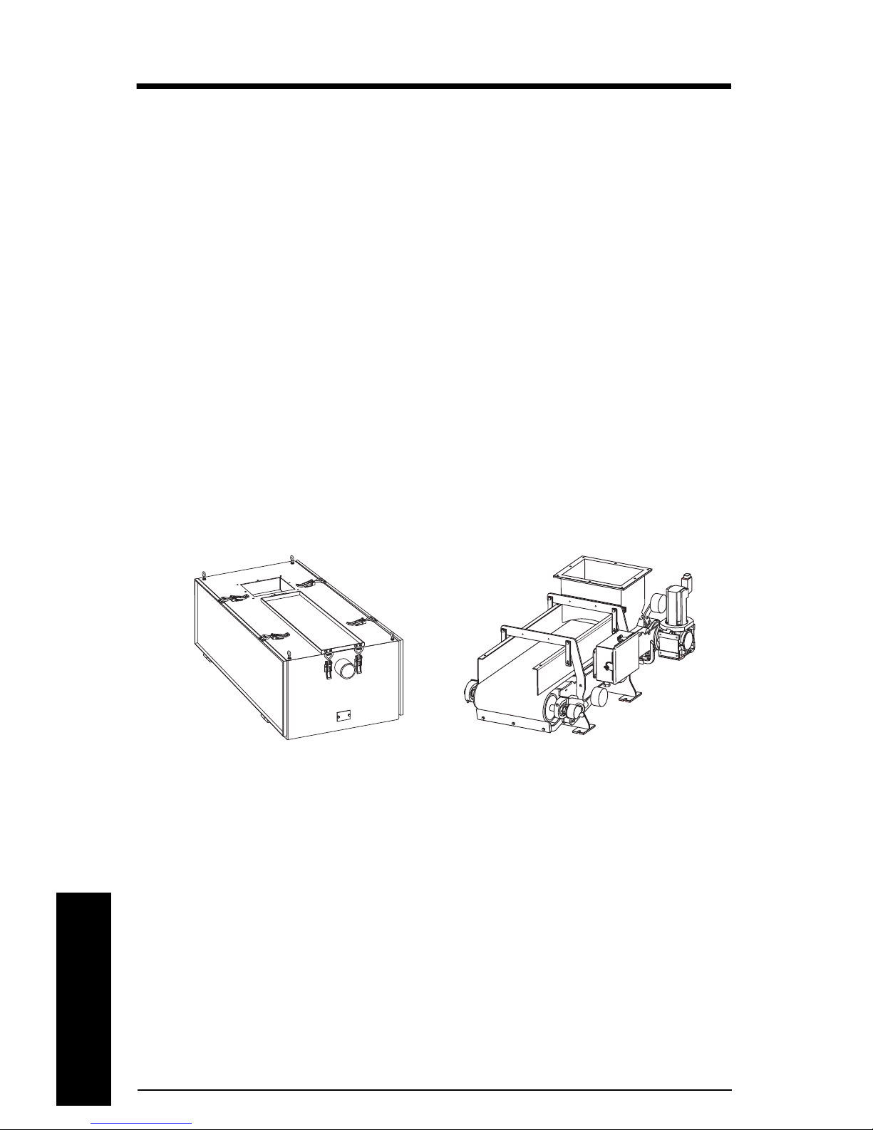
SITRANS WW100 is designed for assembly for both left and right side belt change. The
unit can be dis-assembled and re-assembled on the opposite side with the same
components.
Enclosed Open
mmmmm
Operation
Page 6 SITRANS WW100 - OPERATING INSTRUCTIONS 7ML19985MN01

Mechanical Installation
Installation
Perform a thorough and systematic inspection of shipping containers immediately upon
receipt of your Siemens weighfeeder. The shipping containers are packed to separate
each item and provide protection during shipping.
Note: Do not remove equipment from shipping crates or boxes until you check for
possible shipping damage. Contact the carrier immediately if damage is noted.
Your weighfeeder has been designed, assembled, and factory tested to ensure accuracy
and repeatability.
Notes:
• Refer to the mechanical drawings included with this manual prior to beginning
installation.
•Do NOT remove the tagged load cell shipping screw(s) until the installation is
complete to prevent load cell damage.
•Do NOT weld on or near the weighfeeder while the load cell is connected to the
electronic integrator. Damage to the integrator may result if the load cell is not
disconnected from the integrator.
• Follow a scheduled, preventative maintenance program to ensure optimum
performance and long equipment life.
mmmmm
Installation
Note: Only qualified personnel are authorized to install and operate this equipment.
Installation shall be in accordance with local regulations, standards and established
safety practices. Read and understand the instructions before installing, operating or
maintaining the equipment.
1. Align the in-feed section of the weighfeeder with the discharge of the feed device.
Prevent twisting or misalignment that could induce stress on the weighing section.
2. Install a gasket between the flanges for dust control.
3. Securely fasten the unit to a rigid, level structure. Use a level for verification and
shim as necessary. Prevent any twisting of the frame that may affect weighfeeder
performance.
4. Construct the necessary support framework to provide a sturdy, rigid base. Vibration
isolators are recommended if the location is subject to moderate or heavy vibration.
Note: Inlet and discharge will not support load.
5. Check the gear reducer oil level. See the gear reducer information in the appropriate
manual for further details on maintenance.
7ML19985MN01 SITRANS WW100 - OPERATING INSTRUCTIONS Page 7

6. Flexible in-feed connections are REQUIRED for all applications. Flexible discharge
connections are also recommended.
Note: A de-dust port is provided on enclosed units at the discharge end. Remove the
plastic insert and connect to system. If no de-dust system is required, do not remove
mmmmm
plastic insert.
Installation
7. Connect the electric supply to the motor and/or motor controller, following the
interwiring diagram supplied with this manual in the Appendix. The AC motor
controller must be grounded to minimize noise to the electronic integrator. Refer to
the applicable wiring diagram to make all electrical connections between the
electronic integrator and the weighfeeder.
Note: A termination box for the loadcells and speed sensor has been provided for
open units installed on the side frame of the unit, this can be removed and placed in
another location. Cable lengths are 9' (3 m) from the loadcell and speed sensor.
Enclosed units do not have a removable termination box.
8. Remove only the tagged shipping screw that is attached to the load cell. This screw
supports the weighbridge during transport and installation.
Notes:
• DO NOT loosen or tighten the overload bolt: it has been factory set to minimize the
possibility of load cell damage resulting from incidental overload.
• Units with a plugged discharge switch should refer to the wiring diagram included
in the CLS100 manual
9. Before starting the weighfeeder, make a final check to see that the conveyor belt is
free of all tools and foreign objects, and that the infeed/skirtboards are not pinching
against the belt.
Electrical installation
Notes:
• Refer to the electrical connection diagrams provided in the Appendix for several
different S110 connection scenerios, and for hand held controller (start, stop,
speed control, auto/man mode, and e-stop) connection.
• The communication cable (green) and power cable (orange) must connect the
servo motor to the S110 to operate.
If the emergency stop is independent from the integrated safety
feature on the control unit, wire or jumper the digital inputs to
complete the circuit. See connection diagrams provided in the
Appendix.
Page 8 SITRANS WW100 - OPERATING INSTRUCTIONS 7ML19985MN01
Initial S110 setup
1
2
3
4
The WW100 is configured with a Sinamics S110 CU305DP control and power module.
1. Ensure the electrical connections match the connection diagrams in the Appendix.
2. Apply power to the power module and allow boot sequence to run. The steady
green LED next to RDY on the unit indicates that the boot sequence is complete.
Notes:
• Do not continue until the boot sequence is complete.
• If the drive is in alarm state, refer to the S110 user manuals and/or contact your
Siemens representative.
3. Remove the power and ensure all power sources to the drive are switched OFF.
4. Insert the pre-programmed Micro Memory Card (MMC) into the slot below the S110
display and ensure the card locks into place.
5. Apply main AC power and then 24 Volt DC power to the device and allow the
application software to load.
Do not use P977 until software has loaded and parameters have
been set.
Failure to allow the software to load completely can result in lost
and irretrievable software and application data.
Installation
mmmmm
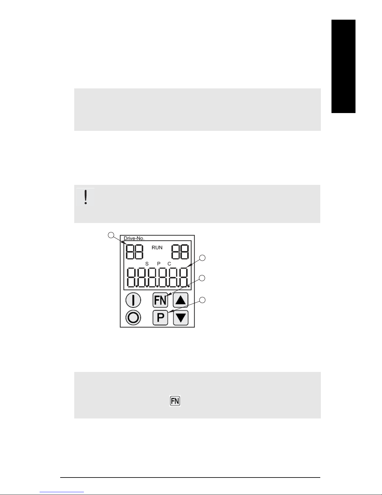
S110 Display
1.Drive number: there are two drive
data sets, each with their own set of
parameters.
01 = Command Data Set
02 = Drive Data Set
2.Parameter/value
RUN mode
EDIT mode
3.Function key
4.Parameter key
6. The S110 display will show "0.0" in the parameter/value field (2) when the software is
finished loading
and fault F01650 has been acknowledged.
Notes:
• Do not continue until the software is loaded.
• To acknowledge fault, press key (3) on display. (For more fault codes, see the
S110 user manuals and/or contact your Siemens representative).
7. Test the functionality of drive
8. Set the maximum RPM P2000 (see
9. Verify RPM output on display.
7ML19985MN01 SITRANS WW100 - OPERATING INSTRUCTIONS Page 9
a.If belt is travelling in reverse, set P1113 to either "0" or "1" (see
direction on page 10
P1113 - Belt
).
P2000 - Maximum RPM on page 11
).
 Loading...