

Siemens SITRANS WM300 MFA Operating Instructions Manual

___________________
___________________
___________________
___________________
___________________
___________________
___________________
___________________
___________________
___________________
___________________
___________________
SITRANS
Motion Sensors
SITRANS WM300 MFA
Operating Instructions
7MH77-.....(WM300 MFA)
08/2018
A5E45090709
Introduction
1
SITRANS WM300 MFA
Overview
2
Installing/mounting
3
Connecting
4
Service and maintenance
5
Parameter assignment
6
Troubleshooting
7
Technical data
8
Dimension drawings
9
Technical Reference
A
Applications
B
Support
C
-AA

Siemens AG
Division Process Industries and Drives
Postfach 48 48
90026 NÜRNBERG
GERMANY
Document order number: A5E45090709
Ⓟ
Copyright © Siemens AG 2018.
All rights reserved
Legal information
Warning notice system
DANGER
indicates that death or severe personal injury will result if proper precautions are not taken.
WARNING
indicates that death or severe personal injury may result if proper precautions are not taken.
CAUTION
indicates that minor personal injury can result if proper precautions are not taken.
NOTICE
indicates that property damage can result if proper precautions are not taken.
Qualified Personn el
personnel qualified
Proper use of Siemens products
WARNING
Siemens products may only be used for the applications described in the catalog and in the relevant technical
ambient conditions must be complied with. The information in the relevant documentation must be observed.
Trademarks
Disclaimer of Liability
This manual contains notices you have to observe in order to ensure your personal safety, as well as to prevent
damage to property. The notices referring to your personal safety are highlighted in the manual by a safety alert
symbol, notices referring only to property damage have no safety alert symbol. These notices shown below are
graded according to the degree of danger.
If more than one degree of danger is present, the warning notice representing the highest degree of danger will
be used. A notice warning of injury to persons with a safety alert symbol may also include a warning relating to
property damage.
The product/system described in this documentation may be operated only by
task in accordance with the relevant documentation, in particular its warning notices and safety instructions.
Qualified personnel are those who, based on their training and experience, are capable of identifying risks and
avoiding potential hazards when working with these products/systems.
Note the following:
documentation. If products and components from other manufacturers are used, these must be recommended
or approved by Siemens. Proper transport, storage, installation, assembly, commissioning, operation and
maintenance are required to ensure that the products operate safely and without any problems. The permissible
All names identified by ® are registered trademarks of Siemens AG. The remaining trademarks in this publication
may be trademarks whose use by third parties for their own purposes could violate the rights of the owner.
We have reviewed the contents of this publication to ensure consistency with the hardware and software
described. Since variance cannot be precluded entirely, we cannot guarantee full consistency. However, the
information in this publication is reviewed regularly and any necessary corrections are included in subsequent
editions.
for the specific
02/2019 Subject to change

Table of contents
1 Introduction ............................................................................................................................................. 7
2 SITRANS WM300 MFA Overview ........................................................................................................... 9
3 Installing/mounting ................................................................................................................................ 11
4 Connecting ........................................................................................................................................... 19
5 Service and maintenance ...................................................................................................................... 29
6 Parameter assignment .......................................................................................................................... 31
1.1 Purpose of this documentation ................................................................................................. 7
1.2 Document history ...................................................................................................................... 7
1.3 FW revision history ................................................................................................................... 7
1.4 Checking the consignment ....................................................................................................... 8
1.5 Unit repair and excluded liability ............................................................................................... 8
3.1 Safety Note ............................................................................................................................. 11
3.2 Location Requirements ........................................................................................................... 11
3.3 Proper Mounting ..................................................................................................................... 12
3.4 Mounting Details ..................................................................................................................... 13
3.5 Wiring ...................................................................................................................................... 16
4.1 Interconnection ....................................................................................................................... 19
4.1.1 MSP-3 or MSP-9 Probe with RMA (remote mounted amplifier) ............................................. 19
4.1.2 MSP-12 Probe with RMA (internally mounted pre-amplifier) .................................................. 20
4.1.3 XPP-5 with RMA (internally mounted pre-amplifier) ............................................................... 21
4.1.4 MSP-7 with IMA (internally mounted pre-amplifier) ................................................................ 22
4.1.5 Cable length from RMA or IMA to WM300 MFA ..................................................................... 23
4.1.6 Interconnection Diagram for XPP-5 ........................................................................................ 24
4.2 Connection to Power............................................................................................................... 26
5.1 Setup ....................................................................................................................................... 29
5.1.1 Calibration ............................................................................................................................... 29
5.2 Maintenance ........................................................................................................................... 29
6.1 Menu structure ........................................................................................................................ 31
6.2 Motion failure alarm ................................................................................................................ 32
6.3 Startup delay ........................................................................................................................... 34
6.3.1 Start up delay (P001) .............................................................................................................. 34
6.3.2 Start up delay (P002) .............................................................................................................. 35
6.4 Alarm delay ............................................................................................................................. 36
6.4.1 Alarm delay (P003) ................................................................................................................. 36
6.4.2 Alarm delay (P004) ................................................................................................................. 37
SITRANS WM300 MFA
Operating Instructions, 08/2018, A5E45090709-AA
3

Table of contents
7 Troubleshooting .................................................................................................................................... 53
8 Technical data ...................................................................................................................................... 55
9 Dimension drawings .............................................................................................................................. 59
A Technical Reference ............................................................................................................................. 67
B Applications .......................................................................................................................................... 71
6.5 Slow speed ............................................................................................................................. 38
6.5.1 Slow speed (P005) ................................................................................................................. 38
6.5.2 Slow speed (P010) ................................................................................................................. 38
6.5.3 Slow speed (P011) ................................................................................................................. 39
6.5.4 Slow speed (P012) ................................................................................................................. 40
6.5.5 Slow speed (P013) ................................................................................................................. 41
6.5.6 Process variable overview displ ay ......................................................................................... 42
6.5.7 Standard version motion failure alarm ................................................................................... 43
6.5.7.1 Standard speed (P020 - P021) .............................................................................................. 43
6.5.7.2 Standard speed (P022 - P023) .............................................................................................. 44
6.6 Tachometer Function ............................................................................................................. 45
6.6.1 Tachometer Function (P031 - P032) ..................................................................................... 45
6.6.2 Non-contacting tachometer (P030) ........................................................................................ 46
6.7 Differential speed detection ................................................................................................... 46
6.7.1 Differential speed detection (P040)........................................................................................ 46
6.7.2 Maximum frequency setpoint (P041 - P042) ......................................................................... 47
6.7.3 Differential alarm setpoints (P043 - P044) ............................................................................. 49
6.7.4 Operator display ..................................................................................................................... 50
7.1 Troubleshooting ..................................................................................................................... 53
8.1 Safety Note ............................................................................................................................ 55
8.2 Power ..................................................................................................................................... 55
8.3 Outputs ................................................................................................................................... 55
8.4 Inputs ..................................................................................................................................... 56
8.5 Performance ........................................................................................................................... 56
8.6 Design .................................................................................................................................... 57
8.7 Approvals ............................................................................................................................... 57
8.8 Operating Conditions ............................................................................................................. 57
9.1 SITRANS WM300 MFA dimensions ...................................................................................... 59
9.2 High Temperature Probe MSP-3 ........................................................................................... 61
9.3 Stainless Steel Probe MSP-9 ................................................................................................. 62
9.4 Standard Probe MSP-12 and MSP-7 ..................................................................................... 63
9.5 Hazardous Locations XPP-5 .................................................................................................. 64
A.1 Principles of Operation ........................................................................................................... 67
B.1 Bucket Elevators .................................................................................................................... 71
B.2 Bucket Elevator ...................................................................................................................... 72
SITRANS WM300 MFA
4 Operating Instructions, 08/2018, A5E45090709-AA

Table of contents
C Support ................................................................................................................................................. 79
Index..................................................................................................................................................... 81
B.3 Shafts ...................................................................................................................................... 73
B.4 Rotating Shaft of Rotary Feeder ............................................................................................. 74
B.5 Drive Sprocket on Rotary Feeder ........................................................................................... 74
B.6 Belt Conveyors ........................................................................................................................ 75
B.7 Screw Conveyors .................................................................................................................... 75
B.8 Screw Conveyor Flights .......................................................................................................... 76
B.9 End Bearing on Screw Conveyor ............................................................................................ 76
B.10 Non-ferrous Window ............................................................................................................... 77
C.1 Technical support .................................................................................................................... 79
C.2 Certificates .............................................................................................................................. 79
SITRANS WM300 MFA
Operating Instructions, 08/2018, A5E45090709-AA
5

Table of contents
SITRANS WM300 MFA
6 Operating Instructions, 08/2018, A5E45090709-AA

1
1.1
Purpose of this documentation
1.2
Document history
Edition
Note
1.3
FW revision history
Firmware revision
Date
Changes
These instructions are a brief summary of important features, functions and safety
information, and contain all information required for safe use of the device. Read the
instructions carefully prior to installation and commissioning. In order to use the device
correctly, first review its principle of operation.
The instructions are aimed at persons who install and commission the device.
To realize optimum performance from the device, read the complete operating instructions.
The following table shows major changes in the documentation compared to the previous
edition.
1/2019 First edition
1.00.00 January 1, 2019
• Initial release
SITRANS WM300 MFA
Operating Instructions, 08/2018, A5E45090709-AA
7
Introduction
1.4
Checking the consignment
WARNING
Using a damaged or incomp le te devic e
CAUTION
Insufficient protection during storage
1.5
Unit repair and excluded liability
Note
This product is intended for use in industrial areas.
In a domestic environment this device may cause radio interference.
1.4 Checking the consignment
1. Check the packaging and the delivered items for visible damages.
2. Report any claims for damages immediately to the shipping company.
3. Retain damaged parts for clarification.
4. Check the scope of delivery by comparing your order to the shipping documents for
correctness and completeness.
Risk of explosion in hazardous areas.
• Do not use damaged or incomplete devices.
To guarantee sufficient protection during transport and storage, observe the following:
● Keep the original packaging for subsequent transportation.
● Devices/replacement parts should be returned in their original packaging.
● If the original packaging is no longer available, ensure that all shipments are properly
packaged to provide sufficient protection during transport. Siemens cannot assume
liability for any costs associated with transportation damages.
The packaging only provides limited protection against moisture and infiltration.
• Provide additional packaging as necessary.
All changes and repairs must be done by qualified personnel, and applicable safety
regulations must be followed. Please note the following:
● The user is responsible for all changes and repairs made to the device.
● All new components must be provided by Siemens.
● Restrict repair to faulty components only.
● Do not re-use faulty components.
SITRANS WM300 MFA
8 Operating Instructions, 08/2018, A5E45090709-AA

2
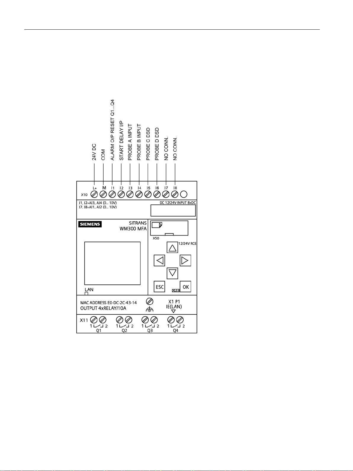
SITRANS WM300 MFA is a highly sensitive, dual setpoint motion sensor alarm unit, used
with MSP and XPP probes. The probe detects an increase or decrease in the speed of
rotating, reciprocating, or conveying equipment and sends the information to the SITRANS
WM300 MFA. The SITRANS WM300 MFA works with a pre-amplifier which can be internal
to the motion sensing probe or remote from the motion sensing probe.
Pulses generated from the probe are continually compared to the adjustable setpoint. If the
pulse rate is lower or higher than the setpoint, the alarm relays operating in a faiI-safe mode
will de-energize, indicating failure. The relays will not energize until the pulse rate increases
above or below the setpoint.
The relays can be reset automatically or manually. See Motion Failure Alarm (Page 32).
The SITRANS WM300 MFA is configured for a specific application and must be programmed
and hardwired according to application requirements. Unused inputs or outputs have no
effect on the devices specific operation and must not be wired to any other any other
peripheral equipment.
SITRANS WM300 MFA
Operating Instructions, 08/2018, A5E45090709-AA
9

SITRANS WM300 MFA Overview
SITRANS WM300 MFA
10 Operating Instructions, 08/2018, A5E45090709-AA
3
3.1
Safety Note
Note
Installation shall only be performed by qualified personnel and in accordance with local
governing regulations.
3.2
Location Requirements
The SITRANS WM300 MFA (and RMA or NCT and power supply converter if applicable)
must be mounted in a non-hazardous area that is clean, dry, vibration-free, within the
ambient temperature range, and non-corrosive to the electronics or its enclosure. The
cabinet door should be accessible for viewing and to allow calibration of the SITRANS
WM300 MFA.
Consider the probe location carefully before installation. Avoid strong magnetic fields
(50/60 Hz) from nearby power transformers, heater elements, or large industrial motors,
because these can affect the probe’s performance.
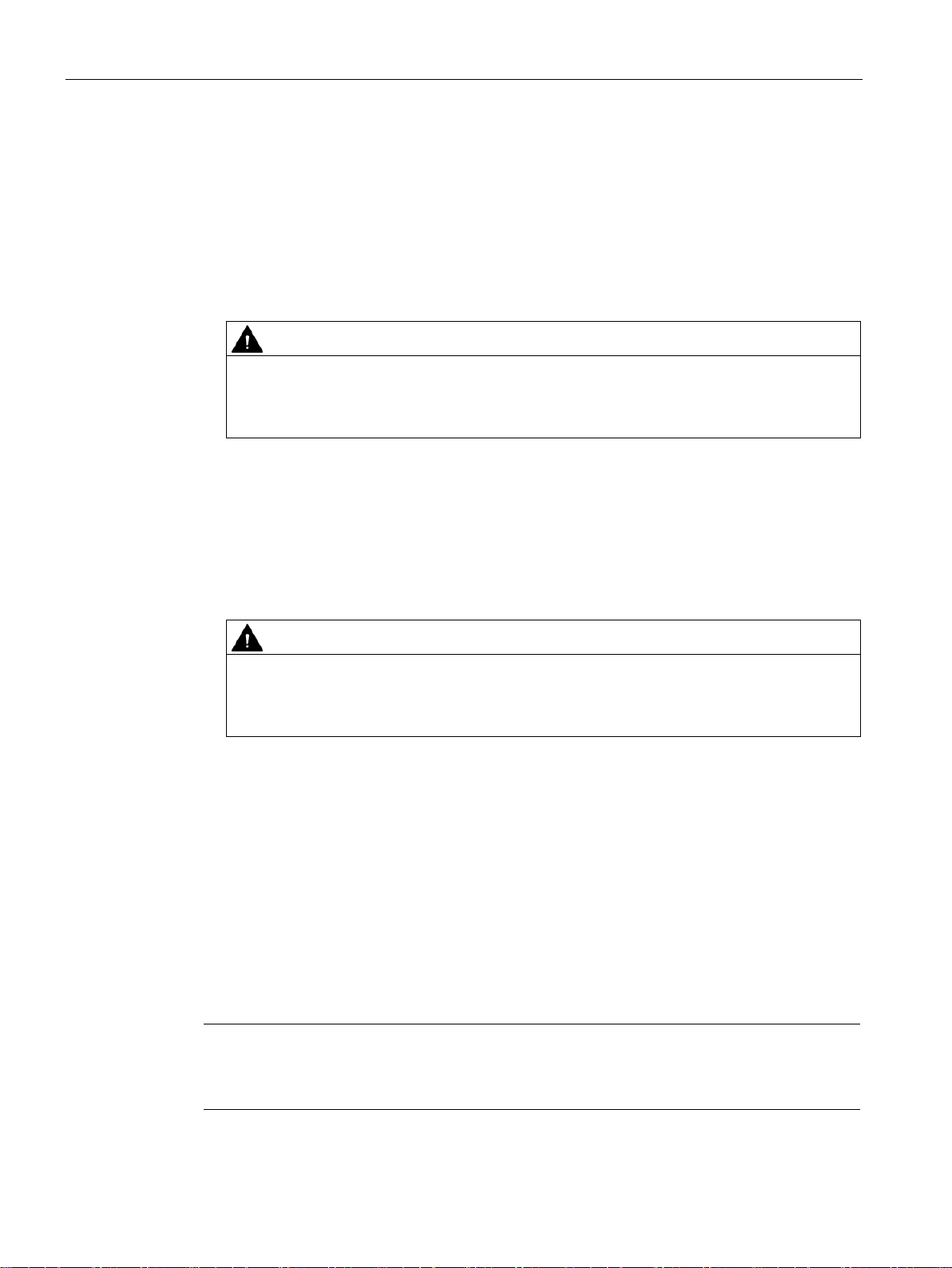
An additional remote display can be connected to the SITRANS WM300 MFA for access to
the unit within an enclosure.
SITRANS WM300 MFA
Operating Instructions, 08/2018, A5E45090709-AA
11

Installing/mounting
Note
Do not mount SITRANS WM300 MFA in direct sunlight.
3.3
Proper Mounting
Functionality loss indicators:
3.3 Proper Mounting
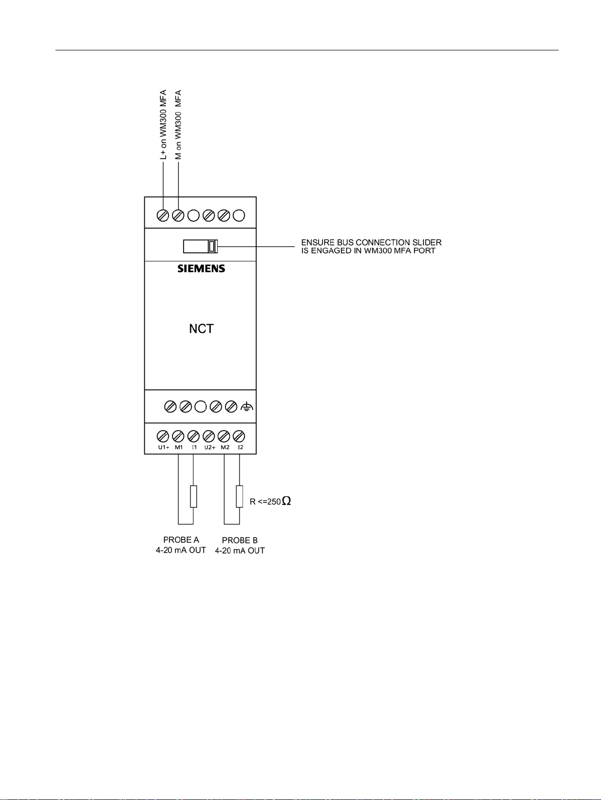
The SITRANS WM300 MFA can be DIN or wall mounted. In a stand-alone enclosure or
panel arrangement, the device can use a power transformer to take AC to DC voltage. An
additional NCT analog output module is necessary to be integrated into the SITRANS
WM300 MFA bus connection and additional RMA depending on the application
requirements.
The probe should be mounted onto a vibration free structure using the mounting flange. The
gap between probe and target should be large enough to prevent the target from damaging
the probe. The probe environment must be within the probe's ambient temperature range
and non-corrosive to the probe's body. Refer to Applications (Page 71).
The probe design detects a changing magnetic field, typically caused by a ferromagnetic
target disturbing the probe's magnetic field. Extremely strong magnetic fields (like those
produced by the 30 A/m requirements of 1EC 60004-8, Power Frequency Magnetic Field
Immunity test) will be detected and will result in loss of functionality.
● Alarm conditions by relay output
SITRANS WM300 MFA
12 Operating Instructions, 08/2018, A5E45090709-AA
Installing/mounting
3.4
Mounting Details
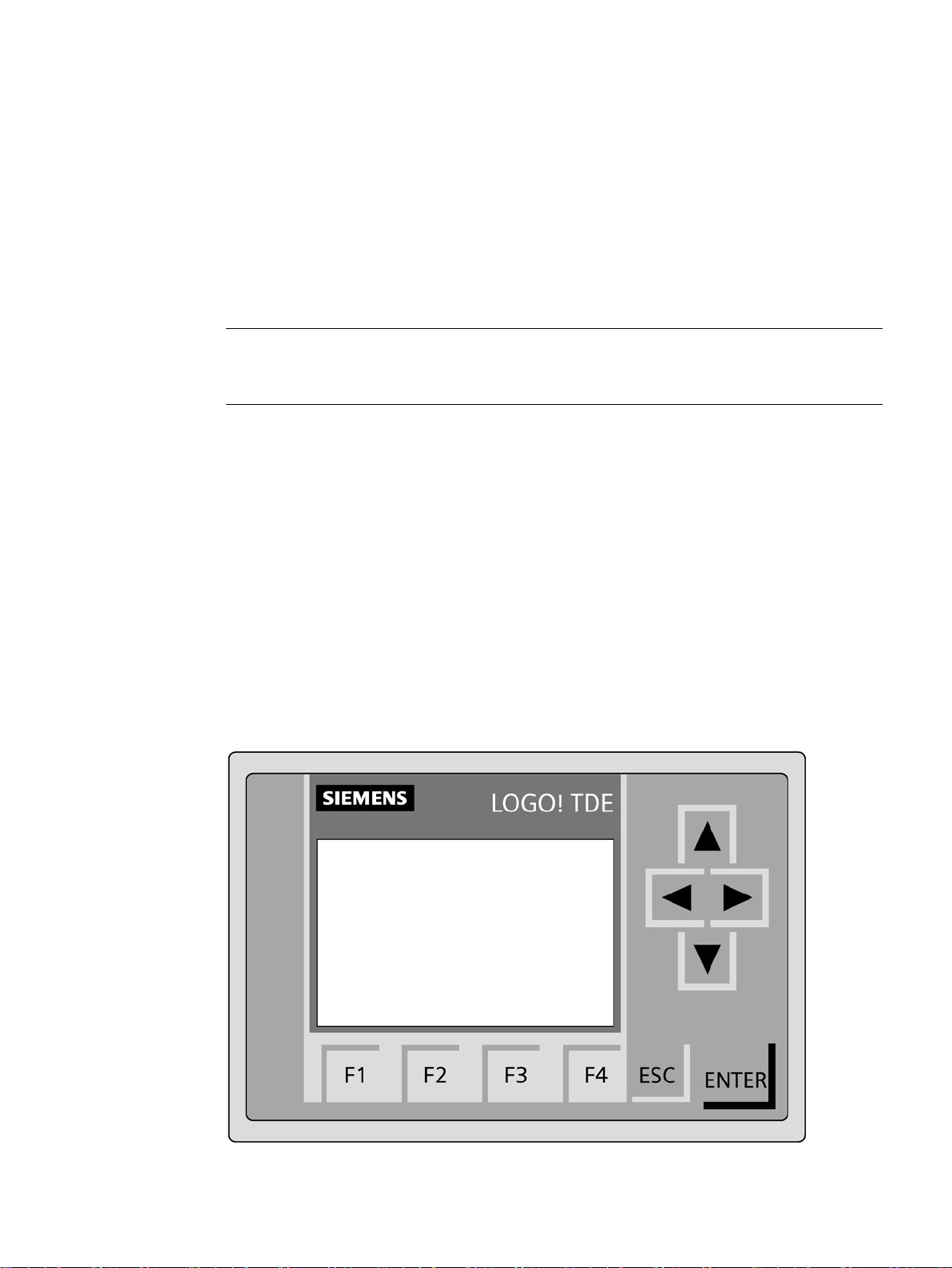
①
Mounting slide
3.4 Mounting Details
To mount the SITRANS WM300 MFA or other components, slide the DIN rail mounting clips
outside of the enclosure and to the mounting holes.
SITRANS WM300 MFA
Operating Instructions, 08/2018, A5E45090709-AA
13

Installing/mounting
For wall mounting slide the tabs out and mount to the wall/post with M4 screws.
①
Mounting slide
3.4 Mounting Details
SITRANS WM300 MFA
14 Operating Instructions, 08/2018, A5E45090709-AA
Installing/mounting
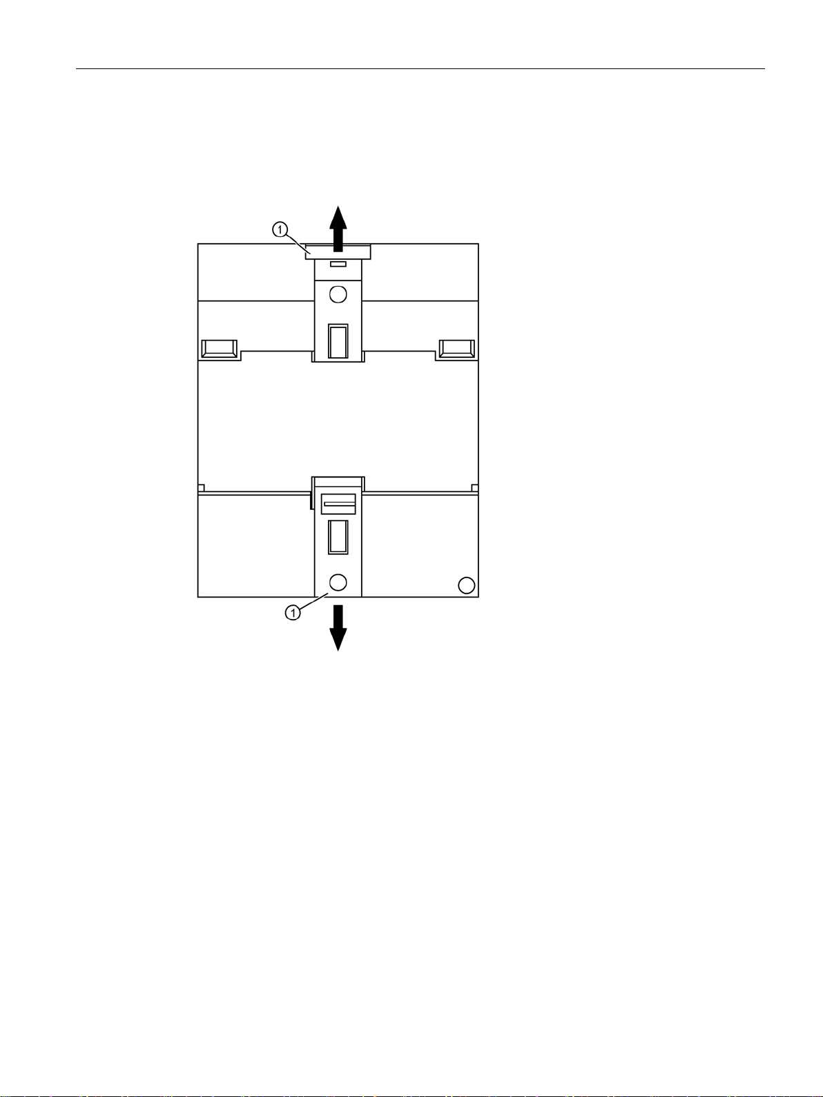
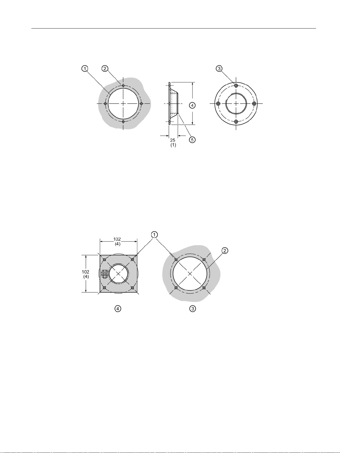
MSP-3, MSP-7, MSP-12, XP P-5 Mounting Details
MSP-9 Mounting Details
3.4 Mounting Details
Dimensions in mm (inch)
① 95 (3.75) ∅ probe clearance hole
② 6 (0.25) ∅ hole for ¼ - 20 nut and bolt or drill and tap, four holes on 114 (4.5) BCD
③ 6 (0.25) ∅ hole for ¼ - 20 bolt on 114 (4.5) BCD, four places
④ 113 (5.25) O.D.
⑤ 2" NSPL
Dimensions in mm (inch)
① 6 (0.25) ∅ 4 holes equally spaced on a 114 (4.5) BCD
② 95 (3.75) ∅ probe clearance hole
③ Panel cutout
④ Probe flange
● For high temperature and corrosion resistant applications
● 304 stainless steel body comes with stainless steel clamp and silicone gasket
SITRANS WM300 MFA
Operating Instructions, 08/2018, A5E45090709-AA
15
Installing/mounting
3.5
Wiring
3.5 Wiring
Where possible, the probe components should be interconnected via flexible conduit. This
allows for easier removal or adjustment of the probe and mounting flange assembly.
SITRANS WM300 MFA
16 Operating Instructions, 08/2018, A5E45090709-AA
Installing/mounting
3.5 Wiring
SITRANS WM300 MFA
Operating Instructions, 08/2018, A5E45090709-AA
17
Installing/mounting
Note
RMA not required for use with MSP
correct signal conditioning. Improper switch selection may damage the device.
3.5 Wiring
-7. Proper switch s elec t ion must be made to ens ure
SITRANS WM300 MFA
18 Operating Instructions, 08/2018, A5E45090709-AA
4
4.1
Interconnection
Note
Use
differential ground loops.
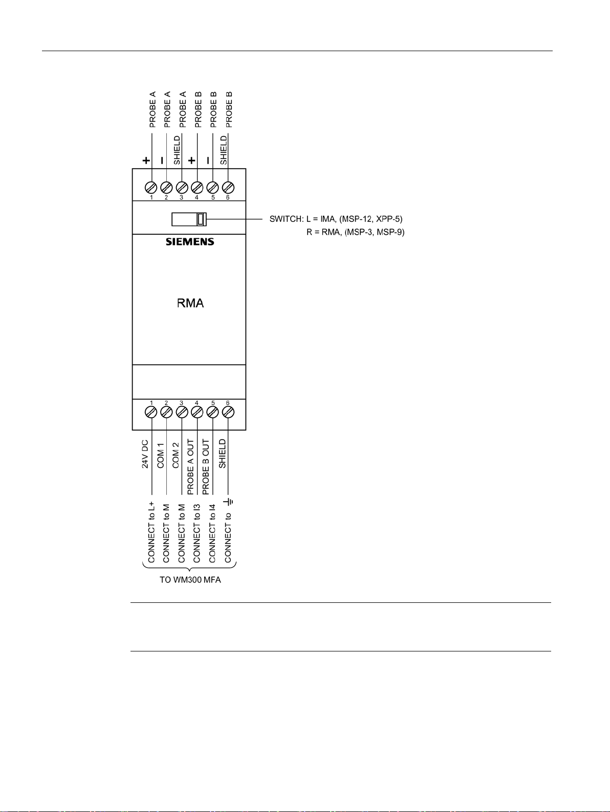
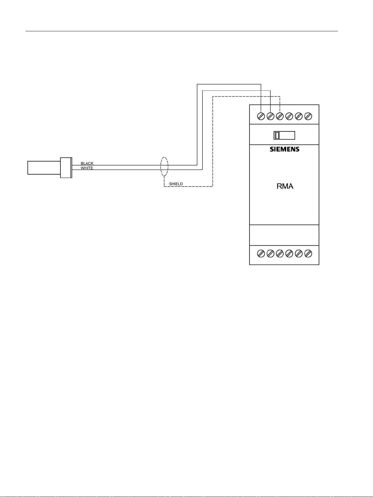
4.1.1
MSP-3 or MSP-9 Probe with RMA (remote mounted amplifier)
shielded cable and connect all cable shields to the MFA shield terminals to avoid
SITRANS WM300 MFA
Operating Instructions, 08/2018, A5E45090709-AA
● RMA selector switch to the right
● Maximum cable length from probe to RMA is 30 m/100 ft of shielded cable, 18 ga. wire.
● 1.5 m (5 ft) Belden 83321 Teflon
See Cable length from RMA or IMA to WM300 MFA (Page 23) for cable lengths from
RMA to main group.
1)
Teflon is a registered trademark of E.I. du Pont de Nemours and Company
1)
cable potted in probe
19
Connecting
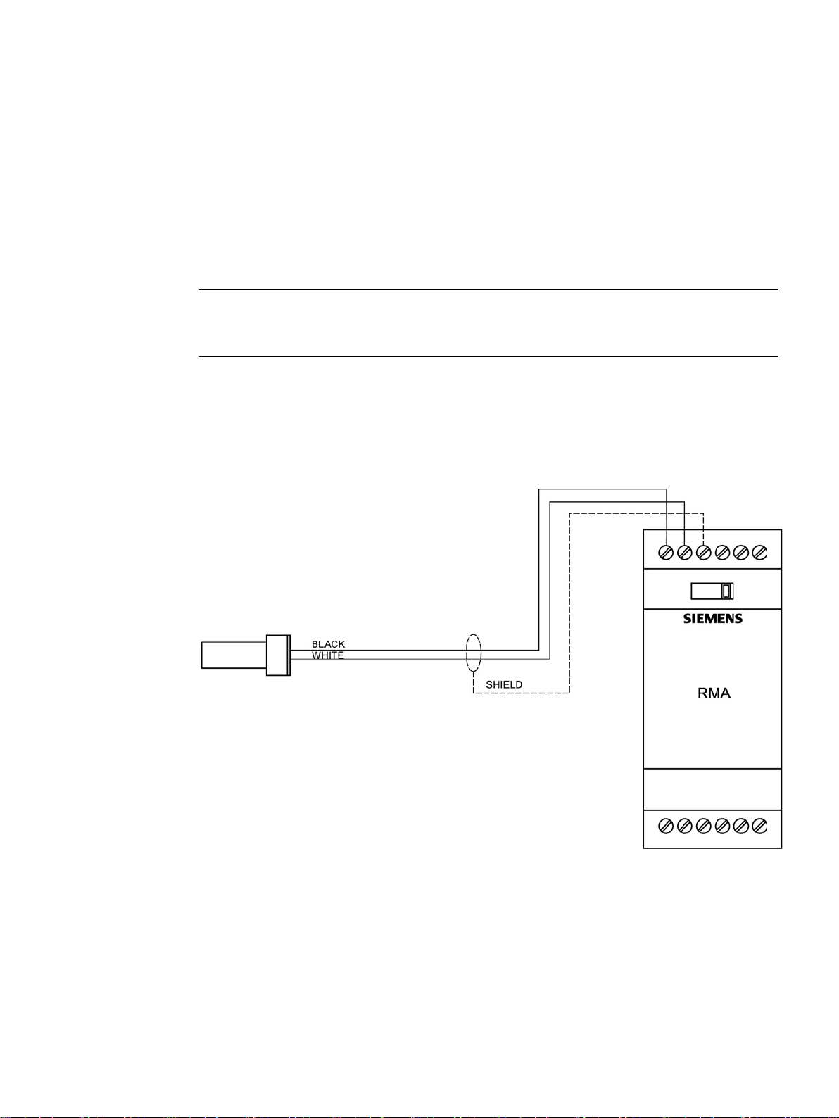
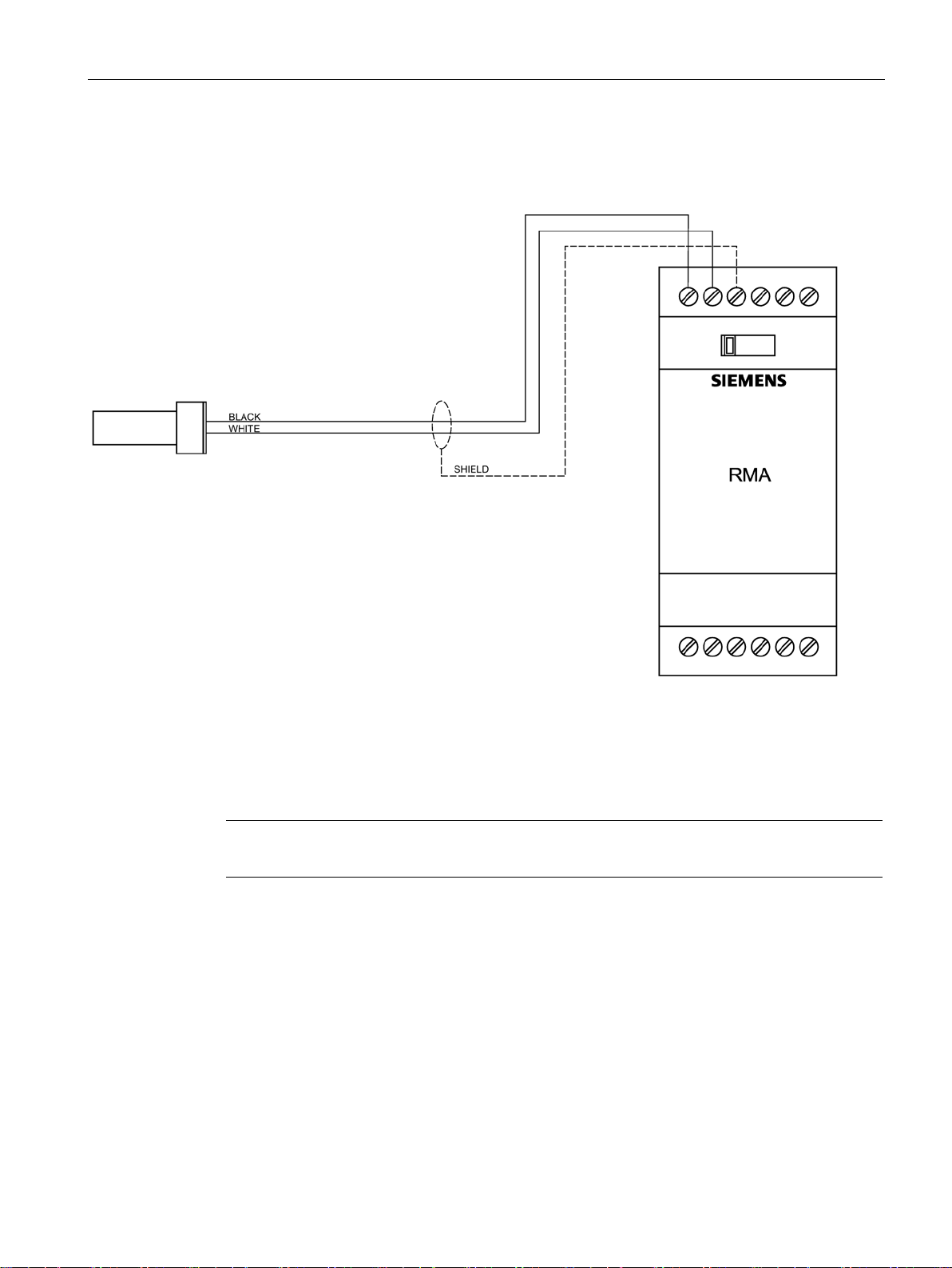
4.1.2
MSP-12 Probe with RMA (internally mounted pre-amplifier)
4.1 Interconnection
● RMA selector switch to the left.
● Wire can be run in conduit common to motor supply or control wiring. Connection to
probe terminals can be made under probe cap.
See cable lengths (Page 23)for maximum separation from probe to RMA.
SITRANS WM300 MFA
20 Operating Instructions, 08/2018, A5E45090709-AA
Connecting
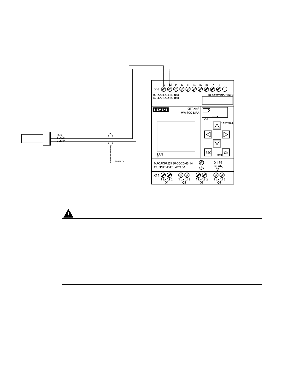
4.1.3
XPP-5 with RMA (internally mounted pre-amplifier)
Note
Refer to
4.1 Interconnection
● RMA selector switch to the left.
● XPP-5 cable must be run in dedicated, approved metal conduit, boxes and fittings and to
procedures in accordance with all governing regulations. See Cable length from RMA or
IMA to WM300 MFA (Page 23) for cable lengths from probe at SITRANS WM300 MFA.
See cable lengths for maximum separation from probe to RMA.
Interconnection Diagram for XPP-5 (Page 24)
SITRANS WM300 MFA
Operating Instructions, 08/2018, A5E45090709-AA
21
Connecting
4.1.4
MSP-7 with IMA (internally mounted pre-amplifier)
WARNING
Unsuitable cables, cable glands and/or plugs
4.1 Interconnection
Wire can be run in conduit. Connection to probe terminals can be made under probe cap.
See cable lengths (Page 23) for maximum separation from probe to SITRANS WM300 MFA.
Risk of explosion in hazardous areas.
• Use only cable glands/plugs that comply with the requirements for the relevant type of
protection.
• Tighten the cable glands in accordance with the torques specified in Cable length from
RMA or IMA to WM300 MFA (Page 23).
• Close unused cable inlets for the electrical connections.
• When replacing cable glands, only use cable glands of the same type.
• After installation, check that the cables are seated firmly.
SITRANS WM300 MFA
22 Operating Instructions, 08/2018, A5E45090709-AA

Connecting
WARNING
Incorrect conduit system
4.1.5
Cable length from RMA or IMA to WM300 MFA
Wire gauge
Length in feet
Length in meters
22 AWG (0.34 mm2)
2 500
760
18 AWG (0.75 mm2)
5 000
1 520
12 AWG (4 mm2)
25 000
7 600
4.1 Interconnection
Risk of explosion in hazardous areas as result of open cable inlet or incorrect conduit
system.
• In the case of a conduit system, mount a spark barrier at a defined distance from the
device input. Observe national regulations and the requirements stated in the relevant
approvals.
SITRANS WM300 MFA
Operating Instructions, 08/2018, A5E45090709-AA
23

Connecting
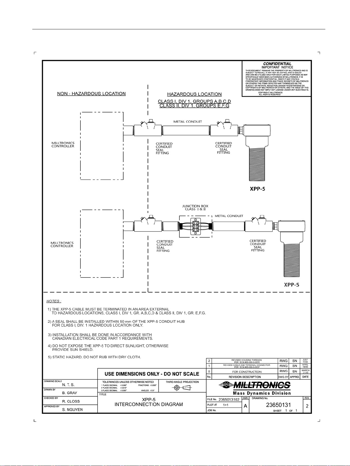
4.1.6
Interconnection Diagram for XPP-5
4.1 Interconnection
SITRANS WM300 MFA
24 Operating Instructions, 08/2018, A5E45090709-AA
Connecting
4.1 Interconnection
SITRANS WM300 MFA
Operating Instructions, 08/2018, A5E45090709-AA
25
 Loading...