

Siemens SITRANS WFS320 Operating Instructions Manual
Sensing Heads
SITRANS WFS320
Operating Instructions
Edition
02/2016

SITRANS
Sensing Heads
SITRANS WFS320
Operating Instructions
02/2016
A5E32880290
-AB
Introduction
1
Safety notes
2
Description
3
Installing/mounting
4
Connecting
5
Commissioning
6
Service and maintenance
7
Diagnosing and
troubleshooting
8
Technical Data
9
Dimension drawings
10
Appendix A
A

Siemens AG
Division Process Industries and Drives
Postfach 48 48
90026 NÜRNBERG
GERMANY
Document order number: A5E32880290
Ⓟ
03/2016 Subject to change
Copyright © Siemens AG 2014.
All rights reserved
Legal information
Warning notice system
This manual contains notices you have to observe in order to ensure your personal safety, as well as to prevent
damage to property. The notices ref er ring to your personal safety are highl ighted in the manual by a safety alert
symbol, notices referring only to property damage have no safety alert symbol. These notices shown below are
graded according to the degree of danger.
DANGER
indicates that death or severe pers onal injury will result if proper precaution s are not taken.
WARNING
indicates that death or severe pers onal injury may result if proper precautions are not taken.
CAUTION
indicates that minor personal inj ur y can result if proper precautions are not taken.
NOTICE
indicates that property damage can r es ult if proper precautions are not taken.
If more than one degree of danger is present, the warning notice representing the highest degree of danger will be
used. A notice warning of injury to persons with a safety alert symbol may als o i nc lude a warning relating to property
damage.
Qualified Personnel
The product/system described in this documentation may be operated on l y by
personnel qualified
for the specific task
in accordance with the relevant doc um entation, in particular its warning notices and safety instructions. Qualified
personnel are those who, based on thei r training and experience, are capable of identifying risks and avoiding
potential hazards when working with these products/systems.
Proper use of Siemens products
Note the following:
WARNING
Siemens products may only be used for the applications described in t he catalog and in the relevant tec hni cal
documentation. If products and components from other manufacturers ar e used, these must be recommended
or approved by Siemens. Proper tr ansport, storage, installation, as s embly, commissioning, operatio n and
maintenance are required to ensure that the products operate safely and without any problems. The permissible
ambient conditions must be complied with. The information in the relev ant documentation must be observed.
Trademarks
All names identified by ® are registered trademarks of Siemens AG. T he r emaining trademarks in this publication may
be trademarks whose use by third part i es for their own purposes could violate the rights of the owner.
Disclaimer of Liability
We have reviewed the contents of this publication to ensure consistency with the hardware and software desc ribed.
Since variance cannot be precluded entirely, we cannot guarantee full c onsistency. However, the information in this
publication is reviewed regula rly and any necessary corrections are i nc l uded in subsequent editions.

SITRANS WFS320
Operating Instructions, 02/2016, A5E32880290-AB
3
Table of contents
1 Introduction ................................................................................................................................................ 5
1.1 The manual ............................................................................................................................... 5
2 Safety notes ............................................................................................................................................... 7
2.1 General safety instructions ....................................................................................................... 7
2.2 Installation in hazardous areas ................................................................................................. 7
3 Description ............................................................................................................................................... 11
3.1 SITRANS WFS320 ................................................................................................................. 11
3.2 Principle of operation .............................................................................................................. 11
4 Installing/mounting ................................................................................................................................... 13
4.1 Sensing head .......................................................................................................................... 13
4.2 Sensing plate .......................................................................................................................... 14
4.3 Viscous damper ...................................................................................................................... 15
5 Connecting .............................................................................................................................................. 17
5.1 Unit without LVDT conditioner card ........................................................................................ 17
5.2 Unit with sensing head mounted LVDT conditioner card........................................................ 18
5.3 Unit with remote-located LVDT conditioner card .................................................................... 20
6 Commissioning ........................................................................................................................................ 25
6.1 Calibration ............................................................................................................................... 25
6.2 LVDT Output ........................................................................................................................... 26
6.3 Span test ................................................................................................................................. 27
6.4 Sensing head level test ........................................................................................................... 27
6.5 Integrator calibration ............................................................................................................... 28
6.6 Zero calibration ....................................................................................................................... 28
6.7 Span calibration ...................................................................................................................... 28
7 Service and maintenance ........................................................................................................................ 31
7.1 Maintenance ........................................................................................................................... 31
7.2 Spare parts ............................................................................................................................. 31
7.3 Inner gasket replacement ....................................................................................................... 32
7.4 Technical support .................................................................................................................... 32
8 Diagnosing and troubleshooting .............................................................................................................. 35
8.1 Range springs ......................................................................................................................... 35

Table of contents
SITRANS WFS320
4 Operating Instructions, 02/2016, A5E32880290-AB
8.2 Troubleshooting ..................................................................................................................... 36
8.3 Linearity .................................................................................................................................. 36
9 Technical Data ......................................................................................................................................... 39
9.1 Performance ........................................................................................................................... 39
9.2 Construction ........................................................................................................................... 39
9.3 Input ....................................................................................................................................... 40
9.4 Output .................................................................................................................................... 40
9.5 Operating conditions .............................................................................................................. 40
9.6 Approvals ............................................................................................................................... 41
10 Dimension drawings ................................................................................................................................ 43
10.1 WFS320 sensing head outline and mounting ........................................................................ 43
A Appendix A .............................................................................................................................................. 45
A.1 WFS320 part identification diagram ....................................................................................... 45

SITRANS WFS320
Operating Instructions, 02/2016, A5E32880290-AB
5
1
Note
The SITRANS sensing head is to be used only in the manner outlined in this manual,
otherwise protection provided by equipment m ay be impaired.
•
It is your responsibility to read this manual before installing and starting up any
component of the weighing system to which the sen sing head is being applied.
Note
For industrial use only
This product is intended for use in industrial areas. Operation of this equipme
nt in a
residential area may cause interference to several frequency based communications.
1.1
The manual
This manual covers only sensing head installatio n, operation, and maintenance procedures.
Flowmeter and integrator instruction manuals a re available for download from our web site:
Siemens weighing (http://www.siemens.com/weighing)
Follow these operating instructions for quick, trouble-free installation, and maximum accu racy
and reliability of your device.
We always welcome suggestions and comment s about manual content, design, and
accessibility. Please direct your comments to:
Technical publications (mailto:techpubs.smpi@siemens.com)

Introduction
1.1 The manual
SITRANS WFS320
6 Operating Instructions, 02/2016, A5E32880290-AB

SITRANS WFS320
Operating Instructions, 02/2016, A5E32880290-AB
7
2
2.1
General safety instructions
CAUTION
Correct, reliable operation of the product requi res proper transport, storage, positioning and
assembly as well as careful operation and maintenance. Only qualified personnel should
install or operate this instrument.
Note
Alterations to the product, including opening or im proper repairs of the product, are not
permitted.
If this requirement is not observed, the CE mark and t he m anuf acturer's warranty will expire.
2.2
Installation in hazardous areas
WARNING
Equipment used in hazardous areas must be Ex-approved and marked accordingly. It is
required that the special conditions for safe use provided in the manual and in the Ex
certificate are followed.
Safety notes
2.2 Installation in hazardous areas
SITRANS WFS320
8 Operating Instructions, 02/2016, A5E32880290-AB
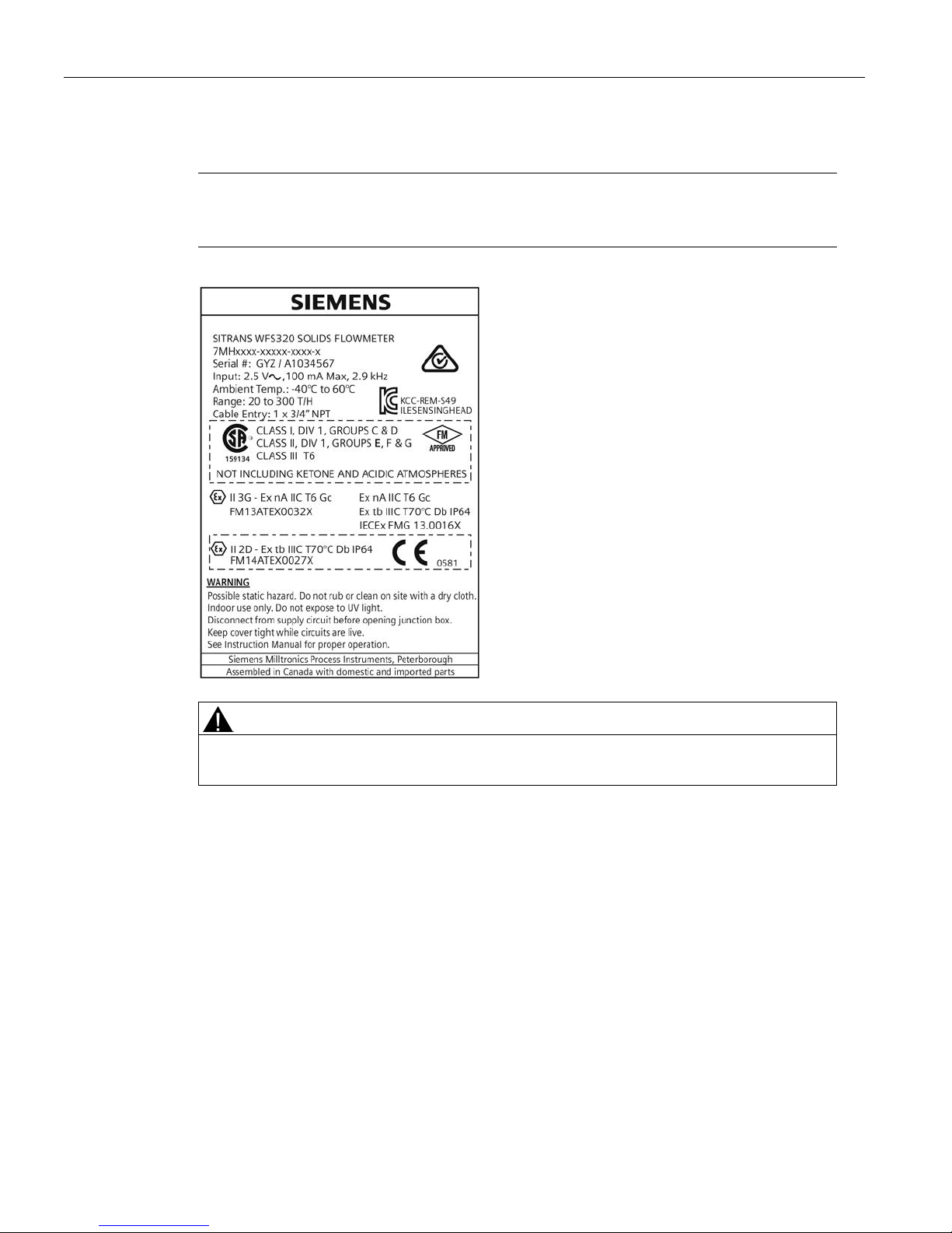
WFS320 nameplate
Note
The nameplate shown is a typical example. Please check the nameplate on your device for
your specific device configuration.
WARNING
Make sure the hazardous area approval is suitable f or the environment in which the device
will be installed.
Instructions specific to hazardous area installations
(Reference European ATEX Directive 94/9/EC, Annex II, 1/0/6)
The following instructions apply to equipment cove red by certificate number FM13ATEX0032X,
or certificate number FM14ATEX0027X, or both if neither certificate is specified.
1. For use and assembly, refer to the main instruction s.
2. The equipment is certified for use as Category 3G equipm ent per FM13ATEX0032X.
3. Per FM13ATEX0032X, the equipment may be used with fl am m able gases and vapours with
apparatus group IIA, IIB, and IIC, and temperature classes T1, T2, T3, T4, T5, and T6 in zone
2 hazardous locations.
4. The equipment is certified for use as Category 2D equipment per FM14ATEX0027X.

Safety notes
2.2 Installation in hazardous areas
SITRANS WFS320
Operating Instructions, 02/2016, A5E32880290-AB
9
5. Per FM14ATEX0027X, the equipment has a degree of i ngress protection of IP64 and a
temperature class of T70ºC and may be used with flam m able, conductive dusts in zone 21
and 22 hazardous locations.
6. The equipment is certified for use in an ambient temperature range of -40ºC to +60ºC.
7. The equipment has not been assessed as a safety rel ated device (as referred to by Directive
94/9/EC Annex II, clause 1.5).
8. Installation and inspection of the equipment shall be carried out by suitably trained personnel
in accordance with the applicable code of practice.
9. Repair of the equipment shall be carried out by suitably trained personnel in accordance with
the applicable code of practice.
10. Components to be incorporated into or used as replacements in the equipment shall be fitted
by suitably trained personnel in accordance with the m anufacturer’s documentation.
11. Each certificate number has an ‘X’ suffix, which indicates that speci al conditions for safe use
apply. Those installing or inspecting the equipment must have access to the certificates.
12. If the equipment is likely to come into contact with aggressive substances, then it is the
responsibility of the user to take suitable precautions that prevent it from being adversely
affected, thus ensuring that the type of protection is not compromised.
– Aggressive substances:
for example, acidic liquids or gases that may attack metals, or solvents that may affect
polymeric materials.
– Suitable precautions:
for example, establishing from the material’s dat a sheet that it is resistant to specific
chemicals.
Special conditions for safe use
Certificate number FM13ATEX0032X
The ‘X’ suffix to certificate number FM13ATEX0032X relates to the following special conditions
for safe use:
● The enclosure is non-conducting and, under certain extreme conditions, may generate an
ignition-capable level of electrostatic charges. The user shall ensure that the equipment is not
installed in a location where it may be subjected to ext ernal conditions (such as high-pressure
steam) which might cause a build-up of electrostati c c harges on non-conducting surfaces.
Additionally, cleaning of the equipment should be done only with a damp cloth.
● Indoor use only. Additionally, the user shall ensure that the equipment is not installed in a
location where it is continuously exposed to ultraviolet light.
Certificate number FM14ATEX0027X
The ‘X’ suffix to certificate number FM14ATEX 0027X relates to the following special conditions
for safe use:
● The enclosure is non-conducting and, under certain extreme conditions, may generate an
ignition-capable level of electrostatic charges. The user shall ensure that the equipment is not
installed in a location where it may be subjected to ext ernal conditions (such as high-pressure

Safety notes
2.2 Installation in hazardous areas
SITRANS WFS320
10 Operating Instructions, 02/2016, A5E32880290-AB
steam) which might cause a build-up of electrostati c c harges on non-conducting surfaces.
Additionally, cleaning of the equipment should be done only with a damp cloth.
● Indoor use only. Additionally, the user shall ensure that the equipment is not installed in a
location where it is continuously exposed to ultraviolet light.
● Magnesium, titanium or zirconium may be used at the accessibl e surface of the equipment. In
the event of rare incidents, ignition sources due to impact and friction sparks could occur.
This shall be considered when the WFS320 is being inst all ed in locations that specifically
require Equipment Protection Level Db.
SITRANS WFS320
Operating Instructions, 02/2016, A5E32880290-AB
11
3
3.1
SITRANS WFS320
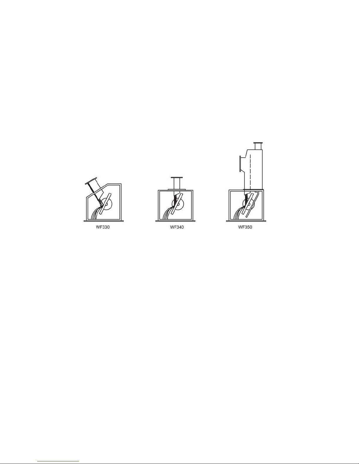
SITRANS WFS320 sensing head is an out-of-pro cess sensing element used for continuous inline weighing of powdered or granular dry bulk solid materials. It is used with the 300 tph
versions of SITRANS WF330 (general purpose), WF340 (vertical material drop), and WF350
(aerated gravity conveyor) dry solids flowmeters.
3.2
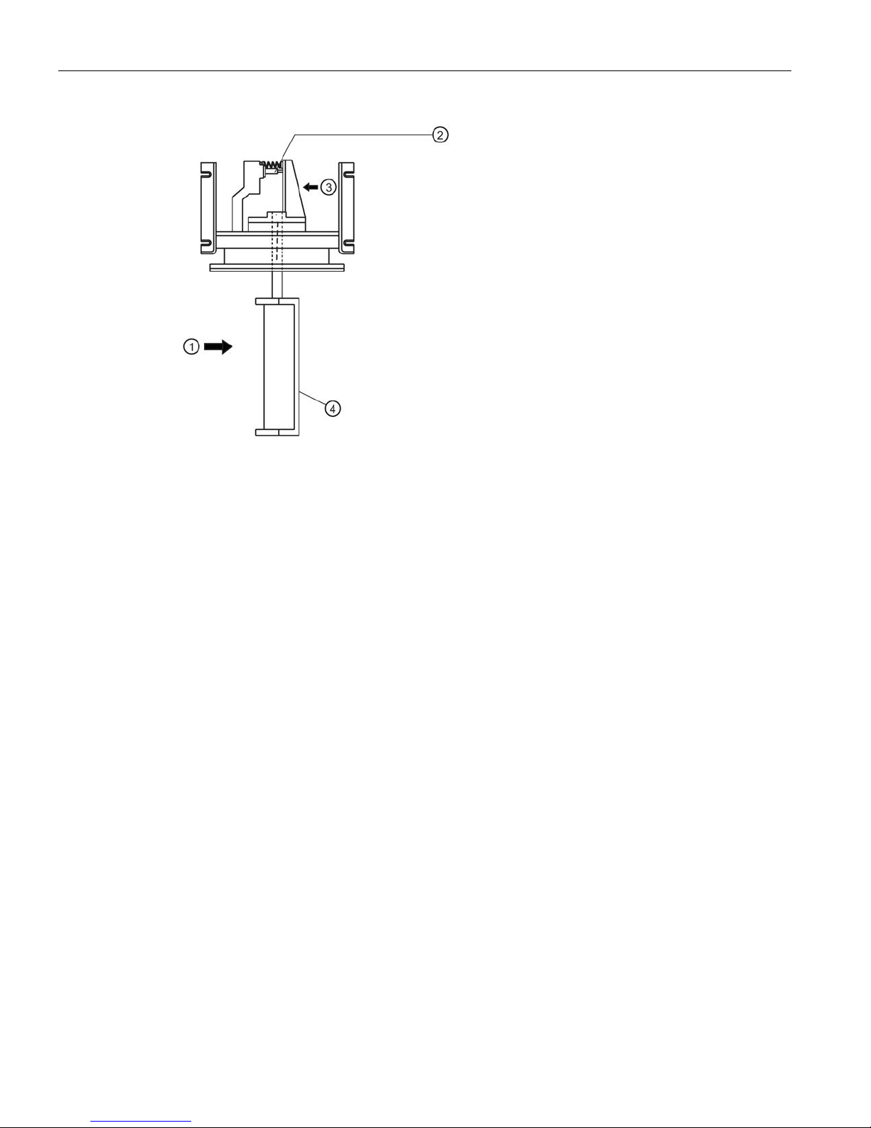
Principle of operation
SITRANS sensing heads are used for continuous weighing of dry bulk solid materials. The
material is directed toward the sensing plate. The horizontal impact force of the material deflects
the sensing plate, displacing the core of the sensi ng head LVDT (linear variable differential
transformer). The LVDT produces an output signal which is proportional to material flowrate. A
viscous fluid damper prevents oscillation of the mechanism and provides mechanical damping of
pulsating material flow.
Description
3.2 Principle of operation
SITRANS WFS320
12 Operating Instructions, 02/2016, A5E32880290-AB
①
Impact force
③
Moving beam travel
②
LVDT
④
Sensing plate
SITRANS WFS320
Operating Instructions, 02/2016, A5E32880290-AB
13
4
CAUTION
Installation shall be performed only by qualifi ed personnel in accordance with local
governing regulations.
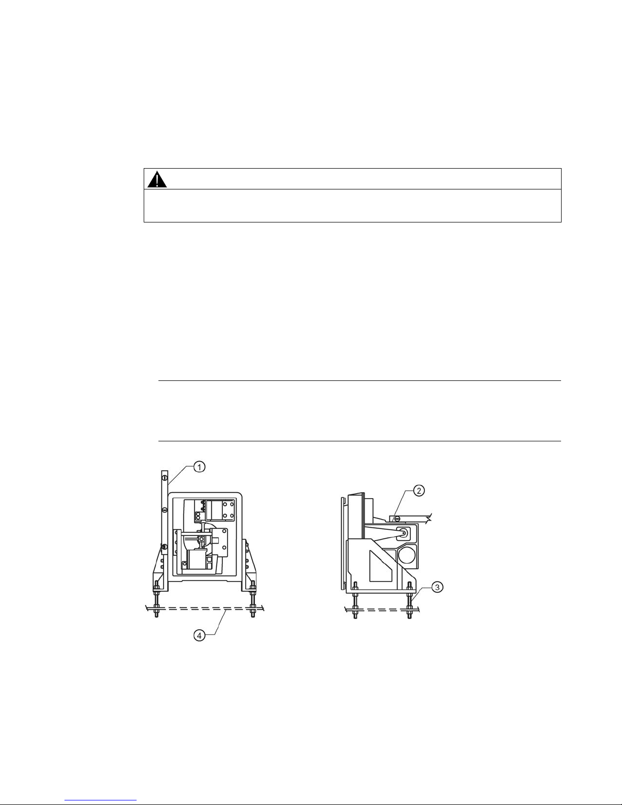
4.1
Sensing head
1. With the flowmeter housing installed, mount the sensing head to a rigid support structure.
2. Remove the sensing head fiberglass cover. Wit h the outer gasket in place, bolt the sensing
head to the housing.
3. Adjust the sensing head levelling hardware (provid ed) to establish level in both horizontal
planes.
Note
Ensure that the structure used to s
upport the base mount sensing head is capable of
supporting the dynamic material impact forces as well as the static weight of the sensing
head.
①
Spirit level
③
Supporting/levelling bolts
②
Moving beam (machined surface)
④
Rigid support
Installing/mounting
4.2 Sensing plate
SITRANS WFS320
14 Operating Instructions, 02/2016, A5E32880290-AB
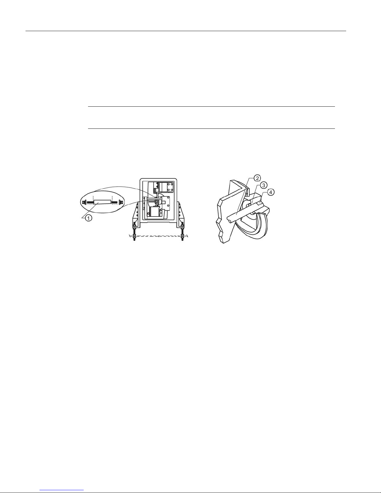
4.2
Sensing plate
1. Open the flowmeter housing access door.
2. With the sensing head cover removed, remove the taper pin.
3. Insert the sensing plate shaft fully into the sensing h ead socket.
Note
Ensure that the sensing plate shaft is installed wit h the flat side up.
4. Insert the taper pin (flat side down), from the left side.
5. Tighten the right taper pin nut to lock the sensing plate shaft in place.
6. Tighten the left taper pin nut.
①
Taper pin (flat side down)
③
Socket
②
Shaft
④
Flat side up
 Loading...