

Siemens SITRANS TW Operator's Manual
SITRANS T measuring instruments for temperature
© Siemens AG 2009
Transmitters for rail mounting
SITRANS TW
four-wire system, universal, HART
3
■
Overview
The user-friendly transmitters for the control room
The SITRANS TW universal transmitter is a further development
of the service-proven SITRANS T for the 4-wire system in a
mounting rail housing. With numerous new functions it sets new
standards for temperature transmitters.
With its diagnostics and simulation functions the SITRANS TW
provides the necessary insight during commissioning and operation. And using its HART interface the SITRANS TW can be
conveniently adapted with SIMATIC PDM to every measurement
task.
All SITRANS TW control room devices are available in a nonintrinsically safe version as well as in an intrinsically safe version
for use with the most stringent requirements.
■
Application
The SITRANS TW transmitter is a four-wire rail-mounted device
with a universal input circuit for connection to the following sensors and signal sources:
• Resistance thermometers
• Thermocouple elements
• Resistance-based sensors/potentiometers
• mV sensors
• As special version:
- V sources
- Current sources
The 4-wire rail-mounted SITRANS TW transmitter wire is designed for control room installation. It must not be mounted in
potentially explosive atmospheres.
All SITRANS TW control room devices are available in a nonintrinsically safe version as well as in an intrinsically safe version
for use with the most stringent requirements.
■
Function
Features
• Transmitter in four-wire system with HART interface
• Housing can be mounted on 35 mm rail or 32 mm G rail
• Screw plug connector
• All circuits electrically isolated
• Output signal: 0/4 to 20 mA or 0/2 to 10 V
• Power supplies: 115/230 V AC/DC or 24 V AC/DC
• Explosion protection [EEx ia] or [EEx ib] for measurements
with sensors in the hazardous area
• Temperature-linear characteristic for all temperature sensors
• Temperature-linear characteristic can be selected for all temperature sensors
• Automatic correction of zero and span
• Monitoring of sensor and cable for open-circuit and short-circuit
• Sensor fault and/or limit can be output via an optional sensor
fault/limit monitor
• Hardware write protection for HART communication
• Diagnostic functions
• Slave pointer functions
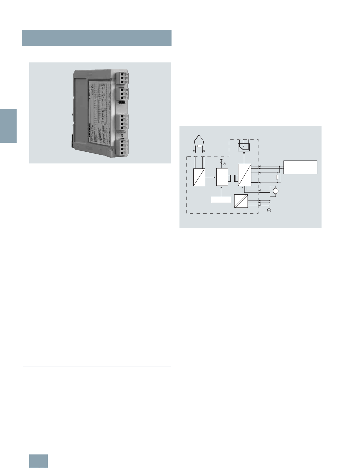
Mode of operation
TC
µC
5
9
Power
supply
7
10
D
Output
11
U or I
A
12
6
13
unit
Current test
A
0/4 ... 20 mA
U
H
HART modem/
communicator
RTD
8
A
1
4
D
2
EEPROM
3
The signal output by a resistance-based sensor (two-wire, threewire, four-wire system), voltage source, current source or thermocouple is converted by the analog-to-digital converter
(1, function diagram) into a digital signal. This is evaluated in the
microcontroller (2), corrected according to the sensor characteristic, and converted by the digital-to-analog converter (6) into an
output current (0/4 to 20 mA) or output voltage (0/2 to 10 V). The
sensor characteristics as well as the electronics data and the
data for the transmitter parameters are stored in the non-volatile
memory (3).
AC or DC voltages can be used as the power supply (13). Any
terminal connections are possible for the power supply as a result of the bridge rectifier in the power supply unit. The PE conductor is required for safety reasons.
A HART modem or a HART communicator permit parameterization of the transmitter using a protocol according to the HART
specification. The transmitter can be directly parameterized at
the point of measurement via the HART output terminals (10).
The operation indicator (4) identifies a fault-free or faulty operating state of the transmitter. The limit monitor (9) enables the signaling of sensor faults and/or limit violations. In the case of a current output, the current can be checked on a meter connected
to test socket (12).
Diagnosis and simulation functions
The SITRANS TW comes with extensive diagnosis and simulation functions.
Physical values can be defined with the simulation function. It is
thus possible to check the complete signal path from the sensor
input to Inside the control system without additional equipment.
The slave pointer functions are used to record the minimum and
maximum of the plant’s process variable.
3/38
Siemens FI 01 · 2010
SITRANS T measuring instruments for temperature
© Siemens AG 2009
■
Integration
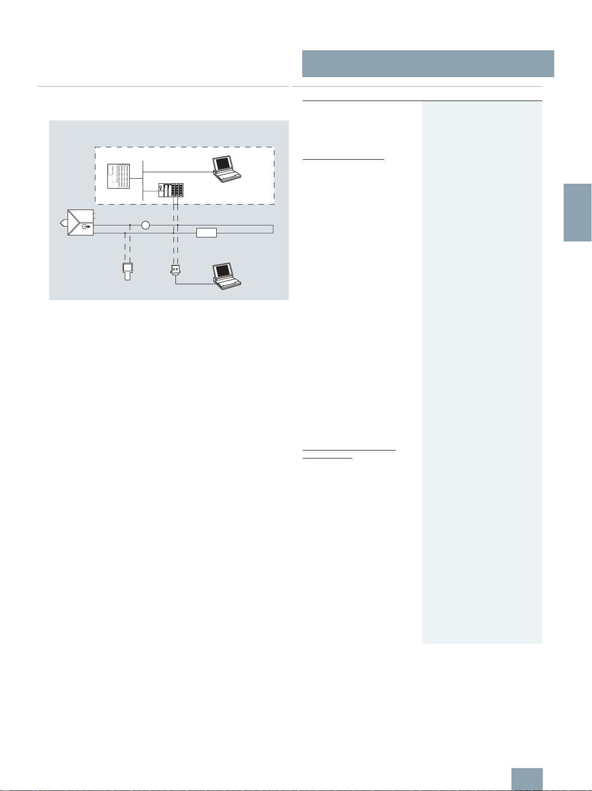
System configuration
SIMATIC S7-400
Control system
U
H
4...20 mA
SITRANS TW
transmitter
HART
communicator
Possible system configurations
A
or
HART
modem
ET 200M
or
Load
RS-232-C
The SITRANS TW transmitter as a four-wire rail-mounted device
can be used in a number of system configurations: as a standalone version or as part of a complex system environment, e.g.
with SIMATIC S7. All device functions are available via HART
communication.
Communication options through the HART interface:
• HART communicator
• HART modem connected to PC/laptop on which the appropriate software is available, e.g. SIMATIC PDM
• HART-compatible control system (e.g. SIMATIC S7-400 with
ET 200M)
SIMATIC PDM
PC/laptop with
SIMATIC PDM
Transmitters for rail mounting
four-wire system, universal, HART
■
Technical specifications
Input
Selectable filters to suppress the
line frequency
Resistance thermometer
Measured variable Temperature
Measured range
Measured span
Sensor type
• DIN IEC 751 Pt100 (DIN IEC 751)
• Acc. to JIS C 1604-81
• Acc. to DIN 43760
• Special type (R
Voltage measurement
Type of connection
Connection
Measuring range limits
Sensor breakage monitoring
Sensor short-circuit monitoring
Resistance-based sensors,
potentiometers
Measured variable Ohmic impedance
Measured range
Measured span
Voltage measurement
Type of connection
Connection
Input range
Sensor breakage monitoring
Sensor short-circuit monitoring
≤ 500 Ω) Multiples or parts of the defined
RTD
50 Hz, 60 Hz, also 10 Hz for special applications (line frequency
filter is similar with measuring frequency)
Parameterizable
Min. 25 °C (45 °F) x 1/scaling
factor
Pt100 (JIS C1604-81)
Ni100 (DIN 43760)
characteristic values can be
parameterized (e.g. Pt500, Ni120)
Temperature-linear, resistancelinear or customer-specific
• Normal connection
• Sum or parallel connection
• Mean-value or differential
connection
2, 3 or 4-wire circuit
Depending on type of connected
thermometer (defined range of
resistance thermometer)
Monitoring of all connections for
open-circuit (function can be
switched off)
Parameterizable response threshold (function can be switched off)
Parameterizable
Min. 10 Ω
Resistance-linear or customer-
specific
• Normal connection
• Differential connection
• Mean-value connection
2, 3 or 4-wire circuit
0 ... 6000 Ω;
with mean-value and difference circuits: 0 ... 3000 Ω;
Monitoring of all connections for
open-circuit (function can be
switched off)
Parameterizable response threshold (function can be switched off)
SITRANS TW
3
Siemens FI 01 · 2010
3/39

SITRANS T measuring instruments for temperature
© Siemens AG 2009
Transmitters for rail mounting
SITRANS TW
four-wire system, universal, HART
3
Thermocouple elements
Measured variable Temperature
Measured range
Measured span
Measuring range limits
Thermocouple
• Type B Pt30 %Rh/Pt6 %Rh (DIN IEC 584)
• Type C
• Type D
• Type E
• Type J
• Type K
• Type L
• Type N
• Type R
• Type S
• Type T
• Type U
Voltage measurement
Type of connection
Cold junction compensation
Sensor breakage monitoring
mV sensors
Measured variable DC voltage
Measured range
Measured span
Input range
Voltage measurement
Overload capacity of inputs
Input resistance
Sensor current
Sensor breakage monitoring
V sources
Measured variable DC voltage
Measured range
Voltage measurement
Input range/min. span
• Devices with 7NG3242-xxxx1 or
7NG3242-xxxx 0 with U/I plug
• Devices with 7NG3242-xxxx2
• Devices with 7NG3242-xxxx3
Sensor breakage monitoring
Parameterizable
Min. 50 °C (32.22 °F) x 1/scaling
factor
Depend. on type of thermocouple
element
W5 %-Re (ASTM 988)
W3 %-Re (ASTM 988)
NiCr/CuNi (DIN IEC 584)
Fe/CuNi (DIN IEC 584)
NiCr/Ni (DIN IEC 584)
Fe-CuNi (DIN 43710)
NiCrSi-NiSi (DIN IEC 584)
Pt13 %Rh/Pt (DIN IEC 584)
Pt10 %Rh/Pt (DIN IEC 584)
Cu/CuNi (DIN IEC 584)
Cu/CuNi (DIN 43710)
Special type
(-10 mV ≤ UTC ≤ 100 mV)
Temperature-linear, voltage-linear
or customer-specific
• Normal connection
• Sum connection
• Mean-value connection
• Differential connection
None, internal measurement, exter-
nal measurement or predefined
fixed value
Function can be switched off
Parameterizable
Min. 4 mV
-120 ... +1000 mV
Voltage-linear or customer-specific
Max. ± 3.5 V
≥ 1MΩ
Approx. 180 µA
Function can be switched off
Parameterizable
Voltage-linear or customer-specific
-1.2 V ... +10 V/0.04 V
-12 V ... +100 V/0.4 V
-120 V ... +140 V/4.0 V
Not possible
µA, mA sources
Measured variable DC voltage
Measured range
Voltage measurement
Input range/min. span
• Devices with 7NG3242-xxxx4 -12 µA ... +100 µA/0.4 µA
• Devices with 7NG3242-xxxx5
• Devices with 7NG3242-xxxx6
• Devices with 7NG3242-xxxx7 or
7NG3242-xxxx 0 with U/I plug
• Devices with 7NG3242-xxxx8
Sensor breakage monitoring
Output
Output signal Load-independent direct current
Current 0/4 ... 20 mA
• Overrange -0.5 ... +23.0 mA, continuously
• Output range following sensor fault
•Load
• Open-circuit voltage
Voltage 0/2 ... 10 V
• Overrange -0.25 ... +10.75 V, continuously
• Output range following sensor fault
• Load resistance
• Load capacitance
• Short-circuit voltage
• Electrical damping
- Adjustable time constant T
• Current source/voltage source
Sensor fault/limit signalling
Operation indicator
• Limit violation
• Overrange
Relay output
• Switching capacity
• Switching voltage
• Switching current
Overrange
Limit monitoring
• Operating delay 0 ... 10 s
• Monitoring functions of limit
module
• Hysteresis
By operation indicator, relay output
Parameterizable
Current-linear or customer-
specific
-120 µA ... +1000 µA/4 µA
-1.2 mA ... +10 mA/0.04 mA
-12 mA ... +100 mA/0.4 mA
-120 mA ... +1000 mA/4 mA
Not possible
0/4 ... 20 mA, can be switched to
load-independent DC voltage
0/2 ... 10 V using plug-in jumpers.
adjustable
-0.5 ... +23.0 mA, continuously
adjustable
≤ 650 Ω
≤ 30 V
adjustable
-0.25 ... +10.75 V, continuously
adjustable
≥ 1kΩ
≤ 10 nF
≤ 100 mA (not permanently short-
circuit-proof)
0 ... 100 s, in steps of 0.1 s
63
Continuously adjustable within the
total operating range
or HART interface
Flashing signal
Flashing frequency 5 Hz
Flashing frequency 1 Hz
Either as NO or NC contact with
1 changeover contact
≤ 150 W, ≤ 625 VA
≤ 125 V DC, ≤ 250 V AC
≤ DC 2.5 A
Signalling of sensor or line breakage and sensor short-circuit
• Sensor fault (breakage and/or
short-circuit)
• Lower and upper limit
• Window (combination of lower
and upper limits)
• Limit and sensor fault detection
can be combined
Parameterizable between 0 and
100 % of measuring range
3/40
Siemens FI 01 · 2010

SITRANS T measuring instruments for temperature
© Siemens AG 2009
Transmitters for rail mounting
SITRANS TW
four-wire system, universal, HART
Power supply
Universal power supply unit 115/230 V AC/DC or 24 V AC/DC
Tolerance range for power supply
• With 115/230 V AC/DC PSU 80 ... 300 V DC; 90 ... 250 V AC
• With 24 V AC/DC PSU
Tolerance range for mains frequency
Power consumption with
• 230 V AC ≤ 5 VA
• 230 V DC
• 24 V AC
• 24 V DC
Electrical isolation
Electrically isolated circuits Input, output, power supply and
Working voltage between all electrically isolated circuits
Measuring accuracy
Measurement error
• Error in the internal cold junction ≤ 3°C ± 0,1 °C/10 °C
• Error of external cold junction terminal 7NG3092-8AV
• Digital output
• Analog output I
Influencing effects (referred to the
digital output)
• Temperature drift
• Long-term drift
Influencing effects referred to the
analog output I
• Temperature drift
• Power supply
• Load with current output
• Load with voltage output
• Long-term drift (start-of-scale
value, span)
Response time (T
cal damping)
Electromagnetic compatibility
Certificate and approvals
ATEX To DIN EN 50014: 1997,
Intrinsic safety to EN 50 020
• for 7NG3242-xAxxx II (1) G D [EEx ia/ib ] IIB
• for 7NG3242-xBxxx
EC-Type Examination Certificate
or U
AN
or U
AN
AN
without electri-
63
AN
18 ... 80 V DC; 20.4 ... 55.2 V AC
(in each case interruption-resistant
up to 20 ms in the complete tolerance range)
47 ... 63 Hz
≤ 5 W
≤ 5 VA
≤ 5 W
sensor fault/limit monitoring output
are electrically isolated from one
another. The HART interface is
electrically connected to the output.
The voltage U
terminals must not exceed 300 V
(≤ 5.4 °F ± 0,18 °F/18 °F)
≤ 0.5 °C ± 0,1 °C/10 °C
(≤ 0.9 °F ± 0.18 °F/18 °F)
See "Digital error"
≤ 0.05 % of span in addition to
digital error
Compared to the max. span:
≤ 0.08 %/10 °C (≤ 0.08 %/18 °F)
≤ 0.2 % in the range -10 ... +60 °C
(14 ... 140 °F)
≤ 0.1 %/year
Compared to the span:
≤ 0.08 %/10°C (≤ 0.08 %/18 °F)
≤ 0.2 % in the range -10 ... +60 °C
(14 ... 140 °F)
≤ 0.05 %/10 V
≤ 0.05 % with change from
50 ... 650 Ω
≤ 0.1 % with change in load current
from 0 ... 10 mA
≤ 0.03 %/month
≤ 0.2 s
According to EN 61326 and
NAMUR NE21
EN 50020: 1994
II (1) G D [EEx ia/ib ] IIC
TÜV (German Technical Inspec-
torate) 01 ATEX 1675
between any two
eff
Rated conditions
Installation conditions
Location (for devices with explo-
sion protection)
• Transmitters Outside the potentially explosive
•Sensor
Ambient conditions
Permissible ambient temperature -25 ... +70 °C (-13 ... +158 °F)
Permissible storage temperature
Climatic class
• Relative humidity 5 ... 95 %, no condensation
Design
Weight Approx. 0.24 kg (0.53 lb)
Enclosure material
Degree of protection to IEC 529
Degree of protection to VDE 0100
Type of installation
Electrical connection/process connection
Parameterization interface
Protocol HART, version 5.9
Load with connection of
• HART communicator 230 ... 650 Ω
•HART modem
Software for PC/laptop
atmosphere
Within the potentially explosive
atmosphere zone 1 (also in zone 0
in conjunction with the prescribed
protection requirements for the
sensor)
-40 ... +85 °C (-40 ... +185 °F)
PBT, glass-fibre reinforced
IP20
Protection class I
35-mm top hat rail (1.38 inch)
(DIN EN 50022) or 32-mm G-type
rail (1.26 inch) (DIN EN 50035)
Screw plug connectors,
max. 2.5 mm² (0.01 inch²)
230 ... 500 Ω
SIMATIC PDM version V5.1 and
later
3
Siemens FI 01 · 2010
3/41
 Loading...