

Siemens SITRANS TSinsert, SITRANS TS100, SITRANS TS200, SITRANS TS300, SITRANS TS500 Compact Operating Instructions

English ······························································································· 3
Български ························································································ 43
Čeština ····························································································· 84
Suomi······························································································ 124
Slovenčina······················································································· 165
Slovenščina ····················································································· 205
1

SITRANS
Temperature sensors
SITRANS TSinsert/TS100/TS200/TS300/TS500
Compact Operating Instructions
Legal information
Warning notice system
DANGER
will
WARNING
may
CAUTION
NOTICE
Qualified Personnel
personnel qualified
Proper use of Siemens products
WARNING
1
Introduction
See also
This manual contains notices you have to observe in order to ensure your personal safety, as well as to prevent damage to property. The
notices referring to your personal safety are highlighted in the manual by a safety alert symbol, notices referring only to property damage
have no safety alert symbol. These notices shown below are graded according to the degree of danger.
indicates that death or severe personal injury
indicates that death or severe personal injury
indicates that minor personal injury can result if proper precautions are not taken.
indicates that property damage can result if proper precautions are not taken.
If more than one degree of danger is present, the warning notice representing the highest degree of danger will be used. A notice warning of
injury to persons with a safety alert symbol may also include a warning relating to property damage.
The product/system described in this documentation may be operated only by
the relevant documentation, in particular its warning notices and safety instructions. Qualified personnel are those who, based on their
training and experience, are capable of identifying risks and avoiding potential hazards when working with these products/systems.
Note the following:
Siemens products may only be used for the applications described in the catalog and in the relevant technical documentation. If products
and components from other manufacturers are used, these must be recommended or approved by Siemens. Proper transport, storage,
installation, assembly, commissioning, operation and maintenance are required to ensure that the products operate safely and without any
problems. The permissible ambient conditions must be complied with. The information in the relevant documentation must be observed.
result if proper precautions are not taken.
result if proper precautions are not taken.
for the specific task in accordance with
These instructions contain all information required to commission and use the device. It is your responsibility to read the
instructions carefully prior to installation and commissioning. In order to use the device correctly, first review its principle of
operation.
The instructions are aimed at persons mechanically installing the device, connecting it electronically, configuring the
parameters and commissioning it, as well as service and maintenance engineers.
Technical support (Page 42)
© Siemens AG 2013. All rights reserved
A5E32897051-01, 09/2013
3
1.1
History of operating instructions
Edition
Remark
1.2
Checking the consignment
WARNING
Using a damaged or incomplete device
1.3
Transportation and storage
CAUTION
Insufficient protection during storage
1.4
Notes on warranty
See also
The following table contains important changes to the previous version of the documentation:
01 Edition was never published
02
10/2012
03
03/2013
04
07/2013
1. Check the packaging and the device for visible damage caused by inappropriate handling during shipping.
2. Report any claims for damages immediately to the shipping company.
3. Retain damaged parts for clarification.
4. Check the scope of delivery by comparing your order to the shipping documents for correctness and completeness.
First edition of instructions
Added warning notes and updated electrical data
Added warning notes and updated electrical data, added SITRANS TS300
Danger of explosion in hazardous areas.
● Do not use damaged or incomplete devices.
To guarantee sufficient protection during transport and storage, observe the following:
● Keep the original packaging for subsequent transportation.
● Devices/replacement parts should be returned in their original packaging.
● If the original packaging is no longer available, ensure that all shipments are properly packaged to provide sufficient
protection during transport. Siemens cannot assume liability for any costs associated with transportation damages.
The packaging only provides limited protection against moisture and infiltration.
● Provide additional packaging as necessary.
Special conditions for storage and transportation of the device are listed in "Technical data".
The contents of this manual shall not become part of or modify any prior or existing agreement, commitment or legal
relationship. The sales contract contains all obligations on the part of Siemens as well as the complete and solely applicable
warranty conditions. Any statements regarding device versions described in the manual do not create new warranties or
modify the existing warranty.
The content reflects the technical status at the time of publishing. Siemens reserves the right to make technical changes in
the course of further development.
Contacts (http://www.siemens.com/processinstrumentation/contacts)
SITRANS T product information (http://www.siemens.com/sitranst)
Instructions and manuals (http://www.siemens.com/processinstrumentation/documentation)
SITRANS TSinsert/TS100/TS200/TS300/TS500
4 A5E32897051-01, 09/2013
2
Safety information
2.1
Requirements for safe use
Symbol
Description
2.1.1
Laws and directives
2.1.2
Conformity with European directives
See also
WARNING
Improper device modifications
2.2
Requirements for special applications
This device left the factory in good working condition. In order to maintain this status and to ensure safe operation of the
device, observe these instructions and all the specifications relevant to safety.
Observe the information and symbols on the device. Do not remove any information or symbols from the device. Always
keep the information and symbols in a completely legible state.
Pay attention to the operating instructions
Observe the test certification, provisions and laws applicable in your country during connection, assembly and operation.
These include, for example:
● National Electrical Code (NEC - NFPA 70) (USA)
● Canadian Electrical Code (CEC) (Canada)
Further provisions for hazardous area applications are for example:
● IEC 60079-14 (international)
● EN 60079-14 (EC)
The CE marking on the device symbolizes the conformity with the following European directives:
Electromagnetic compatibility EMC
2004/108/EC
Atmosphère explosible ATEX
94/9/EC
The applicable directives can be found in the EC conformity declaration of the specific device.
Certificates (http://www.siemens.com/processinstrumentation/certificates)
Directive of the European Parliament and of the Council on the approximation of the
laws of the Member States relating to electromagnetic compatibility and repealing
Directive 89/336/EEC.
Directive of the European Parliament and the Council on the approximation of the
laws of the Member States concerning equipment and protective systems intended
for use in potentially explosive atmospheres.
Danger to personnel, system and environment can result from modifications to the device, particularly in hazardous areas.
● Only carry out modifications that are described in the instructions for the device. Failure to observe this requirement
cancels the manufacturer's warranty and the product approvals.
Due to the large number of possible applications, each detail of the described device versions for each possible scenario
during commissioning, operation, maintenance or operation in systems cannot be considered in the instructions. If you need
additional information not covered by these instructions, contact your local Siemens office or company representative.
SITRANS TSinsert/TS100/TS200/TS300/TS500
A5E32897051-01, 09/2013
5
Note
Operation under special ambient conditions
2.3
Use in hazardous areas
2.3.1
Qualified personnel for hazardous area applications
Qualified personnel for hazardous area applications
WARNING
Unsuitable device for the hazardous area
See also
WARNING
Loss of safety of device with type of protection "Intrinsic safety Ex i"
We highly recommend that you contact your Siemens representative or our application department before you operate the
device under special ambient conditions as can be encountered in nuclear power plants or when the device is used for
research and development purposes.
Persons who install, connect, commission, operate, and service the device in a hazardous area must have the following
specific qualifications:
● They are authorized, trained or instructed in operating and maintaining devices and systems according to the safety
● They are authorized, trained, or instructed in carrying out work on electrical circuits for hazardous systems.
● They are trained or instructed in maintenance and use of appropriate safety equipment according to the pertinent safety
Technical data (Page 22)
regulations for electrical circuits, high pressures, aggressive, and hazardous media.
regulations.
Danger of explosion.
● Only use equipment that is approved for use in the intended hazardous area and labelled accordingly.
If the device has already been operated in non-intrinsically safe circuits or the electrical specifications have not been
observed, the safety of the device is no longer ensured for use in hazardous areas. There is a danger of explosion.
● Connect the device with type of protection "Intrinsic safety" solely to an intrinsically safe circuit.
● Observe the specifications for the electrical data on the certificate and in Chapter "Technical data (Page 22)".
SITRANS TSinsert/TS100/TS200/TS300/TS500
6 A5E32897051-01, 09/2013
3
Description
3.1
Overview
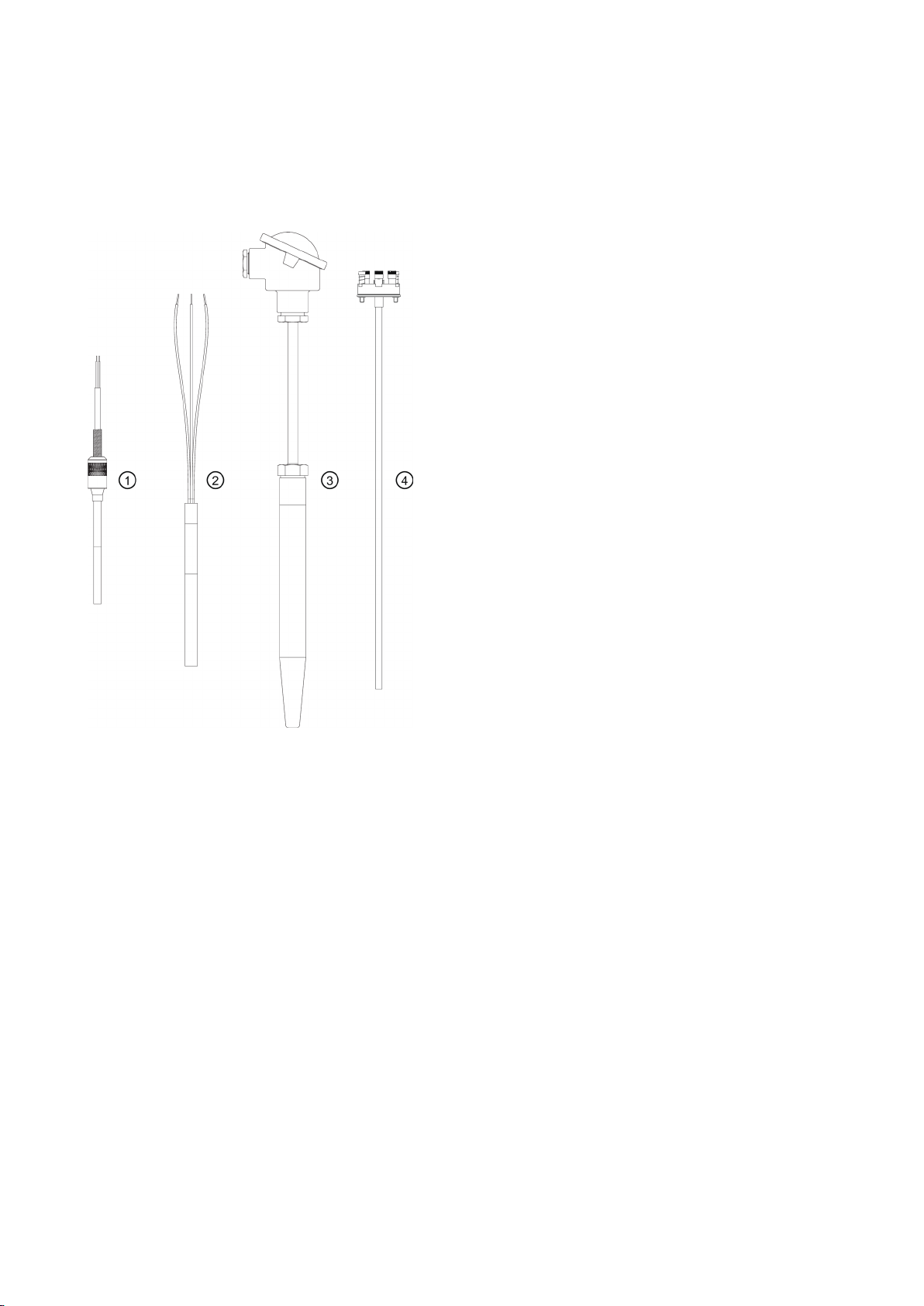
SITRANS TS product family
①
general use, compact design with connecting cable
②
general use, compact design
③
general use, modular design with connection head
④
SITRANS TSinsert measuring insert for use in the SITRANS TS500 series
Elementary sensors
3.2
Application
SITRANS TS100 7MC71..
SITRANS TS200 7MC72..
SITRANS TS500 7MC75..
Resistance thermometers or thermocouples can be used for temperature measurement.
The temperature sensors of the SITRANS TS product family are used for measuring temperatures in industrial plants.
Depending on the specifications, sensors can be combined with different connection heads, extension tubes, and process
connections. This makes the sensors suitable for a variety of process engineering applications, e.g. in the following sectors:
● Petrochemical industry
● Pharmaceuticals industry
● Biotechnology
● Foodstuffs
SITRANS TSinsert/TS100/TS200/TS300/TS500
A5E32897051-01, 09/2013
7
3.3
Functional principles
3.4
Nameplate structure
Positioning of nameplate
Note
SITRANS TS100/TS200 nameplate
Device
Positioning of the nameplate
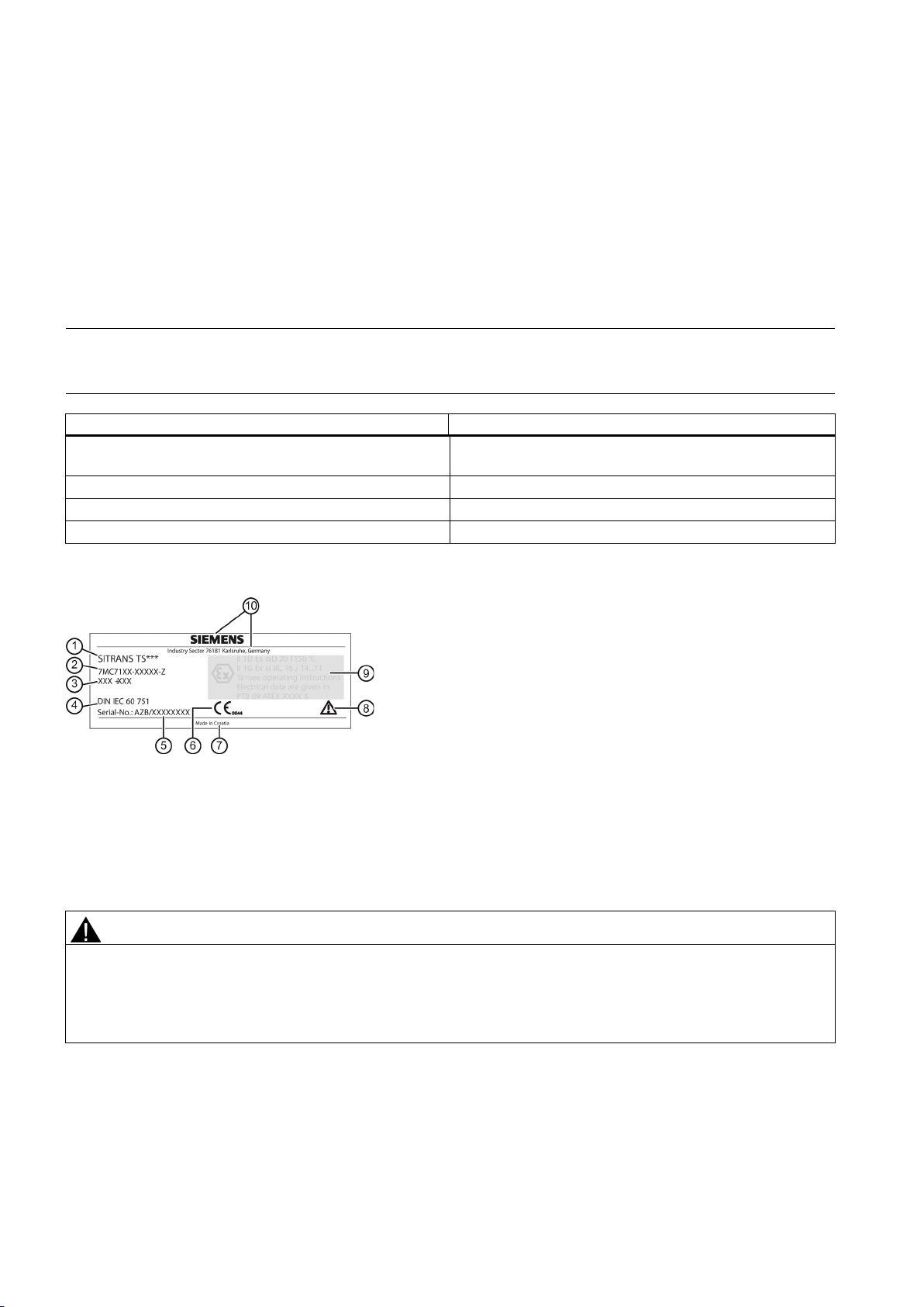
Example of nameplate
①
②
③
④
⑤
⑥
⑦
⑧
⑨
⑩
WARNING
Loss of safety of device with type of protection "Intrinsic safety Ex i"
● Observe the specifications for the electrical data on the certificate and in Chapter "Technical data".
Two different measuring principles are used for measuring temperatures.
● With resistance thermometers, the temperature is measured as a change in resistance. Resistance thermometers
contain Pt100 sensor elements in accordance with IEC 60751.
● With thermocouples, the temperature is the change in voltage (Seebeck effect). The thermocouples are in accordance
with IEC 584/DIN EN 60584.
Before commissioning, make sure the nameplate is securely fastened to the temperature sensor in a visible location
SITRANS TSinsert 7MC701. On the bottom of the connecting plate or at the outer
periphery of the ANSI adapter.
SITRANS TS100 7MC71.. On the sensor cable
SITRANS TS200 7MC72.. On the connector or on the sensor
SITRANS TS500 7MC75.. On the connection head
Product name
Additional information on the type
Serial number
Place of manufacture
Type-specific information Explosion
protection/electrical data
If the device has already been operated in non-intrinsically safe circuits or the electrical specifications have not been
observed, the safety of the device is no longer ensured for use in hazardous areas. There is a danger of explosion.
● Connect the device with type of protection "Intrinsic safety" solely to an intrinsically safe circuit.
Order number (machine-readable product code)
Valid standard for the device
CE marking
Consult the operating instructions.
Manufacturer´s specifications
SITRANS TSinsert/TS100/TS200/TS300/TS500
8 A5E32897051-01, 09/2013

3.5
Incorrect selection of type of protection
WARNING
Incorrect selection of type of protection
3.6
Temperature transmitter for SITRANS TS500
Transmitter
Features
Sensor
● Po: 12.5 mW
Note
SITRANS TS500 IEC Ex
3.7
Measuring inserts for SITRANS TS500
Danger of explosion in areas subject to explosion hazard.
This device is approved for several types of protection.
1. Decide in favor of one type of protection.
2. Connect the device in accordance with the selected type of protection.
3. In order to avoid incorrect use at a later point, make the types of protection that are not used permanently
unrecognizable on the nameplate.
The following head-mounted transmitters can be combined with the temperature sensors SITRANS TS500:
TH100
● Base device
● Output 4 ... 20 mA
● Can be configured using simple software
TH200
● Universal device
● Output 4 ... 20 mA
● Can be configured using simple software
● P
TH300
● Universal
● Output 4 ... 20 mA / HART
● Diagnostic functions
● P
TH400
● Output: PROFIBUS PA or FOUNDATION Fieldbus.
● Sensor redundancy
● Diagnostics
● P
1)
Resistance thermometers
2)
Thermocouple
: 37 mW
o
: 37 mW
o
: 12.5 mW
o
only
1)
or 2)
1)
or 2)
1)
or 2)
1)
If the contained SITRANS TH transmitter is not IEC Ex compliant, the TS500 nameplate has ATEX marking only.
Measuring inserts for SITRANS TS500 temperature sensors are available in three variants:
● Variant 1:
DIN mounting disk for accommodating a transmitter or ceramic socket.
● Variant 2:
Fixed connection of the ends of the mineral insulated cable with a DIN ceramic socket.
● Variant 3:
Measuring insert in a spring-loaded adapter (ANSI)
SITRANS TSinsert/TS100/TS200/TS300/TS500
A5E32897051-01, 09/2013
9
3.8
Connection heads for SITRANS TS500
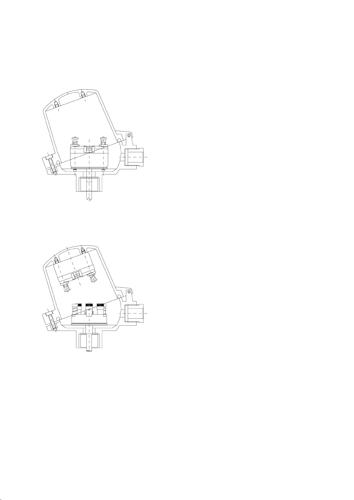
The transmitters can be mounted in connection heads of type B and bigger. The following mounting types are possible:
● Measuring insert mounting
– Standard type with compact design
– Measuring insert (sensor) and transmitter form one unit
Figure 3-1 Measuring insert mounting of transmitter
● Hinged cover mounting
– Standard type for connection heads of type BC0: B head with high hinged cover
– Separate maintenance of the measuring insert and the transmitter is possible.
Figure 3-2 Hinged cover mounting of transmitter
SITRANS TSinsert/TS100/TS200/TS300/TS500
10 A5E32897051-01, 09/2013
4
Install
4.1
Basic safety instructions
CAUTION
Hot surfaces resulting from hot process media
WARNING
Unsuitable connecting parts
See also
WARNING
Exceeded maximum ambient or process media temperature
WARNING
Open cable inlet or incorrect cable gland
WARNING
Incorrect mounting at Zone 0
CAUTION
External stresses and loads
Danger of burns resulting from surface temperatures above 70 °C (155 °F).
● Take appropriate protective measures, for example contact protection.
● Make sure that protective measures do not cause the maximum permissible ambient temperature to be exceeded.
Refer to the information in Chapter "Technical data (Page 22)".
Danger of injury or poisoning.
In case of improper mounting hot, toxic and corrosive process media could be released at the connections.
● Ensure that connecting parts (such as flange gaskets and bolts) are suitable for connection and process media.
Technical data (Page 22)
Danger of explosion in hazardous areas.
Device damage.
● Make sure that the maximum permissible ambient and process media temperatures of the device are not exceeded.
Refer to the information in Chapter "Technical data (Page 22)".
Danger of explosion in hazardous areas.
● Close the cable inlets for the electrical connections. Only use cable glands or plugs which are approved for the relevant
type of protection.
Danger of explosion in hazardous areas.
● Ensure sufficient tightness at the process connection.
● Observe the standard IEC/EN 60079-14.
Damage to device by severe external stresses and loads (e.g. thermal expansion or pipe tension). Process media can be
released.
● Prevent severe external stresses and loads from acting on the device.
SITRANS TSinsert/TS100/TS200/TS300/TS500
A5E32897051-01, 09/2013
11
CAUTION
High vibration area
4.1.1
Installation and location requirements
CAUTION
Direct sunlight
4.1.2
Proper mounting
NOTICE
Incorrect mounting
Note
Loss of degree of protection
Damage to device if the enclosure is open or not properly closed. The degree of protection specified on the nameplate is no
CAUTION
Loss of IP protection
4.2
Install
Process connection
DANGER
Protective tube ruptures
Especially with the stainless steel housing version, use short extension lengths or external supports when used in a high
vibration area.
Device damage.
The device can overheat or materials become brittle due to UV exposure.
● Protect the device from direct sunlight.
● Make sure that the maximum permissible ambient temperature is not exceeded. Refer to the information in Chapter
"Technical data (Page 22)".
The device can be damaged, destroyed, or its functionality impaired through improper mounting.
● Before installing ensure there is no visible damage to the device.
● Make sure that process connectors are clean, and suitable gaskets and glands are used.
● Mount the device using suitable tools. Refer to the information in Chapter "Technical data (Page 22)", for example
installation torques requirements.
longer guaranteed.
Do not unscrew the device housing from the mounted parts with NPT threaded connection
Protective tubes that are not suitable for the process or application in question can rupture and result in serious damage to
property and personal injuries
Make sure that the protective tube is suitable for the respective mounting method and application. If necessary, check the
selection and order data of your protective tube.
The devices are delivered with different connection heads and different process connections depending on the
specifications. The following guidelines apply:
SITRANS TSinsert/TS100/TS200/TS300/TS500
12 A5E32897051-01, 09/2013

Note
SITRANS TS500 barstock version
Device extension and protective tube torque requirements
CAUTION
Gasket between extension and protective tube
Device extension and protective tube
torque requirements
Device device head and extension torque requirements
Connection type
Torque value
Head type
Torque value
Rule of thumb for installation
Estimation of immersion depth
Medium
Immersion depth (calculation)1)
● Assemble the process prior to the electrical installation.
● Make sure prior to mounting that the device is appropriate with regard to the process connection, media compatibility,
temperature resistance and measuring range.
● The gaskets used must be suitable for the process connection and resistant to the measured media.
For SITRANS TS500 barstock version without flange (type 4), the customer has to complete the mounting of the device
extension to the protective tube, see
table below
Gasket between device extension and protective tube can only be used once
● Use required torque values between device extension and protective tube, see
table below.
● Use required torque values between the device head and extension if customer adjustments are necessary (M24
connections only), see
table below.
Table 4-1 Device extension and protective tube torque requirements
M14 thread 25 Nm
M18 thread 40 Nm
G½ thread 50 Nm
Table 4-2 Device device head and extension torque requirements
Metal head 28 Nm
Plastic head (BP0) 15 Nm
Plastic head (BM0) 5 Nm
Prevent faults caused by heat dissipation by observing the following rules:
● Select the largest possible immersion depth. Estimate the immersion depth using the formulas specified below.
● Select a measuring location with a high flow rate.
● Ensure that there is sufficient thermal insulation of the external components of the thermometer.
● Ensure that external parts have as small surfaces as possible.
● Select the optimum mounting position for the process in question.
Water Immersion depth ≥ TSL + (5 x ∅
Air Immersion depth ≥ TSL + (10 bis 15 x ∅
1)
TSL = Temperature Sensitive Length
SITRANS TSinsert/TS100/TS200/TS300/TS500
A5E32897051-01, 09/2013
protective tube
protective tube
)
)
13
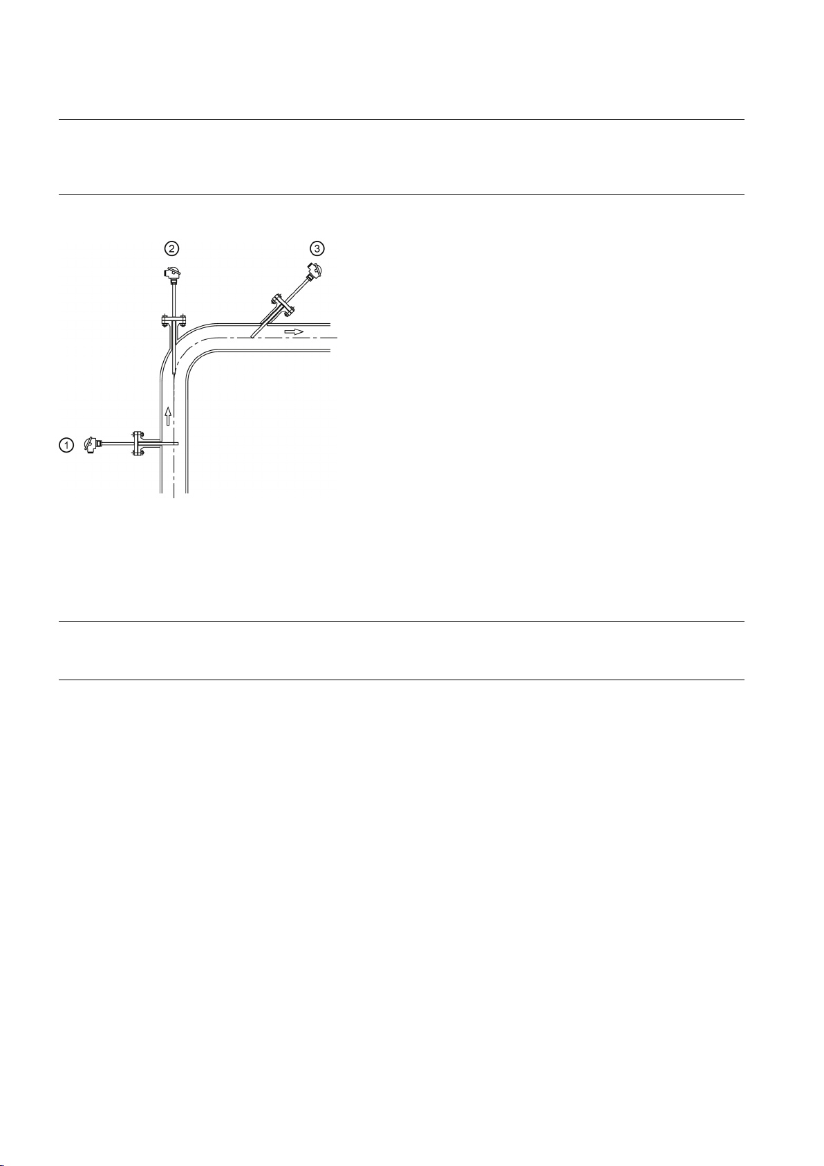
Mounting positions
Note
Mounting positions for small pipe diameters
in the diagram "Mounting
①
At a right angle to the flow
②
In a bend upstream
③
In a narrow cable at an angle upstream
4.3
Install SITRANS TS300 Clamp-on
Note
Measurement position
With small pipe diameters, mount the sensors upstream at an angle or in an elbow, see ② and ③
positions".
The following diagram shows the possible mounting positions of the sensors:
Figure 4-1 Mounting positions
Install on circular pipes only, avoid installation next to angled pipes, near slide valves, valves, pumps, etc.
1. Define the measurement position.
2. Apply heat sink compound to the metallic part of the temperature sensor.
3. For standard version: halved pipe collar allows for quick and easy mounting on the pipe using two mounting screws.
For bracket version: mount on pipe using one mounting screw.
– If the pipe is not fully occupied by medium during installation, mount the temperature sensor on the underside of the
pipe.
4. Firmly tighten the mounting screws (4 Nm torque).
5. Mount the vibration protection and hand-tighten.
– You can remove the measuring insert only after you have released the Pt100 recessed grip screw(s).
– Do not twist the housing.
– Use Pt100 recessed grip screw for installation, only.
– Do not apply force to the transmitter housing (e. g. during opening/closing of lid).
– Because the locking plugs are fitted with internal gaskets they are only suited for ambient temperatures to 100 °C
(212 °F).
SITRANS TSinsert/TS100/TS200/TS300/TS500
14 A5E32897051-01, 09/2013
4.4
Uninstall
WARNING
Incorrect disassembly
5
Connect
5.1
Basic safety instructions
WARNING
Unsuitable cables and/or cable glands
See also
WARNING
Improper power supply
WARNING
Unsafe extra-low voltage
The following dangers may result through incorrect disassembly:
- Injury through electric shock
- Danger through emerging media when connected to the process
- Danger of explosion in hazardous area
In order to disassemble correctly, observe the following:
● Before starting work, make sure that you have switched off all physical variables such as pressure, temperature,
electricity etc. or that they have a harmless value.
● If the device contains dangerous media, it must be emptied prior to disassembly. Make sure that no environmentally
hazardous media are released.
● Secure the remaining connections so that no damage can result if the process is started unintentionally.
Danger of explosion in hazardous areas.
● Only use suitable cables and cable glands complying with the requirements specified in Chapter "Technical data
(Page 22)".
● Tighten the cable glands in accordance with the torques specified in Chapter "Technical data (Page 22)".
● When replacing cable glands use only cable glands of the same type.
● After installation check that the cables are seated firmly.
Construction (Page 25)
Danger of explosion in hazardous areas as result of incorrect power supply, e.g. using direct current instead of alternating
current.
● Connect the device in accordance with the specified power supply and signal circuits. The relevant specifications can
be found in the certificates, in Chapter "Electrical data (Page 26)" or on the nameplate.
Danger of explosion in hazardous areas due to voltage flashover.
● Connect the device to an extra-low voltage with safe isolation (SELV).
SITRANS TSinsert/TS100/TS200/TS300/TS500
A5E32897051-01, 09/2013
15
WARNING
Lack of equipotential bonding
Exception
WARNING
Unprotected cable ends
WARNING
Loss of degree of protection
WARNING
Lemo plug in hazardous areas
WARNING
Improper laying of shielded cables
WARNING
Connecting device in energized state
Exceptions
Note
Electromagnetic compatibility (EMC)
Danger of explosion through compensating currents or ignition currents through lack of equipotential bonding.
● Ensure that the device is potentially equalized.
: It may be permissible to omit connection of the equipotential bonding for devices with type of protection
"Intrinsic safety Ex i".
Danger of explosion through unprotected cable ends in hazardous areas.
● Protect unused cable ends in accordance with IEC/EN 60079-14.
When connecting the SITRANS TS100 or TS200 with type protection "Intrinsically safe", ensure the following:
● Adhere to the requirements for electrical connection seperation
● Use IP54 rated enclosure
For Lemo plug version (7MC7xxx-xxxx2-xxx) make sure the cable ends are in an environment free from dust, water, or
shock
Danger of explosion through compensating currents between hazardous area and the non-hazardous area.
● Only ground shielded cables that run into the hazardous area at one end.
● If grounding is required at both ends, use an equipotential bonding conductor.
Danger of explosion in hazardous areas.
● Connect devices in hazardous areas only in a de-energized state.
:
● Circuits of limited energy may also be connected in the energized state in hazardous areas.
● Exceptions for type of protection "Non-sparking nA" (Zone 2) are regulated in the relevant certificate
You can use this device in industrial environments, households and small businesses.
For metal housings there is an increased electromagnetic compatibility compared to high-frequency radiation. This
protection can be increased by grounding the housing, see Chapter "Electrical connection (Page 17)".
SITRANS TSinsert/TS100/TS200/TS300/TS500
16 A5E32897051-01, 09/2013
Note
Improvement of interference immunity
5.1.1
For SITRANS TSinsert/TS200/TS500
NOTICE
Ambient temperature too high
5.1.2
For SITRANS TS500
NOTICE
Condensation in the device
5.1.3
For SITRANS TS100/TS200
WARNING
Use of plug connectors in explosive dust atmosphere
5.2
Electrical connection
Procedure
Note
Connection sequence
● Lay signal cables separate from cables with voltages > 60 V.
● Use cables with twisted wires.
● Keep device and cables in distance to strong electromagnetic fields.
● Use shielded cables to guarantee the full specification according to HART.
● Refer to HART communication information in Chapter "Technical data (Page 22)".
Damage to cable sheath.
● At an ambient temperature ≥ 60 °C (140 °F), use heat-resistant cables suitable for an ambient temperature at least 20
Damage to device through formation of condensation if the temperature difference between transportation or storage and
the mounting location exceeds 20 °C (68°F).
● Before taking the device into operation let the device adapt for several hours in the new environment.
Danger of explosion.
Temperature sensors of the SITRANS TS100 and SITRANS TS200 series must not be used together with plug connectors
in atmospheres with combustible dust.
● Do not use plug connectors in areas with combustible dust.
°C (68 °F) higher.
Install the temperature transmitter before connecting the temperature sensor electrically.
1. Release the fixing screws on the enclosure cover and remove the enclosure cover.
2. Insert the connecting cable through the cable gland.
3. Connect the wires to the relevant connecting terminals. Observe the terminal assignment.
– Electrical connection of resistance thermometers (Page 18)
– Electrical connection of thermocouples (Page 18)
– Electrical connection of connectors (Page 19)
SITRANS TSinsert/TS100/TS200/TS300/TS500
A5E32897051-01, 09/2013
17
See also
5.3
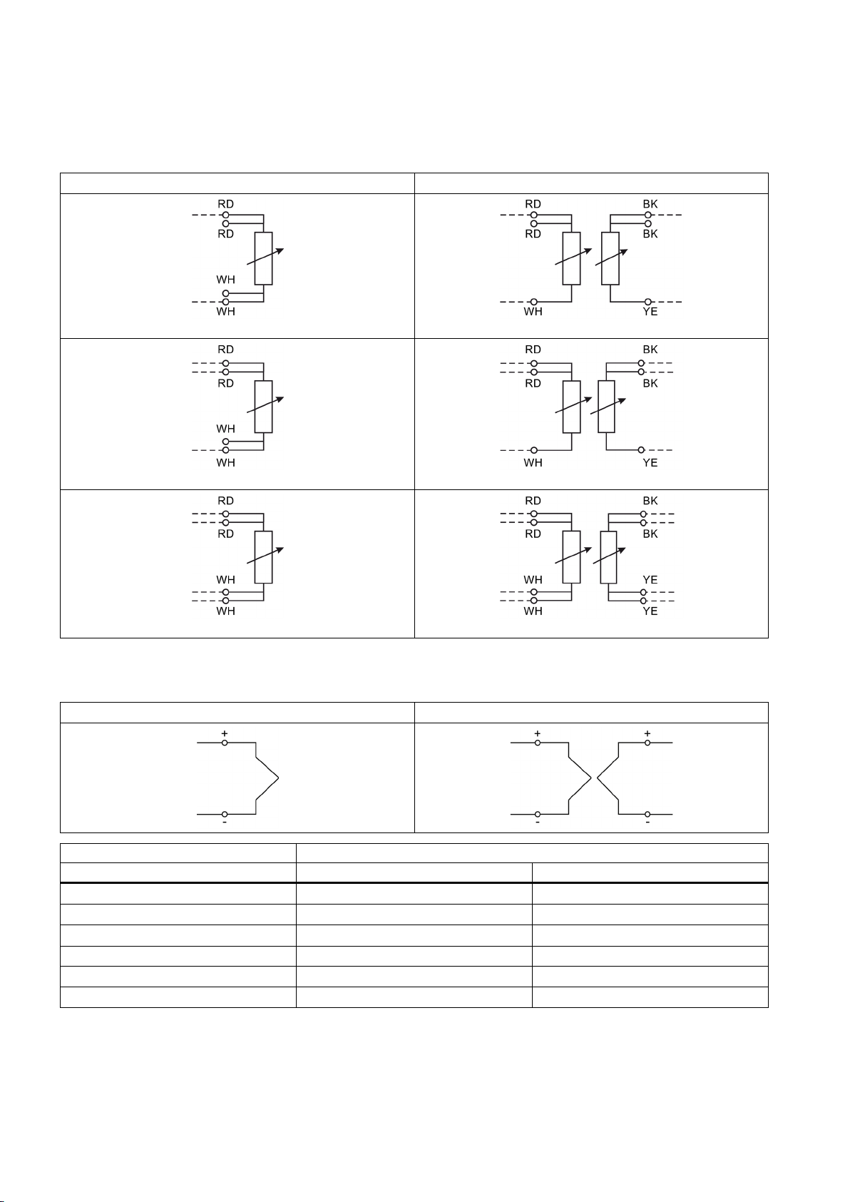
Electrical connection of resistance thermometers
5.4
Electrical connection of thermocouples
Thermocouples
Cable colors
Type + -
J
K
N
E
L
T
Electrical data (Page 26)
1 x Pt100 2 x Pt100
2-wire connection
3-wire connection
4-wire connection
Abbreviation of color: RD = red; WH = white; YE = yellow; BK = black
1 thermocouple 2 thermocouples
2-wire connection
3-wire connection
4-wire connection
Black White
Green White
Pink White
Brown White
Red Blue
Red White
SITRANS TSinsert/TS100/TS200/TS300/TS500
18 A5E32897051-01, 09/2013
5.5
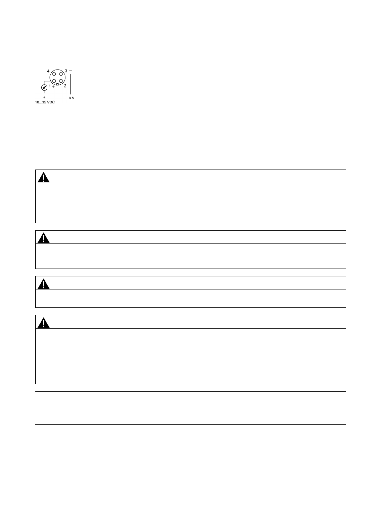
Electrical connection of connectors
6
Commission
6.1
Basic safety instructions
WARNING
Improper commissioning in hazardous areas
WARNING
Hot surfaces
WARNING
Loss of explosion protection
WARNING
Opening device in energized state
Exception
Note
Loss of degree of protection
Damage to device if the enclosure is open or not properly closed. The degree of protection specified on the nameplate is no
M12 x 1 connection with SITRANS TH100 transmitter
Figure 5-1 2-wire connection, 4 ... 20 mA
Device failure or danger of explosion in hazardous areas.
● Do not commission the device until it has been mounted completely and connected in accordance with the information
in Chapter "Technical data (Page 22)".
● Before commissioning take the effect on other devices in the system into account.
Danger of burns resulting from hot surfaces.
● Take corresponding protective measures, for example by wearing protective gloves.
Danger of explosion in hazardous areas if the device is open or not properly closed.
Danger of explosion in areas subject to explosion hazard.
● Only open the device in a de-energized state.
● Check prior to commissioning that the cover, cover locks, and cable inlets are assembled in accordance with the
directives.
: Devices having the type of protection "Intrinsic safety Ex i" may also be opened in energized state in hazardous
areas.
longer guaranteed.
SITRANS TSinsert/TS100/TS200/TS300/TS500
A5E32897051-01, 09/2013
19

6.2
Commissioning
Requirements
Procedure
7
Service and maintenance
7.1
Service and maintenance
Recalibration
Note
Recalibration intervals
Recalibration of SITRANS TS300
Description
Recalibration procedure
Verify that the following commissioning conditions are satisfied:
● You have connected the sensors correctly. For further details, see:
– Electrical connection of resistance thermometers (Page 18)
– Electrical connection of thermocouples (Page 18)
● Verify that the electrical connections are firmly tightened to the suitable torque.
● The following applies in particular with device versions with explosion protection:
– Verify whether the cable glands are appropriate for the process and are correctly tightened.
– The electrical data must match the specified ex-relevant values.
● All seals must be present, placed correctly and undamaged.
1. Close the connection head. Fully screw on the cover for device versions with flameproof enclosures.
2. Connect the sensor integrated in the process to the power supply.
Temperature sensors are essentially maintenance-free. However, we recommend recalibration under the following
conditions:
● Processes with strong vibrations or changes in temperature.
● Food, pharma, biotechnology applications (annually), TS300 only.
● Processes that demand high measuring accuracy and safety.
Define the recalibration intervals for the specific process or plant. With constant operating temperatures and a low load,
the reference values are as follows:
● < 2 years at temperatures up to 400 °C
● < 5 years at temperatures up to 200 °C
Clamp-on version Do not disconnect the pipe sleeve from the pipe - leave the
measuring position unchanged for reproducible measurement.
It is not necessary to disconnect the power supply to perform
calibration.
Loosen recessed grip screw(s) to remove the Pt100 connector or
housing and unscrew the measuring insert from the pipe collar.
Block calibrators Use calibrator sleeves that have been adapted to the shape of the
Pt100 unit only.
SITRANS TSinsert/TS100/TS200/TS300/TS500
20 A5E32897051-01, 09/2013
Description
Recalibration procedure
7.2
Cleaning
Cleaning the enclosure
WARNING
Electrostatic charge
7.3
Return procedure
Required forms
Insert must have a borehole of ∅6.00 mm (0.24") H7, depth = 8 mm
(0.31").
Do not exceed 100 °C (212 °F) at locking plug [80 °C (176 °F) when
using a temperature transmitter].
Use block calibrator with dual-zone-technology with internal
reference sensor only.
Observe the adjustment time specified by the manufacturer when
heating the calibrator.
1 Apply heat sink compound to the Pt100 unit before inserting
it in the calibrator sleeve.
2 Check the electrical connector (cable end) as indicated by
the nameplate.
3 After inserting the Pt100 unit, wait about 5 minutes for the
temperature to settle.
4 Compare the temperature of the calibrator with the Pt100
temperature and adjust if necessary.
Ohmic measurement 1 Take into account any line resistance.
2 Apply heat sink compound to the Pt100 plug-in unit.
● Clean the outside of the enclosure and the display window using a cloth moistened with water or a mild detergent.
● Do not use aggressive cleaning agents or solvents. Plastic components or painted surfaces could be damaged.
Danger of explosion in hazardous areas if electrostatic charges develop, for example, when cleaning plastic enclosures
with a dry cloth.
● Prevent electrostatic charging in hazardous areas.
Enclose the bill of lading, return document and decontamination certificate in a clear plastic pouch and attach it firmly to the
outside of the packaging.
● Delivery note
● Return goods delivery note (http://www.siemens.com/processinstrumentation/returngoodsnote)
with the following information:
– Product (item description)
– Number of returned devices/replacement parts
– Reason for returning the item(s)
SITRANS TSinsert/TS100/TS200/TS300/TS500
A5E32897051-01, 09/2013
21

7.4
Disposal
8
Technical data
8.1
Rated conditions
8.1.1
Maximum permitted ambient temperatures in the connection area of the sensor
8.1.1.1 SITRANS TS100
Note
Application SITRANS TS100
See also
8.1.1.2 SITRANS TS500
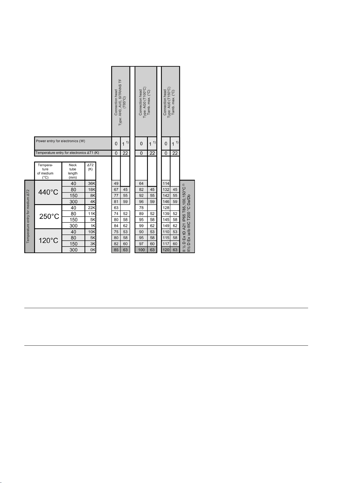
Potentially explosive gases - temperature classes T6, T4, T3
Calculation of the maximum permissible ambient temperatures for the electronics
Calculation of the maximum permissible ambient temperatures for the connection head
● Decontamination declaration (http://www.siemens.com/sc/declarationofdecontamination)
With this declaration you warrant "that the device/replacement part has been carefully cleaned and is free of residues.
The device/replacement part does not pose a hazard for humans and the environment."
If the returned device/replacement part has come into contact with poisonous, corrosive, flammable or water-
contaminating substances, you must thoroughly clean and decontaminate the device/replacement part before returning it
in order to ensure that all hollow areas are free from hazardous substances. Check the item after it has been cleaned.
Any devices/replacement parts returned without a decontamination declaration will be cleaned at your expense before
further processing.
The forms can be found on the Internet as well as in the documentation which comes with the device.
Devices identified by this symbol may not be disposed of in the municipal waste
disposal services under observance of the Directive 2002/96/EC on waste electronic
and electrical equipment (WEEE).
They can be returned to the supplier within the EC or to a locally approved disposal
service. Observe the specific regulations valid in your country.
Storage -40 ... +80 °C (-40 ... +176 °F)
SITRANS TS100 temperature sensors are only approved for the temperature classes T4 and T6. Pay attention to the
temperature resistance of the connection cables.
Potentially explosive gases - temperature classes T6, T4, T3 (Page 22)
Flammable dusts (Page 24)
The maximum permissible ambient temperature T
the respective certificate minus the thermal value ΔT2 from the following table.
for the certified electronics used is calculated from the value present in
amb
The maximum ambient temperatures T
cells in the following table while taking into account the corresponding temperature of the medium.
SITRANS TSinsert/TS100/TS200/TS300/TS500
22 A5E32897051-01, 09/2013
for the respective connection head without electronics can be obtained from the
amb

Tables
The following table contains the maximum permissible ambient temperatures in potentially explosive gas atmospheres in the
connection area of a SITRANS TS500 temperature sensor.
SITRANS TSinsert/TS100/TS200/TS300/TS500
A5E32897051-01, 09/2013
23
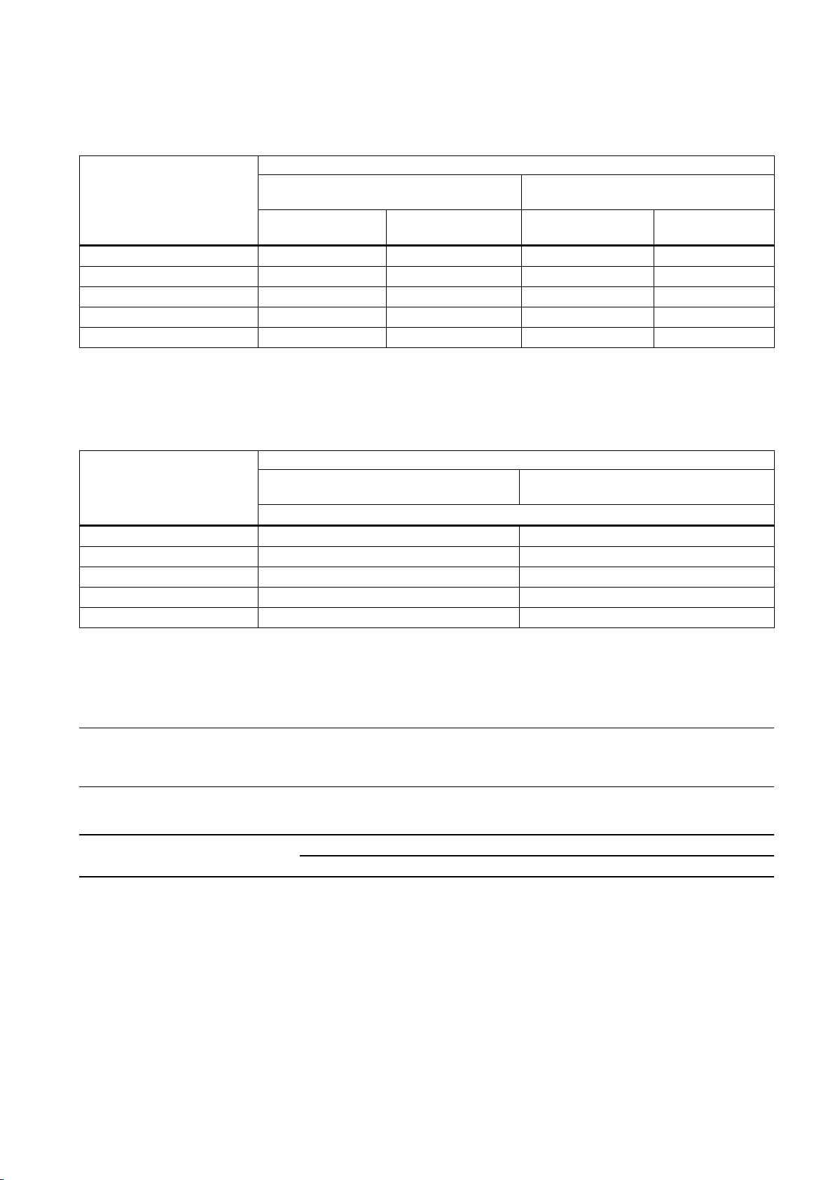
Flammable dusts
ambient temperature.
IECEx Certificate of Conformity IECEx PTB 10.0018X issue No.: 0.
8.1.2
Maximum permitted sample temperatures within the process
Note
Permissible ambient temperature at sensor
The maximum permissible ambient temperature at the sensor simultaneously corresponds to the highest permissible sample
See also
The following table contains the maximum permissible ambient temperatures in areas with combustible dust in the
connection area of a SITRANS TS500 temperature sensor.
1)
Due to the electronics used, a maximum enclosure temperature of 85 °C is used as the basis for determining the
2)
In accordance with EC type examination certificate PTB 10 ATEX 1005 X or
temperature.
The minimum permissible sample temperatures are up to -200 °C depending on the version of the temperature sensor.
Maximum permitted sample temperatures within the process (Page 24)
SITRANS TSinsert/TS100/TS200/TS300/TS500
24 A5E32897051-01, 09/2013
Resistance thermometers
1 x Pt100 TF/3 mm/6 mm
2 x Pt100 TF/3 mm/6 mm
1 x Pt100 WW/3 mm/6 mm
2 x Pt100 WW/3 mm/6 mm
Max. permissible sample temperature (°C)
Certified transmitter in Zone 0 with type of
protection "Intrinsically safe"
Certified transmitter in Zone 1, 2 with type
of protection "Intrinsically safe"
P0: 0 … ≤37 mW 1)
P0: ≥37 … ≤100 mW
P0: 0 … ≤37 mW 1)
P0: ≥37 … ≤100
mW
Thermocouples
1 x TC type J, K, N /3 mm
2 x TC type J, K, N /3 mm
1 x TC type J, K, N /6 mm
2 x TC type J, K, N /6 mm
Max. permissible sample temperature (°C)
Certified transmitter in Zone 0 with type of
protection "Intrinsically safe"
Certified transmitter in Zone 1, 2 with type
of protection "Intrinsically safe"
P0: 0 … 100 mW
8.1.3
Measuring range
Note
Measuring ranges
8.2
Construction
Table 8-1 Pt 100 temperature sensor (Rth max=120 K/W)
T1 = 450 °C -10K 348 340 436 428
T2 = 300 °C -10K 228 220 286 278
T3 = 200 °C - 5K 152 144 191 183
T4 = 135 °C - 5K 100 92 126 118
T6 = 85 °C - 5K 60 52 76 68
1)
e.g. SIEMENS SITRANS TH100/TH200/TH300/TH400
Table 8-2 Thermocouple temperature sensor (Rth max=15 K/W)
T1 = 450 °C -10K 351 439
T2 = 300 °C -10K 231 289
T3 = 200 °C -5K 155 194
T4 = 135 °C -5K 103 129
T6 = 85 °C -5K 63 79
The measuring range refers to the temperature limits in which the thermometer can be used practically for measuring
purposes. Depending on the loads at the place if use and the required accuracies, the actual measuring range may
decrease.
The application or possible operating temperatures depend on the configuration of the temperature sensor.
Torque for cable gland union nut
made of
Plastic Metal Stainless steel
2.5 Nm (1.8 ft lb) 4.2 Nm (3.1 ft lb) 4.2 Nm (3.1 ft lb)
SITRANS TSinsert/TS100/TS200/TS300/TS500
A5E32897051-01, 09/2013
25

8.3
Electrical data
Devices for general use
Measured current
Devices in explosion-protected version
Equipment protection by means of intrinsic safety
SITRANS TSInsert/TS100/TS200
SITRANS TS500
Device protection through type of protection "nA"
Device protection through flame-proof enclosure
8.4
Measuring tolerances for resistance thermometers
Tolerance classes
Tolerance class
Precision
∆t
Tolerances
I
0,3 ... 1.0 mA
Measuring
Type of protection "Intrinsically safe", Zone 20 II 1D Ex ia IIIC T 200°C Da
Type of protection "Intrinsically safe", Zone 0 II 1G Ex ia IIC T6 / T4...T1 Ga
Type of protection "Intrinsically safe", Zone 2 II 3G Ex ic IIC T6 / T4...T1 Gc
Type of protection "Intrinsically safe", Zone 20/21/22 II 1/2D Ex ia/ib IIIC T 200°C Da/Db
Type of protection "Intrinsically safe", Zone 0/1 II 1/2G Ex ia/ib IIC T6 / T4...T1 Ga/Gb
Type of protection "Intrinsically safe", Zone 2 II 3G Ex ic IIC T6 / T4...T1 Gc
For connecting to circuits with the following peak values Ui ≤ 30 V
Type of protection "Non-incendive", Zone 2 II 3G Ex nA IIC T6 / T4…T1 Gc
For connecting to circuits with the following peak values Un = 30 V
1)
Maximum safety voltage
II 1/2 G Ex d IIC T6, T4, T3 Ga/Gb
For connecting to circuits with the following peak values U
≤ 100 mA
I
i
P
= Po (transmitter)
i
= 700 pF/m
C
i
L
= 15 µH/m
i
= 32 V 1)
U
max
II 1/2 D Ex tb IIIC T85 °C,100°C , or 150°C
= 45 V
max
P = 25/37/50/100 mW
The tolerance classes of the resistance thermometers are defined as follows in accordance with IEC 60751:
Class B Basic accuracy ±(0.30 °C +0.0050|t[°C]|)
±1.8x0.30 °F +0.0050x|t[°F]-32|
Class A Increased accuracy ±(0.15 °C +0.0020|t[°C]|)
±1.8x0.15 °F +0.0020x|t[°F]-32|
Class AA (1/3 B) High accuracy ±(0.10 °C +0.0017|t[°C]|)
±1.8x0.10 °F +0.0017x|t[°F]-32|
The following tables provide an overview of the validity ranges of these tolerances. When you use a thermometer above the
specified limits, the values of the next lower accuracy class apply.
SITRANS TSinsert/TS100/TS200/TS300/TS500
26 A5E32897051-01, 09/2013

Action
Tolerance
Precision
Range [°C (°F)]
8.5
Measuring accuracy for thermocouples
Tolerance classes
Catalog versions
Type
Basic accuracy, Class 2
Increased accuracy, Class 1
Further base thermocouples
Type
Basic accuracy, Class 2
Increased accuracy, Class 1
Further noble thermocouples
Type
Basic accuracy, Class 2
Increased accuracy, Class 1
Basic version Class B Basic accuracy -50 ...400 (-58 ... +752)
Class A Increased accuracy -30°... 300 (-58 ... +572)
Class AA (1/3 B) High accuracy 0°... 150 (32 ... 302)
With increased
vibration resistance
With extended
measuring range
The tolerance classes of the thermocouples are defined in the following table in accordance with IEC 584/DIN EN 60584:
Class B Basic accuracy -50°... 400 (-58 ... +752)
Class A Increased accuracy -30°... 300 (-58 ... +662)
Class AA (1/3 B) High accuracy 0°... 150 (32 ... 302)
Class B Basic accuracy -196 ... 600 (392 ... 1112)
Class A Increased accuracy -196 ... 600 (392 ... 1112)
N -40 °C ... +333 °C ±2.5 °C
(-40 °F ... +631 °F ±4.5 °F)
333 °C ... 1100 °C ±0.0075x|t[°C]|
(631 °F ... 2012 °F ±0.0075x|t[°F]-32|)
K -40 °C ... +333 °C ±2.5°C
(-40 °F... +631 °F ±4.5 °F)
333 °C ... 1000 °C ±0.0075x|t[°C]|
(631 °F ... 1832 °F ±0.0075x|t[°F]-32|)
J -40 °C ... +333 °C ±2.5 °C
(-40 °F ... +631 °F ±4.5 °F)
333 °C ... 750 °C ±0.0075x|t[°C]|
(631 °F ... 1382 °F ±0.0075x|t[°F]-32|)
T -40 °C ... +133 °C ±1 °C
(-40 °F ... +271 °F ±1.8 °F)
133 °C ... 350 °C ±0.0075x|t[°C]|
(271 °F ... 662 °F ±0.0075x|t[°F]-32|)
E -40 °C ... +333 °C ±2.5°C
(-40 °F... +631 °F ±4.5 °F)
333 °C ... 900 °C ±0.0075x|t[°C]|
(631 °F ... 1652 °F ±0.0075x|t[°F]-32|)
-40 °C ... +375 °C ±1.5 °C
(-40 °F ... +707 °F ±2.7 °F)
375 °C ... 1000 °C ±0.004x|t[°C]|
(707 °F ... 1832 °F ±0.004x|t[°F]-32|)
-40 °C ... +375 °C ±1.5 °C
(-40 °F... +707 °F ±2.7 °F)
375 °C ... 1000 °C ±0.004x|t[°C]|
(707 °F ... 1832 °F ±0.004x|t[°F]-32|)
-40 °C ... +375 °C ±1.5 °C
(-40 °F ... +707 °F ±2.7 °F)
375 °C ... 750 °C ±0.004x|t[°C]|
(707 °F ... 1382 °F ±0.004x|t[°F]-32|)
-40 °C ... +125 °C ±0.5 °C
(-40 °F ... +257 °F ±0.9 °F)
125 °C ... 350 °C ±0.004x|t[°C]|
(257 °F ... 662 °F ±0.004x|t[°F]-32|)
-40 °C ... +375 °C ±1.5 °C
(-40 °F... +707 °F ±2.7 °F)
375 °C ... 800 °C ±0.004x|t[°C]|
(707 °F ... 1472 °F ±0.004x|t[°F]-32|)
R,S 0 °C ... 600 °C ±1.5 °C
(32 °F ... +1112 °F ±2.7 °F)
600 °C ... 1600 °C ±0.0025x|t[°C]|
(1112 °F ... 2912 °F ±0.0025x|t[°F]-32|)
B 600 °C ... 1700 °C ±0.0025x|t[°C]|
(1112 °F ... 3092 °F ±0.0025x|t[°F]-32|)
SITRANS TSinsert/TS100/TS200/TS300/TS500
A5E32897051-01, 09/2013
0 °C ... 1100 °C ±1 °C
(32 °F ... +2012 °F ±1.8 °F)
1100 °C ... 1600 °C ±[1 + 0.003 x(t -1100)] °C
(2012 °F ... 2912 °F ±1,8+0,003x(t[°F]-2012)
-
27

9
Dimension drawings
9.1
Overview
Versions
Description
● SITRANS TS100 (Page 30)
Versions
Description
Versions
Description
Versions
Description
The following tables contain brief descriptions of the temperature sensors as well as references to the corresponding
dimensional drawings.
Table 9-1 Overview of SITRANS TS100 dimensional drawings
Basic version
Mineral-insulated cable
Table 9-2 Overview of SITRANS TS200 dimensional drawings
Basic sensor, flying leads, LEMO 1S
coupling, M12, thermocouple coupling,
mini connection head
Table 9-3 Overview of SITRANS TS300 dimensional drawings
Modular design with a wide range of
process connections for hygienic
applications
Clamp-on design with collar, strap, or
hook mounting, integrated transmitter
or head
● Temperature sensors in cable design, for universal use, plastic-insulated
version, for unfavorable space conditions.
● SITRANS TS100 (Page 30)
● Temperature sensors in cable design, for universal use, mineral-insulated
version, for unfavorable space conditions.
● Temperature sensors in cable design, for universal use, mineral-insulated
version, for unfavorable space conditions.
● SITRANS TS200 (Page 31)
● Temperature sensors for pipe and vessels in a hygienic application.
● Design according EHEDG
● SITRANS TS300 (Page 32)
● Clamp-on temperature sensor particulary for satured steam sterilization.
● SITRANS TS300 (Page 32)
Table 9-4 Overview of SITRANS TS500 dimensional drawings
Type 2, pipe version without process
connection
Type 2N, pipe version with screw-in
nipple
Type 2G, pipe version with screw-in
nipple and extension
SITRANS TSinsert/TS100/TS200/TS300/TS500
28 A5E32897051-01, 09/2013
● Temperature sensors for containers and pipelines, pipe version for low to
medium stress, without process connection, without extension, for plugging-in
or use with sliding compression joints
● SITRANS TS500, types 2 and 2N (Page 35)
● Temperature sensors for containers and pipelines, pipe version for low to
medium stress, protective tube type 2N similar to DIN 43772, for screwing-in,
without extension, for process temperatures up to 100 °C (212°F)
● SITRANS TS500, types 2 and 2N (Page 35)
● Temperature sensors for containers and pipelines, pipe version for low to
medium stress, protective tube in accordance with DIN 43772, type 2G, for
screwing-in, with extension
● SITRANS TS500, types 2G and 2F (Page 36)

Versions
Description
● SITRANS TS500, types 4 and 4F (Page 39)
Versions
Description
Type 2F, pipe version with flange and
extension
Type 3, fast pipe version without
process connection
Type 3G, fast pipe version with screwin nipple and extension
Type 3F, fast pipe version with flange
and extension
Types 4 and 4F, full material version,
with extension
SITRANS TS500 for installation in
existing protective tubes
● Temperature sensors for containers and pipelines, pipe version for low to
medium stress, protective tube in accordance with DIN 43772, type 2F, with
flange, with extension
● SITRANS TS500, types 2G and 2F (Page 36)
● Temperature sensors for containers and pipelines, pipe version for low to
medium stress, without process connection, without extension, for plugging-in
or use with sliding compression joints
● SITRANS TS500, type 3 (Page 37)
● Temperature sensors for containers and pipelines, pipe version for low to
medium stress, protective tube in accordance with DIN 43772,
type 3G, for screwing-in, without process connection, with extension
● SITRANS TS500, types 3G and 3F (Page 38)
● Temperature sensors for containers and pipelines, pipe version for low to
medium stress, protective tube in accordance with DIN 43772, type 3F, with
flange, with extension
● SITRANS TS500, types 3G and 3F (Page 38)
● Temperature sensors for containers and pipelines, full material version for
medium to very high stress, protective tube in accordance with DIN 43772,
type 4, for welding-in, with extension
● Protective tube type 4F, with flange, with extension
● Temperature sensors for containers and pipelines, temperature sensors for
installation in existing protective sleeves, suitable for sleeves in accordance
with DIN 43772 and ASME B40.9-2001, with extension of European or
American design
● SITRANS TS500 for installation in existing protective tubes (Page 40)
Table 9-5 Overview of SITRANS TSinsert dimensional drawings: measuring inserts for retrofitting and upgrading
European design
● Measuring inserts for temperature sensors, replaceable, mineral-insulated
version, European design (DIN ceramic base),
spring approx. 8 mm (0.31 inch)
● SITRANS TSinsert - measuring inserts for SITRANS TS500 (Page 41)
American design
● Measuring inserts for temperature sensors, replaceable, mineral-insulated
version, American design, spring approx. 25 mm (0.98 inch)
● SITRANS TSinsert - measuring inserts for SITRANS TS500 (Page 41)
SITRANS TSinsert/TS100/TS200/TS300/TS500
A5E32897051-01, 09/2013
29
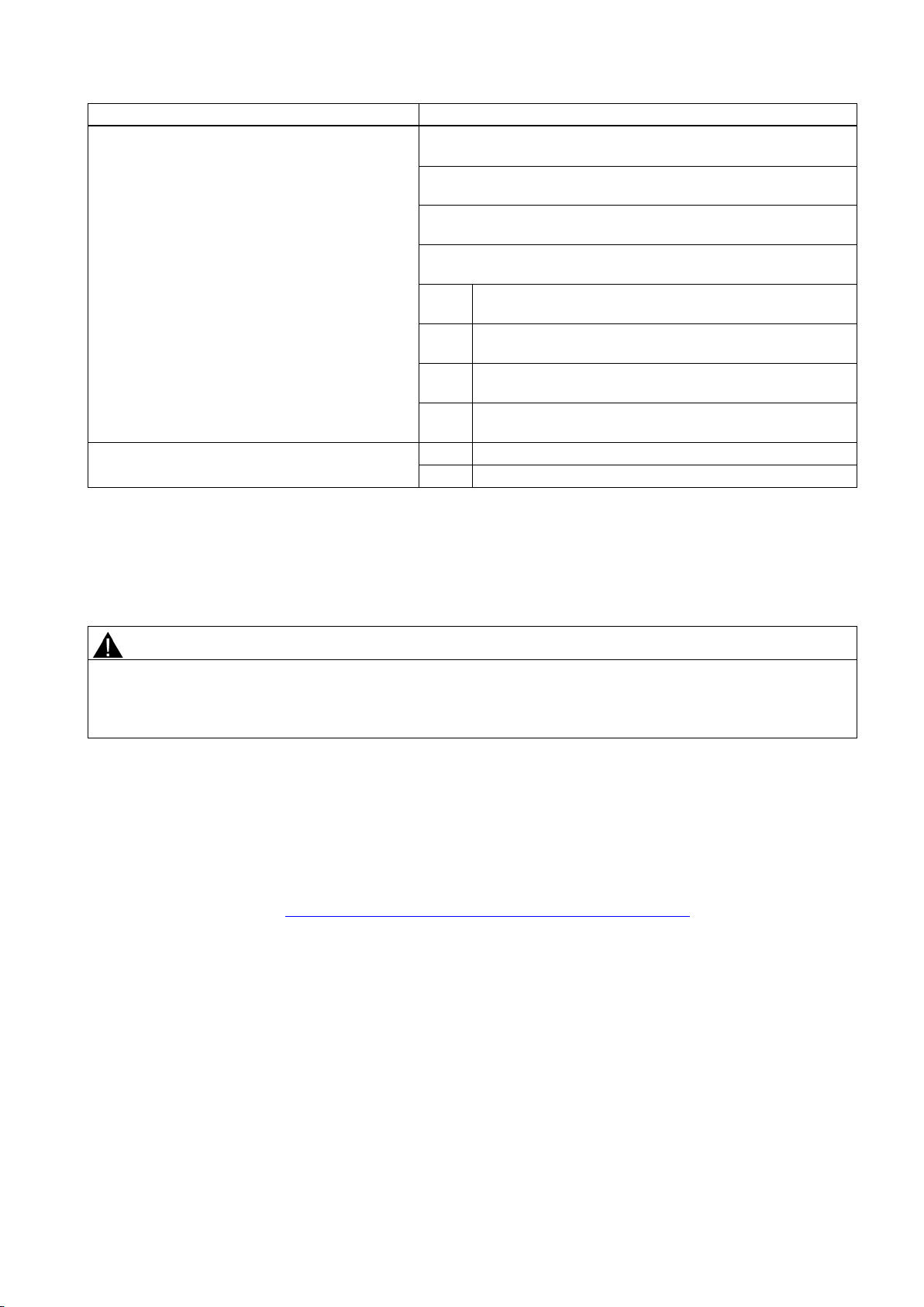
9.2
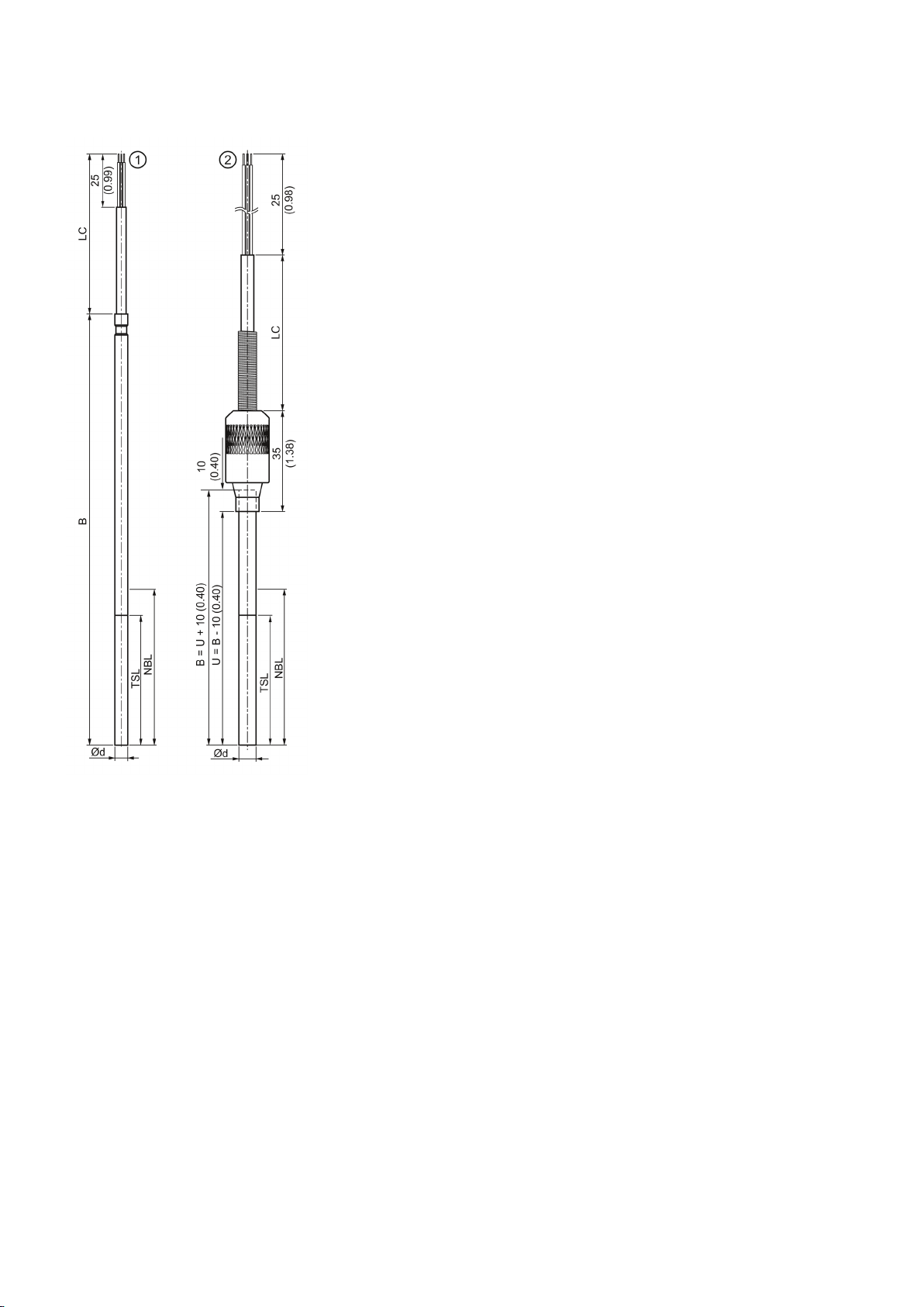
SITRANS TS100
dimensions in
①
②
∅d External diameter of measuring insert (6 (0.24))
B Length of measuring insert
LC Cable length
NBL Non bendable length
TSL Temperature sensitive length
U Mounting length
TS100 basic version
TS100 mineral-insulated version
Dimensional drawings SITRANS TS100 mm (inch)
SITRANS TSinsert/TS100/TS200/TS300/TS500
30 A5E32897051-01, 09/2013
 Loading...