

Siemens SITRANS TH400 PROFIBUS PA Configuration Manual

Introduction
1
The Physical Block
(PA Slot 0), PROFIBUS
2
The Transducer Block
3
Analogue Input Blocks,
PROFIBUS
4
SITRANS T
Temprature measuring instruments
SITRANS TH400 PROFIBUS PA
Configuration Manual
02/2007
A5E01039143-01

Safety Guidelines
This manual contains notices you have to observe in order to ensure your personal safety, as well as to prevent
damage to property. The notices referring to your personal safety are highlighted in the manual by a safety alert
symbol, notices referring only to property damage have no safety alert symbol. These notices shown below are
graded according to the degree of danger.
Danger
indicates that death or severe personal injury will result if proper precautions are not taken.
Warning
indicates that death or severe personal injury may result if proper precautions are not taken.
Caution
with a safety alert symbol, indicates that minor personal injury can result if proper precautions are not taken.
Caution
without a safety alert symbol, indicates that property damage can result if proper precautions are not taken.
Notice
indicates that an unintended result or situation can occur if the corresponding information is not taken into
account.
If more than one degree of danger is present, the warning notice representing the highest degree of danger will
be used. A notice warning of injury to persons with a safety alert symbol may also include a warning relating to
property damage.
Qualified Personnel
The device/system may only be set up and used in conjunction with this documentation. Commissioning and
operation of a device/system may only be performed by qualified personnel. Within the context of the safety notes
in this documentation qualified persons are defined as persons who are authorized to commission, ground and
label devices, systems and circuits in accordance with established safety practices and standards.
Prescribed Usage
Note the following:
Warning
This device may only be used for the applications described in the catalog or the technical description and only in
connection with devices or components from other manufacturers which have been approved or recommended by
Siemens. Correct, reliable operation of the product requires proper transport, storage, positioning and assembly
as well as careful operation and maintenance.
Trademarks
All names identified by ® are registered trademarks of the Siemens AG. The remaining trademarks in this
publication may be trademarks whose use by third parties for their own purposes could violate the rights of the
owner.
Disclaimer of Liability
We have reviewed the contents of this publication to ensure consistency with the hardware and software
described. Since variance cannot be precluded entirely, we cannot guarantee full consistency. However, the
information in this publication is reviewed regularly and any necessary corrections are included in subsequent
editions.
Siemens AG
Automation and Drives
Postfach 48 48
90437 NÜRNBERG
GERMANY
A5E01039143-01
Ⓟ 02/2007
Copyright © Siemens AG2007.
Technical data subject to change

SITRANS TH400 PROFIBUS® PA
Configuration Manual, 02/2007, A5E01039143-01
3
Table of contents
1 Intorduction................................................................................................................................................ 5
2 The Physical Block (PA Slot 0), PROFIBUS .............................................................................................. 7
2.1 Diagnosis .......................................................................................................................................7
2.2 Diagnosis of the Device Characteristics ........................................................................................7
2.3 Physical Block (PA Slot 0) Parameter List, Profibus......................................................................8
3 The Transducer Block.............................................................................................................................. 10
3.1 Transducer Block .........................................................................................................................10
3.2 The data of the Transducer Block Parameter List .......................................................................11
3.3 Default configuration ....................................................................................................................12
3.4 Your application set up. ...............................................................................................................12
3.5 AI_Transducer Block Configuration Flowchart.............................................................................13
3.6 Transducer Block Examples Setup..............................................................................................16
3.6.1 Measurement of RTD with one sensor: .......................................................................................16
3.6.2 Measurement of RTD with two sensors:......................................................................................16
3.6.3 Measurement of thermocouple with one sensor:.........................................................................16
3.6.4 Measurement of thermocouple with two sensors: .......................................................................17
3.6.5 Measurement of combined sensors (Sensor 1 = TC and Sensor 2 = RTD):...............................18
3.6.6 Measurement of resistance (linear) with one sensor:..................................................................18
3.6.7 Measurement of resistance (linear) with two sensors:.................................................................19
3.6.8 Measurement of potentiometer (linear) with one sensor: ............................................................19
3.6.9 Measurement of potentiometer (linear) with two sensors:...........................................................20
3.6.10 Measurement of voltage (linear) with one sensor:.......................................................................20
3.6.11 Measurement of voltage (linear) with two sensors: .....................................................................21
3.6.12 Measurement of 2 potentiometers (with Linear interpolation linearisation): ................................21
3.6.13 Measurement of TC (with Custom Polynomial Linearisation) on sensor 1..................................23
3.7 AI_Transducer and PR_CUST_LIN Block, Schematic.................................................................25

Table of contents
SITRANS TH400 PROFIBUS® PA
4 Configuration Manual, 02/2007, A5E01039143-01
3.8 AI_TRANSDUCER Block (PA Slot 3) Parameter List ................................................................. 25
3.8.1 Sensor characterising parameters .............................................................................................. 26
3.8.2 RTD / Resistor specific parameters ............................................................................................ 28
3.8.3 Thermocouple specific parameters............................................................................................. 29
3.8.4 Output conditioning parameters.................................................................................................. 30
3.8.5 Output parameters ...................................................................................................................... 31
3.8.6 Diagnostic parameters ................................................................................................................ 32
3.8.7 Sensor error detection parameters ............................................................................................. 33
3.8.8 Sensor calibration, Description ................................................................................................... 34
3.8.9 Sensor Calibration Parameters................................................................................................... 35
3.9 PR_CUST_LIN Block (PA Slot 4) Parameter List ....................................................................... 36
3.9.1 Linear interpolation linearisation, Description ............................................................................. 36
3.9.2 Linear Interpolation Linearisation, Parameter List. ..................................................................... 36
3.9.3 Custom Polynomial Linearisation, Description............................................................................ 39
3.9.4 Custom Polynomial Linearisation, Parameter List ...................................................................... 40
3.10 PR_CUST_PRIV Block (PA Slot 5) Reserved Parameter List .................................................... 41
3.10.1 Description, PR_CUST_PRIV Block ........................................................................................... 41
4 Analogue Input Blocks, PROFIBUS......................................................................................................... 43
4.1 Analogue Input Blocks Overview, PROFIBUS............................................................................ 43
4.2 Analogue Input Blocks (PA Slot 1 & 2) Parameter List, PROFIBUS .......................................... 45

SITRANS TH400 PROFIBUS® PA
Configuration Manual, 02/2007, A5E01039143-01
5
Introduction
1
This configuration manual
contains the necessary information for configuration of the temperature transmitter
SITRANS TH400 via a host system with application software for or PROFIBUS
®
PA.
Operation/control with SIMATIC PDM
For the connection setup to SITRANS TH400 PROFIBUS PA the control system SIMATIC
PDM requires:
• the device-specific device data file GSD and
• the Device Description Language file DDL
If you want to use SITRANS TH400 PA in other host systems you can find the GSD-file and
DDL-files:
• on the CD: „SITRANS T - transmitter for temperature“ (A5E00364512), which may be
ordered separately.
• On the Internet
http://www.siemens.com/sitranst
Parameter lists abbreviations
In the Store column:
• SRC = Static Revision Counter; N = No; D = Dynamic;
• Cst = Constant. The parameter doesn’t change in a device.
In the RO / R/W column:
• RO = Read Only; R /W = Read Write; * = Mixed of RO and R/W; ** = Don’t care

Introduction
2.1 Diagnosis
SITRANS TH400 PROFIBUS® PA
6 Configuration Manual, 02/2007, A5E01039143-01
Information
The contents of these instructions shall not become part of or modify any prior or existing
agreement, commitment or legal relationship. All obligations on the part of Siemens AG are
contained in the respective sales contract which also contains the complete and solely
applicable warranty conditions. Any statements contained herein do not create new
warranties or modify the existing warranty.
The content reflects the technical status at the time of printing. We reserve the right to make
technical changes in the course of further development.
Siemens Regional Offices
If you need more information or have particular problems which are not covered sufficiently
by the operating instructions, contact your local Siemens Regional Office. You will find the
address of your local Siemens Regional Office on the Internet.
Product information on the Internet
The Programming Manual is an integral part of the companion CD, which may be ordered
separately. In addition, the Programming Manual is available on the Internet on the Siemens
homepage.
On the CD you will also find the technical data sheet containing the ordering data, the Device
Install software for SIMATIC PDM for subsequent installation and the required software.
See also...
Siemens Regional Offices: https://www.siemens.com/processinstrumentation/contacts
Product Information on SITRANS T in the Internet:
http://www.siemens.com/sitranst
Instructions and Manuals;
http://www.siemens.com/processinstrumentation/documentation

The Physical Block (PA Slot 0), PROFIBUS
2.1 Diagnosis
SITRANS TH400 PROFIBUS® PA
Configuration Manual, 02/2007, A5E01039143-01
7
The Physical Block (PA Slot 0), PROFIBUS
2
2.1 Diagnosis
In order to provide some information about the device to the control application and the
human interface, there are diagnosis parameters in the device. The diagnosis parameters
have a bit string data type and there is a mask parameter indicating which diagnosis is
supported by the device.
2.2 Diagnosis of the Device Characteristics
In the Physical block the DIAGNOSIS parameter has the information about the “alerts” into
the device (for instance, device not initialized, power up, factory init, hardware failure, etc).
The DIAGNOSIS_MASK has the diagnosis supported by the device.

The Physical Block (PA Slot 0), PROFIBUS
2.3 Physical Block (PA Slot 0) Parameter List, PROFIBUS
SITRANS TH400 PROFIBUS® PA
8 Configuration Manual, 02/2007, A5E01039143-01
2.3 Physical Block (PA Slot 0) Parameter List, PROFIBUS
Parameter
Rel.
Index
Description Type Store Size R/W Min Max Default
ST_REV 1
Is incremented each time that there is a change in a static
parameter in the physical block.
Unsigned
16
N 2 RO 0
TAG_DESC 2
Tag name of the block. This parameter must be unique in the
configuration.
OCTET_
STRING
SRC 32 R/W "
STRATEGY 3
This can be used to group a Function Block. It is a user supplied
parameter for identification purpose.
Unsigned
16
SRC 2 R/W 0
ALERT_KEY 4 Current state of alarm blocks Unsigned 8 SRC 1 R/W 0
TARGET_MODE 5 Current desired mode of the block. Unsigned 8 SRC 1 R/W -
MODE_BLK 6
A block has static block parameters, that are not changed by the
process. Values are assigned to this parameter during the
configuration or optimisation. The value of ST_REV must increase
by 1 after every change of a static block parameter. This provides a
check of the parameter revision.
DS-37 D 3 RO
Block
specific
ALARM_SUM 7 Current state of the blocks alarms. DS-42 D 8 RO 0,0,0,0
SOFTWARE_REVISION 8 Software revision of the device
VISBLE_
STRING
Cst 16 RO
HARDWARE_REVISION 9 Physical revision of the device.
VISBLE_
STRING
Cst 16 RO
DEVICE_MAN_ID 10 Siemens AG manufacturer identification number.
Unsigned
16
Cst 2 RO 0x006D
DEVICE_ID 11 Manufacturer device number
VISBLE_
STRING
Cst 16 RO
SITRAN
S
TH400
DEVICE_SER_NUM 12 Device serial number
VISBLE_
STRING
Cst 16 RO
DIAGNOSIS 13 Bit string indicating the diagnosis of the device. See Diagnosis
OCTET_
STRING
D 4 RO
DIAGNOSIS_
EXTENSION
14 Not used.
OCTET_
STRING
D 6 RO
DIAGNOSIS_MASK 15 Not used.
OCTET_
STRING
Cst 4 RO
DIAGNOSIS_MASK_
EXTENSION
16 Not used.
OCTET_
STRING
Cst 6 RO
DEVICE_
CERTIFICATION
17 PA device certification
VISBLE_
STRING
Cst 32 RO
WRITE_LOCKING 18
If Locked, no writes from anywhere are allowed, except to clear
WRITE_LOCK. Cyclic block inputs will continue to be updated.
Unsigned
16
N 2 R/W
FACTORY_RESET 19
Factory reset:
1: Restart with default
2506: Restart processor
2712: Recover default address to the device
Unsigned
16
SRC 2 R/W
DESCRIPTOR 20 It is a user supplied description of the block in the application.
OCTET_
STRING
SRC 32 R/W
DEVICE_MESSAGE 21 It is a user supplied Message of the block in the application.
OCTET_
STRING
SRC 32 R/W

The Physical Block (PA Slot 0), PROFIBUS
2.3 Physical Block (PA Slot 0) Parameter List, PROFIBUS
SITRANS TH400 PROFIBUS® PA
Configuration Manual, 02/2007, A5E01039143-01
9
Parameter
Rel.
Index
Description Type Store Size R/W Min Max Default
DEVICE_INSTAL_DATE 22 Date of the device installation.
OCTET_
STRING
SRC 16 R/W
LOCAL_OP_ENA 23 Not Used. Unsigned 8 N 1 R/W 1
IDENT_NUMBER_
SELECT
24
• 0: Profile specific Ident_Number
• 1: Manufacture specific Ident_Number
Unsigned 8 SRC 1 R/W 1
HW_WRITE_PROTECTI 25
Unimplemented
reserved 26-32
Reserved to PNO (PROFIBUS Nutzerorganisation)

The Transducer Block
3.1 Transducer Block
SITRANS TH400 PROFIBUS® PA
10 Configuration Manual, 02/2007, A5E01039143-01
The Transducer Block
3
3.1 Transducer Block
contains all of the manufacturer-specific parameters that define how the SITRANS TH400
Transmitter functions. Selections such as setting of input type, engineering units, defining the
dual functionality when using the dual input, and so forth, are performed in the Transducer
Block.
The transducer block in SITRANS TH400 allows the user to select a large number of
sophisticated functions. Therefore, the configuration of the transmitter must be carried out
with the greatest possible care.

The Transducer Block
3.2 The data of the Transducer Block Parameter List
SITRANS TH400 PROFIBUS® PA
Configuration Manual, 02/2007, A5E01039143-01
11
3.2 The data of the Transducer Block Parameter List
The data of the Transducer Block Parameter List are grouped as follows:
AI_TRANSDUCER Block, chapter 3.8
• Sensor characterising parameters, chapter 3.8.1
• RTD / resistor specific parameters, chapter 3.8.2
• Thermocouple specific parameters, chapter 3.8.3
• Output conditioning parameters, chapter 3.8.4
• Output parameters, chapter 3.8.5
• Diagnostic parameters, chapter 3.8.6
• Sensor error detection parameters, chapter 3.8.7
• Sensor calibration parameters, chapter 3.8.9
PR_CUST_LIN Block, chapter 3.9
• Linear Interpolation Linearisation, , chapter 3.9.2
• Custom Polynomial linearisation, chapter 3.9.4
PR_CUST_PRIV Block, chapter 3.10
• PR_CUST_PRIV Block, chapter 3.10.1
Note
All product-specific parameters are set off in grey background in the TB Parameter List. In
order to configure these parameters, the files mentioned in the introduction must be available
to the application software.

The Transducer Block
3.3 Default configuration
SITRANS TH400 PROFIBUS® PA
12 Configuration Manual, 02/2007, A5E01039143-01
3.3 Default configuration
The default configuration of SITRANS TH400 will suite the customer’s demand in many
cases. The configuration task has thus been reduced considerably.
The individual default configurations are shown in the TB Parameter List, but in short the
default configuration is as follows:
– Pt100 acc. to the standard
EN 60751
(chapter 3.8.1 LIN_TYPE, value 102)
– °C
(chapter 3.8.1 PRIMARY_VALUE_UNIT, value 1001)
– 3-wire connection
(chapter 3.8.2 SENSOR_CONNECTION, value 1)
– Only sensor 1
(chapter 3.8.4 SENSOR_MEAS_TYPE, value 220)
– No sensor error detection
(chapter 3.8.7 SENSOR_WIRE_CHECK_1, value 3)
3.4 Your application set up.
In the Transducer block all parameters marked R / W can be adapted to suit any
measurement in temperature, ohm or mV. The way of presenting the file data mentioned in
the introduction varies greatly from one piece of application software to the other. Some
programs show drop down menus in which the parameters must be selected via text lines,
while other programs require the user to type in the numerical value of the parameter
selection.
The Transducer Block
3.5 AI_Transducer Block Configuration Flowchart
SITRANS TH400 PROFIBUS® PA
Configuration Manual, 02/2007, A5E01039143-01
13
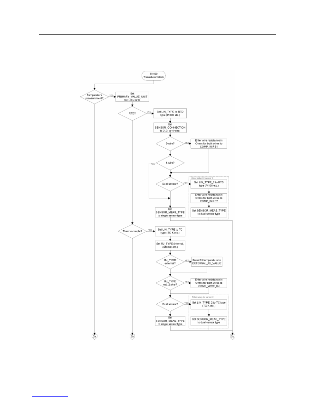
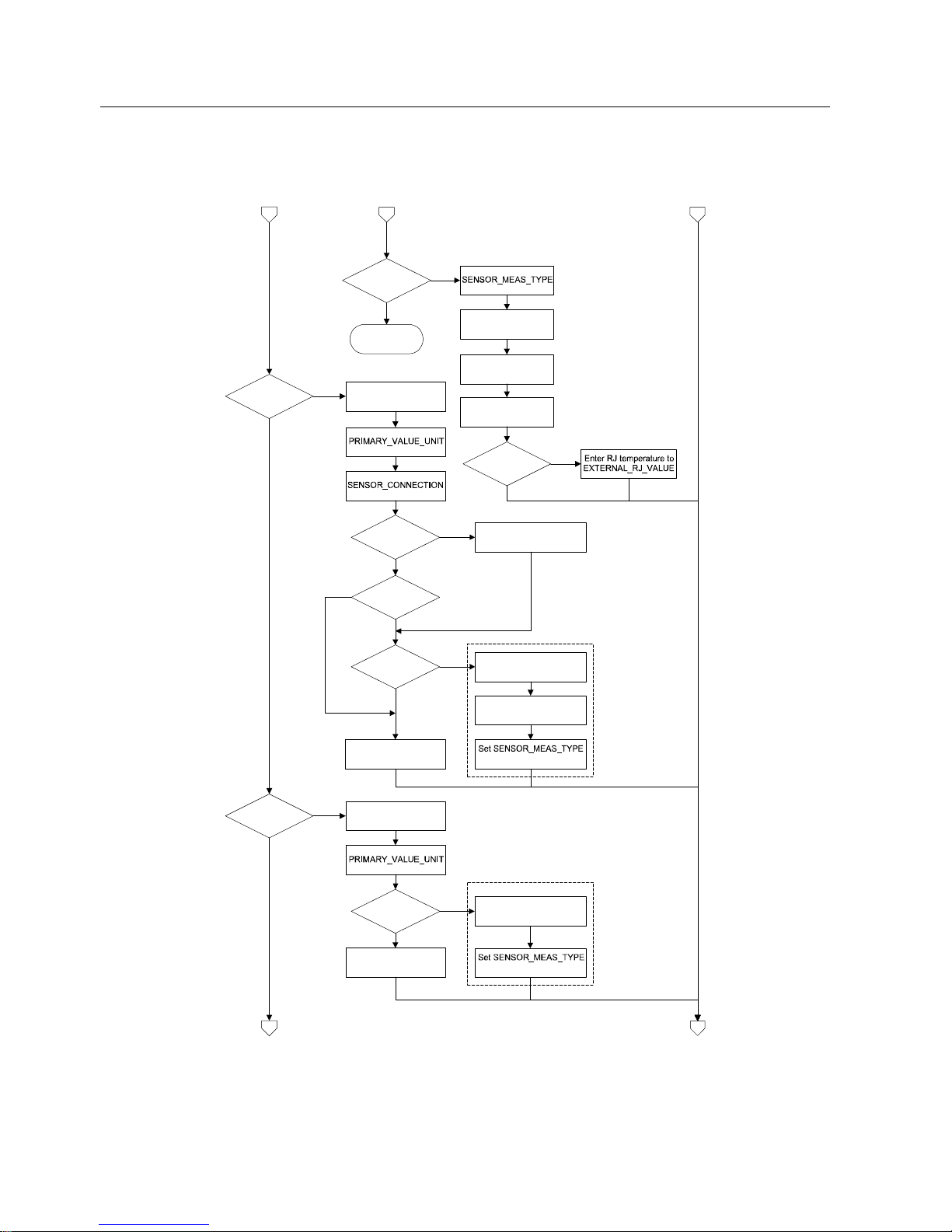
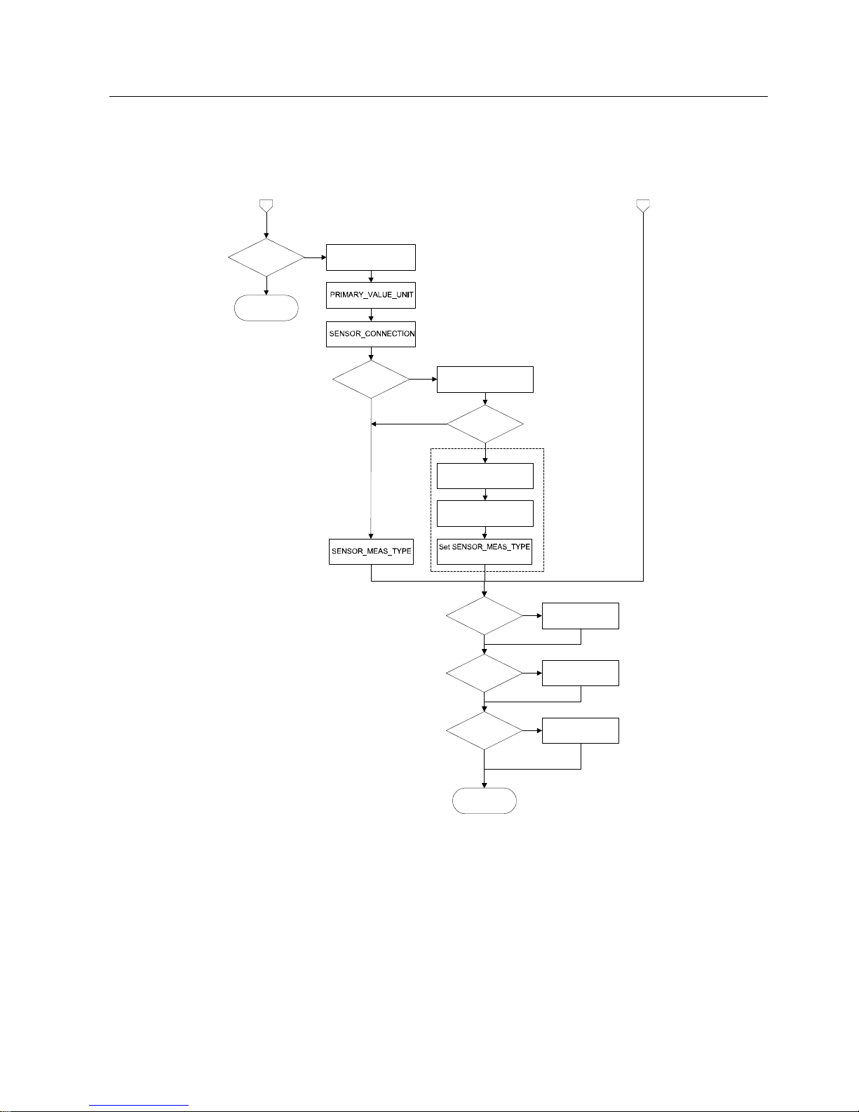
3.5 AI_Transducer Block Configuration Flowchart
The Transducer Block
3.5 AI_Transducer Block Configuration Flowchart
SITRANS TH400 PROFIBUS® PA
14 Configuration Manual, 02/2007, A5E01039143-01
2c
RTD+Thermo-
couple?
2b
Set LIN_TYPE to TC
type (TC K etc.)
Set RJ_TYPE
(internal, external e tc.)
Set
to dual sensor type
Set LI N_TYPE _2 to
RTD type (Pt100 etc.)
RJ_TYPE
external?
YES
YE S
2a
Error! (t ry again)
Resistanc e?
Set
to Ohm or kOhm
Set
to 2-,3-or 4-wire.
Dual sensor?
Enterwire resistance in
Ohms for both wires to
COMP_W IRE1
2-wire?
YES
Entersetup for sensor2 :
YE S
Set LIN_TYPE_2 to
”no linearis ation” or
”linearisation table”
Set
SENSOR_MEAS_TYPE
to single sensor type
Set LIN_TYPE to
”no linearisation” or
”linearisat ion table”
to dual s ensor typ
e
Enterwire resistance in
Ohms for both wires to
COMP_W IRE2
Millivolts?
Set
to V, mV or µV
Set LIN_TYPE to
”no linearisation” or
”linearisat ion table”
Dual sensor?
Set LIN_TYPE_2 to
”no linearisation” or
”linearisat ion table”
Set
SENSOR_MEAS_TYPE
to single sensor type
to dual sens or type
3b3a
Entersetupforsensor2:
YES
YES
YES
4-wire?
YES
The Transducer Block
3.5 AI_Transducer Block Configuration Flowchart
SITRANS TH400 PROFIBUS® PA
Configuration Manual, 02/2007, A5E01039143-01
15
3b3a
Potentiometer?
Set
to ”%”
Set
to 3- or 4-wire.
Enter wire resistance in
Ohms for 2 wires to
COMP_WIRE1
3-wire?
YES
Enter setup
for se nsor 2:
YES
Set LIN_TYPE_2 to
”no linearisation” or
”linearisation table”
Set
to single sensor type
Set LIN_TYPE to
”no linea risation ” or
”linearisation table”
to dual sensor type
Enter wire resistance in
Ohms for 2 wires to
COMP_WIRE2
Error! (try a gain)
Finished.
Transducer block
is configured!
Enter Custom RTD
polynomial values
Linearisation
table?
Custom RTD?
Enter linearisation
table values
YES
YES
Enter Custom TC
polynomial values
Custom TC?
YES
Dual sensor?
YES
 Loading...