

Siemens SITRANS TH400 Operating Instructions Manual

SITRANS TH400
_
_________________
_
_
_________________
_
_
_________________
_
_
_________________
_
_
_________________
_
_
_________________
_
_
_________________
_
_
_________________
_
_
_________________
_
_
_________________
_
_
_________________
_
_
_________________
_
_
__________________
SITRANS T
Temperature transmitter
SITRANS TH400
Operating Instructions
7NG3214 SITRANS TH400 with PROFIBUS PA
7NG3215 SITRANS TH400 with FOUNDATION
fieldbus
06/2010
A5E01018688-02
Introduction
1
General safety notes
2
Description
3
Assembly
4
Connecting
5
Operation
6
Commissioning
7
Functions
8
Service and maintenance
9
Technical data
10
Dimension drawings
11
Spare parts and accessories
12
Appendix
A

Legal information
Legal information
Warning notice system
This manual contains notices you have to observe in order to ensure your personal safety, as well as to prevent
damage to property. The notices referring to your personal safety are highlighted in the manual by a safety alert
symbol, notices referring only to property damage have no safety alert symbol. These notices shown below are
graded according to the degree of danger.
DANGER
indicates that death or severe personal injury will result if proper precautions are not taken.
WARNING
indicates that death or severe personal injury may result if proper precautions are not taken.
CAUTION
with a safety alert symbol, indicates that minor personal injury can result if proper precautions are not taken.
CAUTION
without a safety alert symbol, indicates that property damage can result if proper precautions are not taken.
NOTICE
indicates that an unintended result or situation can occur if the corresponding information is not taken into
account.
If more than one degree of danger is present, the warning notice representing the highest degree of danger will
be used. A notice warning of injury to persons with a safety alert symbol may also include a warning relating to
property damage.
Qualified Personnel
The product/system described in this documentation may be operated only by personnel qualified for the specific
task in accordance with the relevant documentation for the specific task, in particular its warning notices and
safety instructions. Qualified personnel are those who, based on their training and experience, are capable of
identifying risks and avoiding potential hazards when working with these products/systems.
Proper use of Siemens products
Note the following:
WARNING
Siemens products may only be used for the applications described in the catalog and in the relevant technical
documentation. If products and components from other manufacturers are used, these must be recommended
or approved by Siemens. Proper transport, storage, installation, assembly, commissioning, operation and
maintenance are required to ensure that the products operate safely and without any problems. The permissible
ambient conditions must be adhered to. The information in the relevant documentation must be observed.
Trademarks
All names identified by ® are registered trademarks of the Siemens AG. The remaining trademarks in this
publication may be trademarks whose use by third parties for their own purposes could violate the rights of the
owner.
Disclaimer of Liability
We have reviewed the contents of this publication to ensure consistency with the hardware and software
described. Since variance cannot be precluded entirely, we cannot guarantee full consistency. However, the
information in this publication is reviewed regularly and any necessary corrections are included in subsequent
editions.
Siemens AG
Industry Sector
Postfach 48 48
90026 NÜRNBERG
GERMANY
order number: A5E01018688
Ⓟ 10/2010
Copyright © Siemens AG 2010.
Technical data subject to change

SITRANS TH400
Operating Instructions, 06/2010, A5E01018688-02
3
Table of contents
1 Introduction................................................................................................................................................ 5
1.1
Purpos
e of this documentation ......................................................................................................5
1.2 His
tory............................................................................................................................................5
1.3
Notes
on warranty..........................................................................................................................6
1.4
Env
ironmental protection ...............................................................................................................6
2
Gener
al safety notes.................................................................................................................................. 7
2.1 General information
.......................................................................................................................7
2.2
Correc
t usage.................................................................................................................................7
2.3
Qualified Pers
onnel........................................................................................................................7
2.4
Laws
and directives .......................................................................................................................8
2.5
Measures
.......................................................................................................................................9
3
Des
cription............................................................................................................................................... 11
3.1
Summary
......................................................................................................................................11
3.2 Applic
ation range .........................................................................................................................11
3.3
Product features
...........................................................................................................................12
3.4
Ty
pe plate structure .....................................................................................................................12
3.5
Mode of
operation ........................................................................................................................13
3.6 Sy
stem communication................................................................................................................14
4
A
ssembly................................................................................................................................................. 15
4.1
Safety
information ........................................................................................................................15
4.2
Installation in
the connection head ..............................................................................................16
4.3 Ins
tallation on DIN rail and G rail .................................................................................................17
5
Conne
cting .............................................................................................................................................. 19
5.1
Safety
information on connecting up ...........................................................................................19
5.1.1
General safety
information on connecting up ..............................................................................19
5.1.2 Safety
notes when connecting in hazardous areas .....................................................................20
5.2 Connec
tion assignments..............................................................................................................22
5.3
Connec
tion diagrams ...................................................................................................................23
5.4 Bus
connection.............................................................................................................................26
6
Operation
................................................................................................................................................. 27
7
Commis
sioning ........................................................................................................................................ 29

Table of contents
SITRANS TH400
4 Operating Instructions, 06/2010, A5E01018688-02
8 Functions................................................................................................................................................. 31
8.1 Summary..................................................................................................................................... 31
8.2
Dev
ice address ........................................................................................................................... 32
8.2.1
SITRANS TH400 PROFIBUS PA
............................................................................................... 32
8.2.2 SITRANS TH400 FOUNDATION field bus
................................................................................. 32
8.3 Device deli
very condition ............................................................................................................ 33
8.4
Simula
tion mode ......................................................................................................................... 34
8.4.1
Simulation mode in PROFIBUS PA
............................................................................................ 34
8.4.2 Simulation m
ode with FOUNDATION fieldbus............................................................................ 34
9 Servic
e and maintenance ........................................................................................................................ 35
10
Techni
cal data ......................................................................................................................................... 37
11
Dimen
sion drawings ................................................................................................................................ 45
12 Spare part
s and accessories ................................................................................................................... 47
A
Appendix
.................................................................................................................................................. 49
A.1
Certificates
/ EC declaration of conformity.................................................................................. 49
A.2
Control drawing
........................................................................................................................... 50
A.3
Technical support
........................................................................................................................ 53
G
lossary .................................................................................................................................................. 55
I
ndex........................................................................................................................................................ 61

SITRANS TH400
Operating Instructions, 06/2010, A5E01018688-02
5
Introduction
1
1.1 Purpose of this documentation
These instructions contain all information that you will require to commission and use the
device. Read these instructions carefully prior to installation and commissioning. In order to
use the device correctly, first make yourself acquainted with its principle of operation.
The instructions are aimed both at persons mechanically installing the device, connecting it
electronically, configuring the parameters and commissioning it as well as service and
maintenance engineers.
1.2 History
This history establishes the correlation between the current documentation and the valid
firmware of the device.
The documentation of this edition is applicable for the following firmware variants:
Edition Firmware identification type
plate
System integration Installation path for PDM
PROFIBUS PA version:
01
02/2007
02
06/2010
FW: V2.03 PDM V6.0
DD rev. 1.00
SITRANS TH400
FOUNDATION fieldbus version:
01
02/2007
02
06/2010
FW: V2.03 Standard fieldbus
compatible control
systems
Not relevant.
The most important changes in the documentation when compared with the respective
previous edition are given in the following table.
Edition Remarks
01
02/2007
First edition
02
06/2010
Revised safety information, modifications in chapter "Connection"

Introduction
1.3 Notes on warranty
SITRANS TH400
6 Operating Instructions, 06/2010, A5E01018688-02
1.3 Notes on warranty
The contents of this programming manual shall not become part of or modify any prior or
existing agreement, commitment or legal relationship. All obligations on the part of Siemens
AG are contained in the respective sales contract, which also contains the complete and
solely applicable warranty conditions. Any statements on the device versions described in
the programming manual do not create new warranties or modify the existing warranty.
The content reflects the technical status at the time of printing. We reserve the right to make
technical changes in the course of further development.
See also
Instructions and Manuals (http://www.siemens.com/processinstrumentation/documentation)
Product information on SITRANS T in the Internet (http://www.siemens.com/sitranst
)
Contacts (http://www.siemens.com/processinstrumentation/contacts
)
1.4 Environmental protection
Recycling
Devices described in this programming manual can be recycled owing to the low content of
noxious substances in their version.
Please contact a certified waste disposal company for eco-friendly recycling and to dispose
of your old devices.

SITRANS TH400
Operating Instructions, 06/2010, A5E01018688-02
7
General safety notes
2
2.1 General information
This device left the factory free from safety problems. In order to maintain this status and to
ensure safe operation of the device, please observe the safety information and warnings
contained in these instructions.
Safety information and symbols must be observed without exception. They must not be
removed and must be maintained in legible condition at all times.
2.2 Correct usage
The device may only be used for the purposes specified in these instructions.
Insofar as they are not expressly stated in these instructions, all changes to the device are
the sole responsibility of the user.
2.3 Qualified Personnel
Qualified personnel are people who are familiar with the installation, mounting,
commissioning, and operation of the product. These people have the following qualifications:
● They are authorized, trained or instructed in operating and maintaining devices and
systems according to the safety regulations for electrical circuits, high pressures and
aggressive as well as hazardous media.
● For explosion-proof devices: They are authorized, trained, or instructed in carrying out
work on electrical circuits for hazardous systems.
● They are trained or instructed in maintenance and use of appropriate safety equipment
according to the safety regulations.

General safety notes
2.4 Laws and directives
SITRANS TH400
8 Operating Instructions, 06/2010, A5E01018688-02
2.4 Laws and directives
Observe the test certification, provisions and laws applicable in your country during
connection, assembly and operation. These include, for example:
● National Electrical Code (NEC - NFPA 70) (USA)
● Canadian Electrical Code (CEC) (Canada)
● The working reliability regulation (Germany)
Further provisions for hazardous areas, these are for example:
● IEC 60079-14 (international)
● EN 60079-14 (formerly VDE 0165, T1) (EU, Germany)
See also
Certificates (http://www.siemens.com/processinstrumentation/certificates)

General safety notes
2.5 Measures
SITRANS TH400
Operating Instructions, 06/2010, A5E01018688-02
9
2.5 Measures
In the interests of safety, the following precautions must be observed:
WARNING
"Intrinsic safety" type of protection
Connect the device only to certified, intrinsically safe circuits. These circuits must comply
with the technical data specified on the nameplate or in the certificates and approvals.
Should these circuits not match the details given in the certificates and approvals, then the
safety required for the approval can no longer be guaranteed. The device's protection level
"ia" is lowered to protection level "ib" if fail-safe circuits are connected with protection level
"ib".
"Limited energy" type of protection ic/nL (Zone 2)
Devices of the protection type "limited energy" can be connected and disconnected during
operation.
"Non-sparking" type of protection nA (Zone 2)
Devices of the protection type "non-sparking" may only be connected and disconnected
when in a powered-down state.
CAUTION
Modules susceptible to electrical discharge
The device contains modules susceptible to electrical discharge. Modules susceptible to
electrical discharge can be destroyed by voltages that fall far below the limits of human
perception. These voltages even occur if you touch a component part or electrical
connections of a module without being electrostatically discharged. The damage to a
module caused by overvoltage cannot normally be detected immediately, it only becomes
apparent after a longer period of operating time has elapsed.

General safety notes
2.5 Measures
SITRANS TH400
10 Operating Instructions, 06/2010, A5E01018688-02

SITRANS TH400
Operating Instructions, 06/2010, A5E01018688-02
11
Description
3
3.1 Summary
The temperature transmitter SITRANS TH400 is available in to basic versions for the
fieldbus protocols:
● PROFIBUS PA (7NG3214 ...)
● FOUNDATION fieldbus (7NG3215 ...)
3.2 Application range
● Linearized temperature measurement with a resistance thermometer or thermocouple;
● Difference, mean value, or redundant temperature measurement with resistance
thermometer or thermocouple;
● Linear resistance and bipolar millivolt measurements;
● Difference, mean value or redundant resistance and bipolar millivolt measurement.
Install and operate the explosion-proof transmitter in hazardous areas according to the
specifications of the EC-type examination certificate per ATEX and these Operating
Instructions or the inspection certificate valid in your country.
Description
3.3 Product features
SITRANS TH400
12 Operating Instructions, 06/2010, A5E01018688-02
3.3 Product features
● Installation in the type B connection head per DIN 43729 or a larger connection head.
● Transmitter with PROFIBUS PA communication
● Transmitter with FOUNDATION fieldbus communication
● Capable of communication via PROFIBUS PA and FOUNDATION fieldbus. For example,
sensor activation and measuring range can be programmed with it.
● Configuration via PROFIBUS PA with SIMATIC PDM (SITRANS TH400 as PROFIBUS
PA version) or via FOUNDATION fieldbus with Emerson AMS, handheld 375 (SITRANS
TH400 as FOUNDATION fieldbus version).
● The simulation mode in FOUNDATION fieldbus is activated with a magnetic pin.
● Polarity-independent bus connection
● 24 bit analog-to-digital converter for a high resolution
● PROFIBUS PA function blocks: Two analog
● FOUNDATION fieldbus function blocks: Two analog and one PID
● FOUNDATION fieldbus functionality: Basic or LAS.
● Galvanical isolation
● Intrinsically safe version for use in hazardous areas
● Special characteristic curve
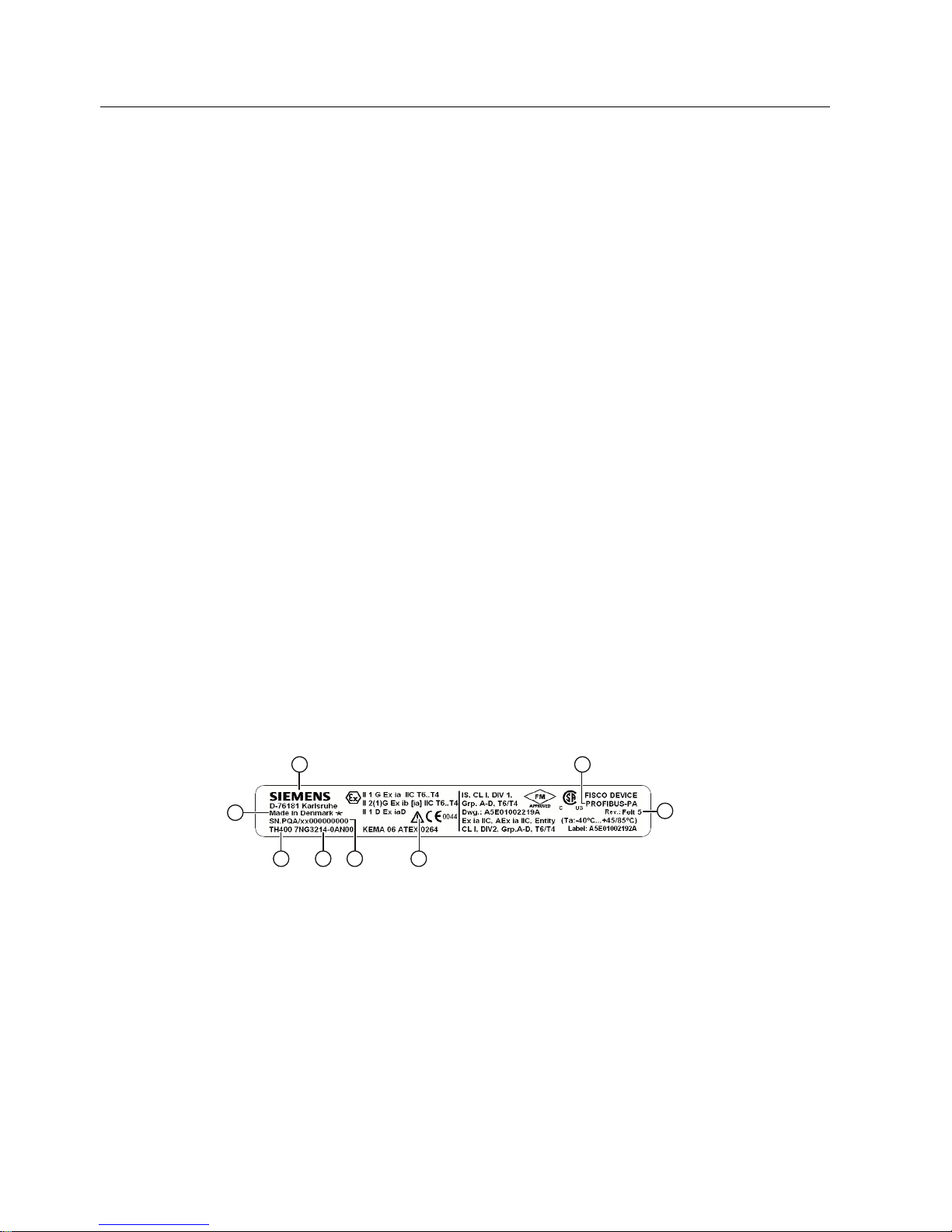
3.4 Type plate structure
The type plate is located on the housing and carries the order number and other important
product information; see following example.
① Manufacturer ② Device version: PROFIBUS PA or
FOUNDATION Fieldbus
③ Hardware and firmware revision ④ Pay attention to the Operating Instructions
⑤ Serial number with coded production year and
production month.
⑥ Order number
⑦ Type designation ⑧ Place of manufacture
Figure 3-1 Example: Type plate
Description
3.5 Mode of operation
SITRANS TH400
Operating Instructions, 06/2010, A5E01018688-02
13
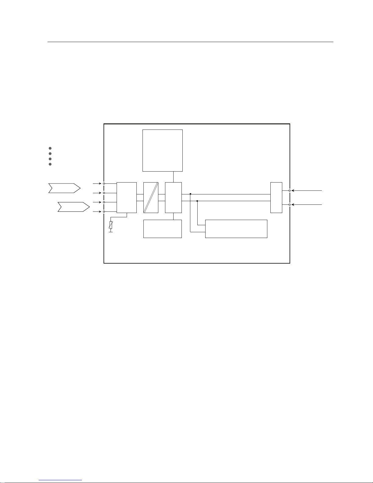
3.5 Mode of operation
In what follows, the mode of operation of the transmitter is explained using the function block
diagram.
The two versions of the SITRANS TH400 (7NG3214 ... and 7NG3215 ...) are distinguished
solely by the type of the fieldbus protocols (PROFIBUS PA or FOUNDATION fieldbus).
6HOHFWDEOHLQSXWV
5HVLVWDQFHWKHUPRPHWHU
7KHUPRFRXSOH
0LOOLYROWWUDQVPLWWHU
5HVLVWDQFHW\SHWUDQVPLWWHU
,QSXW
,QSXW
7UD QV IR UP HU
,QSXW
,QSXW
'LIIHUHQFH
0HDQYDOXH
5HGXQGDQF\
7HUPLQDOWHPSHUDWXUH
(QJLQHHULQJXQLWV
'LDJQRV WLFIXQFW LRQV
7DEOHOLQHDUL]DWLRQ
3RO\QRPLDOOLQHDUL]DWLRQ
3URFHVVFDOLEUDWLRQ
$'
FRQYHU
WHU
&RPSOH[FRQILJXUDWLRQ
&RUUHF WLRQFRH IILF LHQFH
)DFWRU\V HWWLQJV
352),%863 URWRFRO 1*
RU
)RXQGDWLR Q)LHOGEXV3U RWRFRO 1*
%XVFRQQHFWLRQ
([FLUFXLW
(OHFWULF DO
LVRODWLRQ
,QWHUQDO
3W
((3520
&38
.RPPXQLNDWLRQ
Figure 3-2 Function block diagram SITRANS TH400
Description
3.6 System communication
SITRANS TH400
14 Operating Instructions, 06/2010, A5E01018688-02
3.6 System communication
s
2XWSXW
%XV
WHUPLQDWRU
%XV
WHUPLQDWRU
6HJPHQW
FRXSOHU
6HJPHQW
FRXSOHU
%XVFRQQHFWLRQ
%XVFRQQHFWLRQ
352),%863$
)281'$7,21)LHOGEXV
s
6,75$167+))
6,75$167+3$
Figure 3-3 Communications interface

SITRANS TH400
Operating Instructions, 06/2010, A5E01018688-02
15
Assembly
4
4.1 Safety information
CAUTION
Mounting in hazardous areas
Make sure you observe the following information before installing the transmitter:
Install the transmitter in an enclosure appropriate for the envisaged application
In hazardous areas, also observe the requirements specified in the Ex certificates and
approvals.
Comply with the ambient conditions specified in the technical data.
Assembly
4.2 Installation in the connection head
SITRANS TH400
16 Operating Instructions, 06/2010, A5E01018688-02
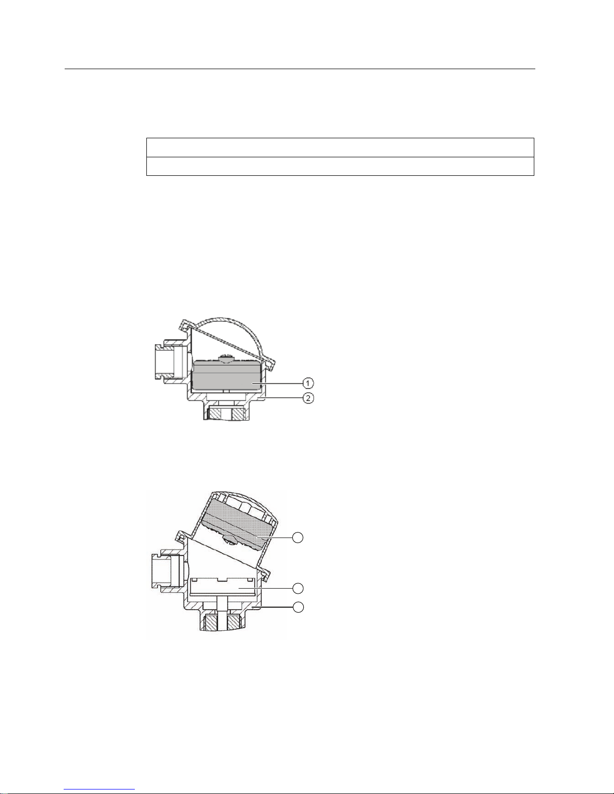
4.2 Installation in the connection head
NOTICE
The transmitter is only designed for installation in a type B connection head or larger.
The transmitter is either secured in the base of the connection head or in the raised cover of
the connection head. Included in the transmitter's scope of delivery are:
● Springs
● Fixing screws
Securing the transmitter in the connection head base
① Transmitter ② Connection head
Securing the transmitter in the connection head cover
① Transmitter ② Ceramic base of the measuring element
③ Connection head
Assembly
4.3 Installation on DIN rail and G rail
SITRANS TH400
Operating Instructions, 06/2010, A5E01018688-02
17
4.3 Installation on DIN rail and G rail
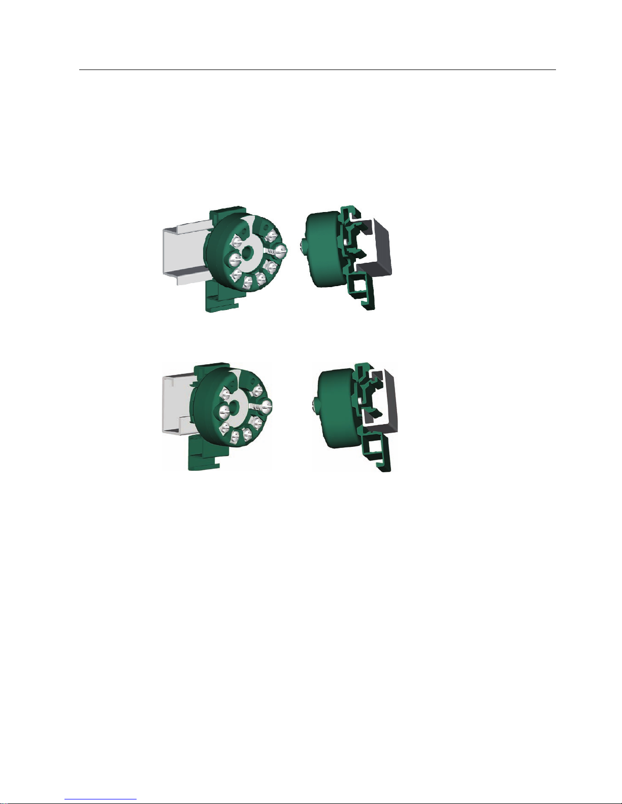
You can either install the transmitter on a DIN rail with 35 mm or on a G rail with 32 mm.
DIN EN 60715 applies to DIN rails and G rails in this context. The DIN rail adapter required
for installation can be ordered as an accessory under the Order No. 7NG3092-8KA.
Adhere to the ambient conditions specified in the technical data.
Figure 4-1 Securing the transmitter on DIN rails
Figure 4-2 Securing the transmitter on G rails

Assembly
4.3 Installation on DIN rail and G rail
SITRANS TH400
18 Operating Instructions, 06/2010, A5E01018688-02

SITRANS TH400
Operating Instructions, 06/2010, A5E01018688-02
19
Connecting
5
5.1 Safety information on connecting up
5.1.1 General safety information on connecting up
Note
National regulations
Be sure to observe the regulations valid and relevant in your country.
Note
To improve the interference immunity:
Lay signal cables separately from cables with voltages > 60 V.
Use cables with twisted wires.
Avoid getting too close to large electrical systems or use shielded cables.
Use shielded cable to guarantee the full specification according to PROFIBUS PA or
FOUNDATION Fieldbus.
Use only cable entries and covers that are approved for the relevant use.
At an ambient temperature T ≥ 60 °C, use heat-resistant cables approved for an ambient
temperature of at least 20 K higher.
Use cables with wires that have a maximum cross-sectional area of 2.5 mm
2
.
See also
Connection diagrams (Page 23)
 Loading...