

Siemens SITRANS TH100, SITRANS TH300, SITRANS TR200, SITRANS TR300, SITRANS TH400 Compact Operating Instructions
...
English ······························································································· 3
Български ························································································ 34
Čeština ····························································································· 66
Suomi······························································································· 97
Slovenčina······················································································· 128
Slovenščina ····················································································· 159
1

Temperature transmitters
SITRANS TH/TR/TF
Compact Operating Instructions
Legal information
Warning notice system
DANGER
indicates that death or severe personal injury will result if proper precautions are not taken.
WARNING
indicates that death or severe personal injury may result if proper precautions are not taken.
CAUTION
indicates that minor personal injury can result if proper precautions are not taken.
NOTICE
indicates that property damage can result if proper precautions are not taken.
Qualified Personnel
personnel qualified
Proper use of Siemens products
WARNING
problems. The permissible ambient conditions must be complied with. The information in the relevant documentation must be observed.
1
Introduction
This manual contains notices you have to observe in order to ensure your personal safety, as well as to prevent damage to property. The
notices referring to your personal safety are highlighted in the manual by a safety alert symbol, notices referring only to property damage
have no safety alert symbol. These notices shown below are graded according to the degree of danger.
If more than one degree of danger is present, the warning notice representing the highest degree of danger will be used. A notice warning of
injury to persons with a safety alert symbol may also include a warning relating to property damage.
The product/system described in this documentation may be operated only by
the relevant documentation, in particular its warning notices and safety instructions. Qualified personnel are those who, based on their
training and experience, are capable of identifying risks and avoiding potential hazards when working with these products/systems.
Note the following:
Siemens products may only be used for the applications described in the catalog and in the relevant technical documentation. If products
and components from other manufacturers are used, these must be recommended or approved by Siemens. Proper transport, storage,
installation, assembly, commissioning, operation and maintenance are required to ensure that the products operate safely and without any
These instructions are a brief summary of important features, functions and safety information, and contain all information
required for safe use of the device. It is your responsibility to read the instructions carefully prior to installation and
commissioning. In order to use the device correctly, first review its principle of operation.
The instructions are aimed at persons who mechanically assemble the device, connect it electrically, and start it up.
To achieve optimum usage of the device, read the detailed version of the manual.
1. Check the packaging and the device for visible damage caused by inappropriate handling during shipping.
2. Report any claims for damages immediately to the shipping company.
3. Retain damaged parts for clarification.
4. Check the scope of delivery by comparing your order to the shipping documents for correctness and completeness.
for the specific task in accordance with
© Siemens AG 2013. All rights reserved
A5E32520700-01, 06/2013
3
WARNING
Using a damaged or incomplete device
● Do not use damaged or incomplete devices.
CAUTION
Insufficient protection during storage
● Provide additional packaging as necessary.
Danger of explosion in hazardous areas.
To guarantee sufficient protection during transport and storage, observe the following:
● Keep the original packaging for subsequent transportation.
● Devices/replacement parts should be returned in their original packaging.
● If the original packaging is no longer available, ensure that all shipments are properly packaged to provide sufficient
protection during transport. Siemens cannot assume liability for any costs associated with transportation damages.
The packaging only provides limited protection against moisture and infiltration.
Special conditions for storage and transportation of the device are listed in "Technical data" (Page 26).
The contents of this manual shall not become part of or modify any prior or existing agreement, commitment or legal
relationship. The sales contract contains all obligations on the part of Siemens as well as the complete and solely applicable
warranty conditions. Any statements regarding device versions described in the manual do not create new warranties or
modify the existing warranty.
The content reflects the technical status at the time of publishing. Siemens reserves the right to make technical changes in
the course of further development.
SITRANS TH/TR/TF
4 A5E32520700-01, 06/2013
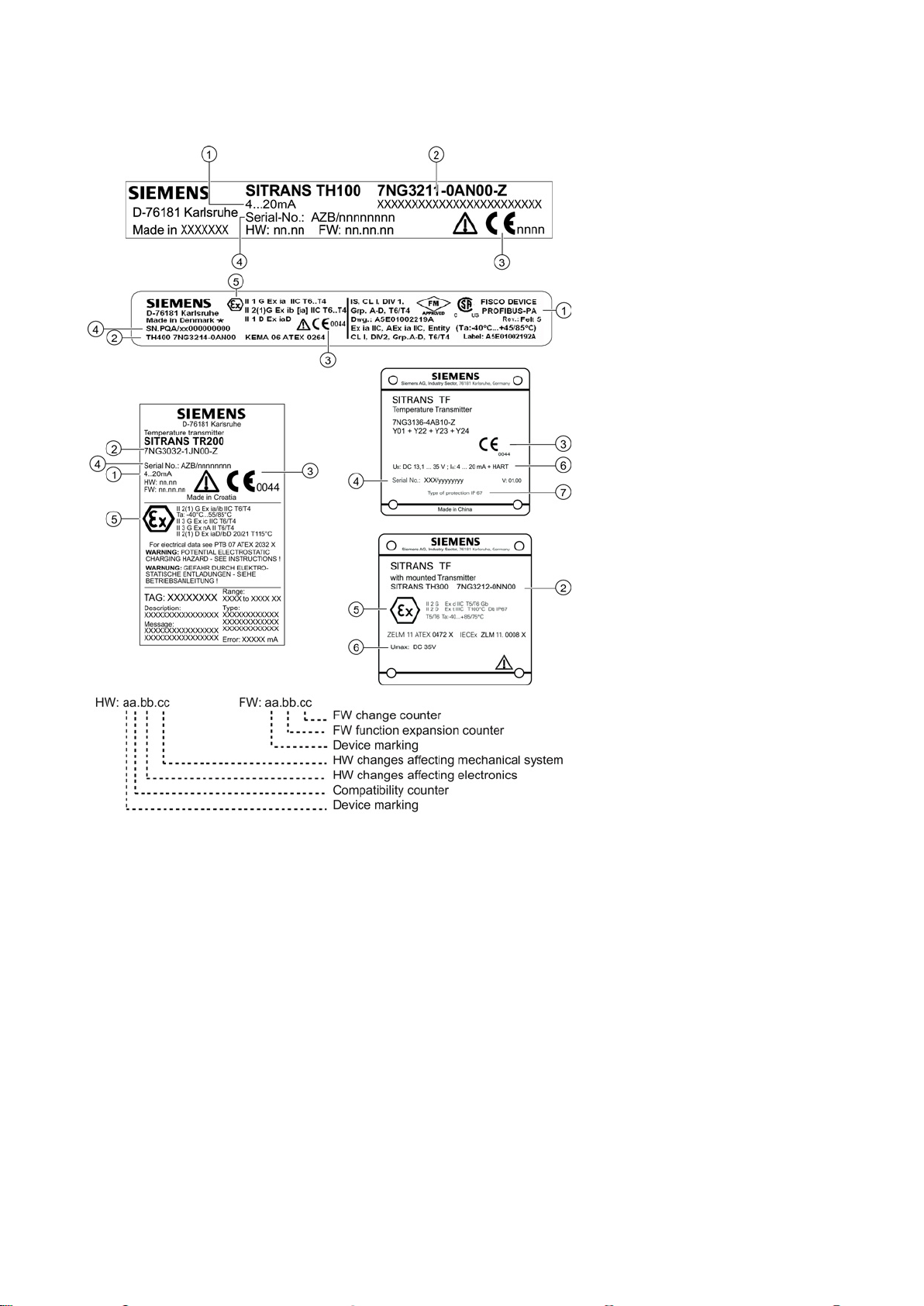
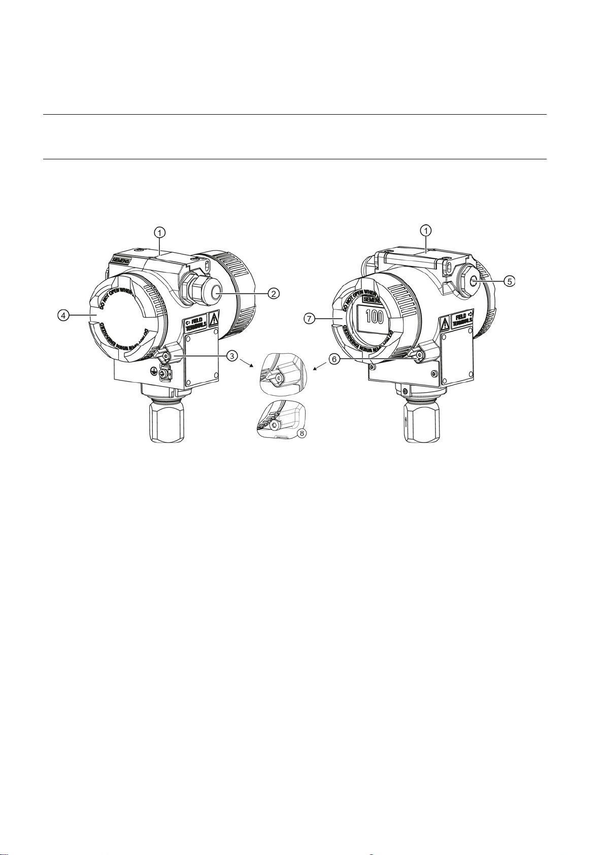
1.1
Nameplate structure
①
Version
⑤
Ex marking with Ex data
②
Order number
⑥
Electrical characteristics
③
notified body
⑦
④
Serial number
2
Safety notes
CE mark with ID number of
This device left the factory in good working condition. In order to maintain this status and to ensure safe operation of the
device, observe these instructions and all the specifications relevant to safety.
Observe the information and symbols on the device. Do not remove any information or symbols from the device. Always
keep the information and symbols in a completely legible state.
Type of IP protection
SITRANS TH/TR/TF
A5E32520700-01, 06/2013
5
Symbol
Meaning
Electromagnetic Compatibility EMC
2004/108/EC
Directive of the European Parliament and of the Council on the approximation of th
laws of the Member States relating to electromagnetic compatibility and repealing
Directive 89/336/EEC.
Atmosphère explosible ATEX
94/9/EC
Directive of the European Parliament and the Council on the approximation of the
laws of the Member States concer
for use in potentially explosive atmospheres.
WARNING
Improper device modifications
cancels the manufacturer's warranty and the product approvals.
Qualified personnel for hazardous area applications
WARNING
Unsuitable device for the hazardous area
● Only use equipment that is approved for use in the intended hazardous area and labelled accordingly.
WARNING
Loss of safety of device with type of protection "Intrinsic safety Ex i"
● Observe the specifications for the electrical data on the certificate and in Chapter "Technical data (Page 26)".
Pay attention to the operating instructions
Observe the test certification, provisions and laws applicable in your country during connection, assembly and operation.
These include, for example:
● National Electrical Code (NEC - NFPA 70) (USA)
● Canadian Electrical Code (CEC) (Canada)
Further provisions for hazardous area applications are for example:
● IEC 60079-14 (international)
● EN 60079-14 (EC)
The CE mark on the device is a sign of conformity with the following European directives:
e
ning equipment and protective systems intended
The directives applied can be found in the EC declaration of conformity for the associated device.
Danger to personnel, system and environment can result from modifications to the device, particularly in hazardous areas.
● Only carry out modifications that are described in the instructions for the device. Failure to observe this requirement
Persons who install, connect, commission, operate, and service the device in a hazardous area must have the following
specific qualifications:
● They are authorized, trained or instructed in operating and maintaining devices and systems according to the safety
regulations for electrical circuits, high pressures, aggressive, and hazardous media.
● They are authorized, trained, or instructed in carrying out work on electrical circuits for hazardous systems.
● They are trained or instructed in maintenance and use of appropriate safety equipment according to the pertinent safety
regulations.
Danger of explosion.
If the device has already been operated in non-intrinsically safe circuits or the electrical specifications have not been
observed, the safety of the device is no longer ensured for use in hazardous areas. There is a danger of explosion.
● Connect the device with type of protection "Intrinsic safety" solely to an intrinsically safe circuit.
SITRANS TH/TR/TF
6 A5E32520700-01, 06/2013
3
Mounting
WARNING
Exceeded maximum ambient or process media temperature
Refer to the information in Chapter "Technical data (Page 26)".
WARNING
Open cable inlet or incorrect cable gland
Close the cable inlets for the electrical connections. Only use cable glands or plugs which are approved for the relevant
type of protection.
WARNING
Incorrect conduit system
regulations and the requirements stated in the relevant approvals.
3.1
Mounting SITRANS TH/TR
3.1.1
Installation in the connection head
Note
The transmitter is only designed for installation in a type B co
Danger of explosion in hazardous areas.
Device damage.
● Make sure that the maximum permissible ambient and process media temperatures of the device are not exceeded.
Danger of explosion in hazardous areas.
●
Danger of explosion in hazardous areas as result of open cable inlet or incorrect conduit system.
● In the case of a conduit system, mount a spark barrier at a defined distance from the device input. Observe national
The transmitter is either secured in the base of the connection head or in the raised cover of the connection head.
Included in the transmitter's scope of delivery are:
● Springs
● Fixing screws
● Lock washers for installation on the round plate (TH200/TH300 only)
nnection head or larger.
SITRANS TH/TR/TF
A5E32520700-01, 06/2013
7
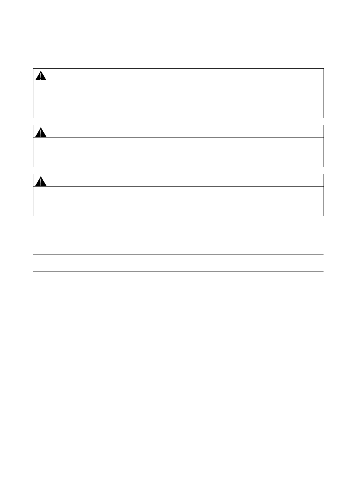
Securing the transmitter
in the connection head cover
in the connection head base
①
Transmitter
②
Ceramic base of the measuring element
③
Connection head
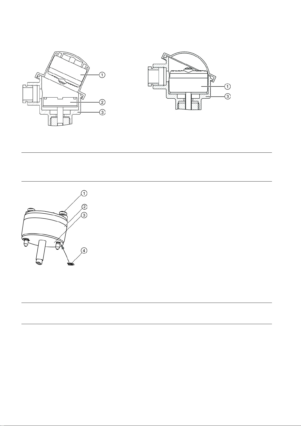
Note
Using the lock washers (TH200/TH300 only)
The lock washers
is directly installed on the round plate
①
Fixing screw M4x35
②
Transmitter
③
Round plate
④
Lock washer DIN 6799 - 3.2 A2
3.1.2
SITRANS TH installation on DIN rail and G rail
Note
Fixing rings
The fixing rings included in the scope of delivery for the transmitter are not required for the installation on DIN rails or
④ included in the delivery are only required for securely fastening the transmitter when the transmitter ②
:
③ for a temperature probe.
You can either install the transmitter on a 35 mm DIN rail or on a 32 mm G rail. DIN EN 60715 applies to DIN rails and G
rails in this context. The DIN rail adapter required for installation can be ordered as an accessory under the Order No.
7NG3092-8KA.
Adhere to the ambient conditions specified in the technical data.
SITRANS TH/TR/TF
8 A5E32520700-01, 06/2013
G rails.
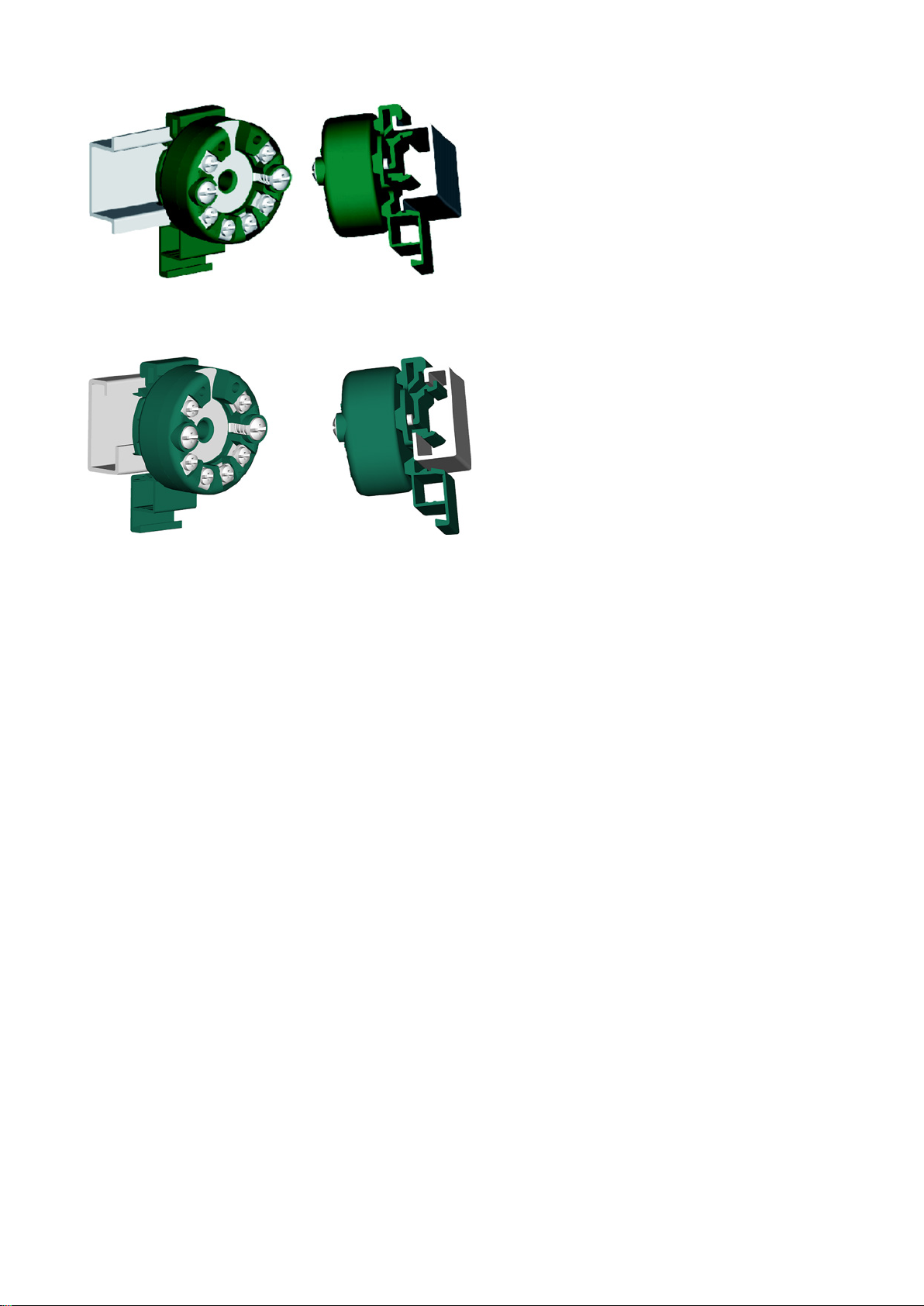
3.1.3
SITRANS TR installation on a DIN rail
Figure 3-1 Securing the transmitter on DIN rails
Figure 3-2 Securing the transmitter on G rails
The transmitter is secured to a 35 mm DIN rail to DIN EN 60715.
Comply with the ambient conditions specified in the technical data.
SITRANS TH/TR/TF
A5E32520700-01, 06/2013
9
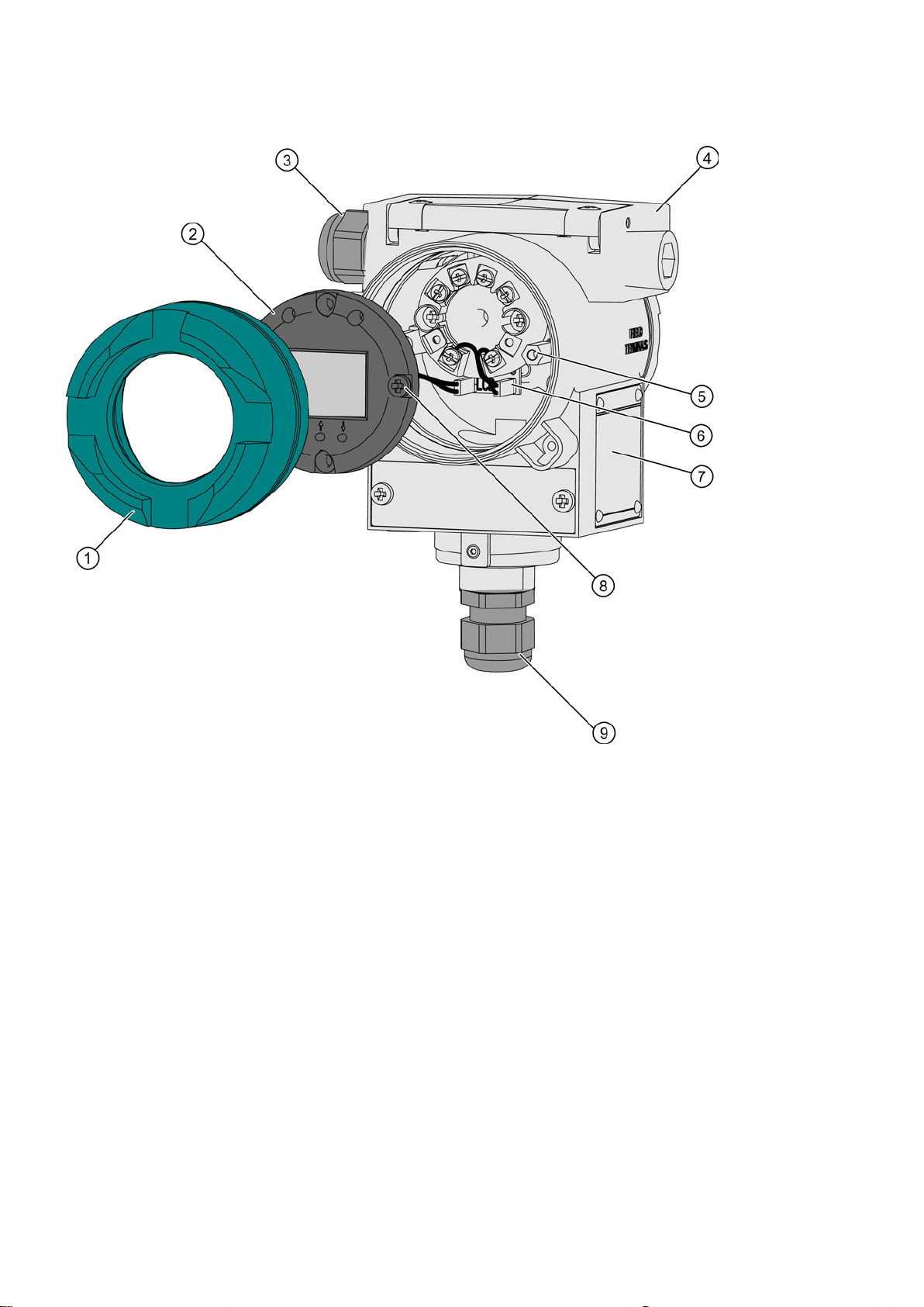
3.2
Mounting SITRANS TF
①
Cover with inspection window
⑥
Plug-in connector from SITRANS TH200 or TH300
②
Display module (digital display)
⑦
Ex nameplate
③
supply/analog output
⑧
④
SITRANS TF field housing
⑨
Cable gland for sensor cable
⑤
Spacers
Procedure
Cable gland for auxiliary power
Figure 3-3 Design of SITRANS TF with display module (digital display)
1. Unscrew the front cover ①.
2. Screw the two spacers
3. Remove the left-hand shorting bars on the PC board located under the transmitter.
4. Insert the plug-in connector from the display module. The plus side with the red wire must face upward.
SITRANS TH/TR/TF
10 A5E32520700-01, 06/2013
⑤ into the right and left threads. Torque approx. 3 Nm.
M4 screw
Note
Reverse polarity protection
The display module has integrated reverse polarity protection. The display module will not function if the polarity is
reversed, but will not be damaged. Make sure the polarity is correct. If the display module does not function, reverse the
polarity of the plug
4
Connection
WARNING
Unsuitable cables and/or cable glands
● After installation check that the cables are seated firmly.
WARNING
Dangerous contact voltage
installations with rated voltages below 1000 V.
NOTICE
Ambient temperature too high
°C (68 °F) higher.
WARNING
Improper power supply
be found in the certificates, in Chapter "Technical data (Page 26)" or on the nameplate.
-in connector.
5. Using the two M4 screws ⑧ supplied, attach the display module to the two spacers ⑤ in the electronics compartment of
the SITRANS TF field housing.
Torque approx. 2.5 Nm.
6. Use the three buttons to assign parameters to the display module
②.
7. Screw the cover back into place. We recommend using a cover with an inspection window, e.g. 7MF4997-1BE.
8. To remove the display module, follow the reverse procedure.
Danger of explosion in hazardous areas.
● Only use suitable cables and cable glands complying with the requirements specified in Chapter "Technical data
(Page 26)".
● Tighten the cable glands in accordance with the torques specified in Chapter "Technical data (Page 26)".
● When replacing cable glands use only cable glands of the same type.
Danger of electric shock in case of incorrect connection.
● For the electrical connection specifications, refer to the information in Chapter "Technical data (Page 26)".
● At the mounting location of the device observe the applicable directives and laws for installation of electrical power
Damage to cable sheath.
● At an ambient temperature ≥ 60 °C (140 °F), use heat-resistant cables suitable for an ambient temperature at least 20
Danger of explosion in hazardous areas as result of incorrect power supply, e.g. using direct current instead of alternating
current.
● Connect the device in accordance with the specified power supply and signal circuits. The relevant specifications can
SITRANS TH/TR/TF
A5E32520700-01, 06/2013
11
WARNING
Improper laying of shielded cables
● If grounding is required at both ends, use an equipotential bonding conductor.
WARNING
Connecting device in energized state
Exceptions
● Exceptions for type of protection "Non-sparking nA" (Zone 2) are regulated in the relevant certificate
WARNING
Incorrect selection of type of protection
unrecognizable on the nameplate.
Note
Improvement of interference immunity
●
●
●
●
● Refer to HART communication information in Chapter "Technical data (Page 26)".
Note
Limited range of use
If the device has been operated outside the ambient conditions specified for potentially explosive atmospheres, you may no
longer operate the device in potentially explosive atmospheres. Make sure to permanently m
nameplate.
WARNING
Risk of explosion when using unsuitable HART device
Note
Electrical data and T
amb
Electrical data and T
(
Danger of explosion through compensating currents between hazardous area and the non-hazardous area.
● Only ground shielded cables that run into the hazardous area at one end.
Danger of explosion in hazardous areas.
● Connect devices in hazardous areas only in a de-energized state.
:
● Circuits of limited energy may also be connected in the energized state in hazardous areas.
Danger of explosion in areas subject to explosion hazard.
This device is approved for several types of protection.
1. Decide in favor of one type of protection.
2. Connect the device in accordance with the selected type of protection.
3. In order to avoid incorrect use at a later point, make the types of protection that are not used permanently
Lay signal cables separate from cables with voltages > 60 V.
Use cables with twisted wires.
Keep device and cables in distance to strong electromagnetic fields.
Use shielded cables to guarantee the full specification according to HART.
ask all Ex markings on the
Only intrinsically safe HART modems or HART communicators are allowed to be operated in the intrinsically safe area or
on intrinsically safe circuits.
are dependent on Ex-protection class, see Certificates
amb
http://www.siemens.com/processinstrumentation/certificates)
SITRANS TH/TR/TF
12 A5E32520700-01, 06/2013

4.1
Safety notes for connecting in hazardous areas TH100
Zone 0, 1, 2 in type of protection "ia/ib/ic" - intrinsic safety
Maximum values of the auxiliary power supply and signal circuits:
Ui = 30 V DC
Ii = 100 mA
Pi = 750 mW
Li = 106 μH
Ci = 7.3 nF
Maximum values of the sensor circuit for Ex ia:
U0= 9.6 V DC:
I0 = 7.6 mA
P0 = 12.5 mW
L0 [mH]
50
10 2 0,5
C0 [nF]
560
700
940
1250
Zone 2 in type of protection "ic"
Maximum values of the auxiliary power supply and signal circuits:
Ui = 32 V DC
Ii = 100 mA
Pi = 750 mW
Li = 106 μH
Ci = 7.3 nF
Maximum values of the sensor circuit
U0= 9.6 V DC:
I0 = 7.6 mA
P0 = 12.5 mW
L0 [mH]
50
10 2 0,5
C0 [nF]
560
700
940
1250
Zone 2 in type of protection "nA" - non-sparking resources
Maximum values of the sensor circuit
U0= 9.6 V DC:
I0 = 7.6 mA
P0 = 12.5 mW
L0 [mH]
50
10 2 0,5
C0 [nF]
560
700
940
1250
Additional requirements for use in dust explosion protected areas
● Only connect the transmitter, in accordance with the certificate of compliance, to devices certified as intrinsically-safe.
● If the connection head is made of aluminum, the requirements of EN 60079-26, section 4.3.3, must be observed for uses
where the device category 1 G is required.
● The transmitter must be mounted in an enclosure in order to provide a degree of protection of at least IP20 according to
EN60529
● If the connection head is made of aluminum, the requirements of EN 60079-26, section 4.3.3, must be observed for uses
where the device category 1 G is required.
● Only connect the transmitter to devices that have at least been approved as "ic" certified devices (intrinsically safe) of
Category 3.
● Be sure to observe the respective values.
● The transmitter must be mounted in an enclosure in order to provide a degree of protection of at least IP20 according to
EN60529
● Install the transmitter in an enclosure meeting the degree of protection IP54 per EN 60529, e.g. in a type B connection
head per DIN 43729.
● Adhere to the conditions for installers applicable to this type of protection.
● The maximum approved input voltage is U
● Take measures to ensure that the supply voltage (including transients) does not rise above 140 % of the rated voltage.
= 35 V DC.
n
Install the transmitter in an enclosure suitable for the respective type of dust and corresponding Zone in accordance with the
inspection certificate valid in your country.
SITRANS TH/TR/TF
A5E32520700-01, 06/2013
13

4.2
Safety notes for connecting in hazardous TH200/300
Zone 0, 1, 2 in type of protection "ia/ib/ic" - intrinsic safety
Maximum values of the auxiliary power supply and signal circuits:
Ui = 30 V DC
Ii = 100 mA
Pi = 750 mW
Li = 104 μH
Ci = 11 nF
Maximum values of the sensor circuit for Ex ia:
U0= 6 V DC:
I0 = 25 mA
P0 = 37 mW
L0 [mH]
50
10 1 0.1
C0 [μF]
1
1.6
2.6
4.8
Zone 2 in type of protection "nA" - non-sparking resources
Maximum values of the sensor circuit:
U0= 6 V DC:
I0 = 25 mA
P0 = 37 mW
L0 [mH]
50
10 1 0.1
C0 [μF]
1
1.6
2.6
4.8
Additional requirements for use in dust explosion protected areas
4.3
Safety notes for connecting in hazardous TR200/300
Zone 0, 1, 2 in type of protection "ia/ib/ic" - intrinsic safety
Maximum values of the auxiliary power supply and signal circuits:
Ui = 30 V DC
Ii = 100 mA
Pi = 750 mW
Li = 2 μH
Ci = 13 nF
The 4 to 20 mA input and sensor circuits are electrically isolated and have been tested with a voltage of 1.5 kV DC/1 minute.
The sensor circuit is reliably galvanically isolated from the auxiliary power supply and signal circuit, up to a peak value of the
rated voltage of 60 V. Be sure to observe the construction directives valid at the construction location for electrical resources
in hazardous areas. In Europe, this is the standard EN 60079-14.
● Only connect the transmitter, in accordance with the certificate of compliance, to devices certified as intrinsically-safe.
● If the connection head is made of aluminum, the requirements of EN 60079-26, section 4.3.3, must be observed for uses
where the device category 1 G is required.
● The transmitter must be mounted in an enclosure in order to provide a degree of protection of at least IP20 according to
EN60529
● Install the transmitter in an enclosure meeting the degree of protection IP54 per EN 60529, e.g. in a type B connection
head per DIN 43729.
● Adhere to the conditions for installers applicable to this type of protection.
● The maximum approved input voltage is U
● Take measures to ensure that the supply voltage (including transients) does not rise above 140 % of the rated voltage.
Install the transmitter in an enclosure suitable for the respective type of dust and corresponding Zone in accordance with the
inspection certificate valid in your country.
The 4 to 20 mA input and sensor circuits are electrically isolated and have been tested with a voltage of 1.5 kV DC/1 minute.
The sensor circuit is reliably galvanically isolated from the auxiliary power supply and signal circuit, up to a peak value of the
rated voltage of 60 V. Be sure to observe the construction directives valid at the construction location for electrical resources
in hazardous areas. In Europe, this is the standard EN 60079-14.
● Only connect the transmitter, in accordance with the certificate of compliance, to devices certified as intrinsically-safe.
= 32 V DC.
n
SITRANS TH/TR/TF
14 A5E32520700-01, 06/2013

Maximum values of the sensor circuit for Ex ia:
U0= 6 V DC:
I0 = 25 mA
P0 = 37 mW
L0 [mH]
50
10 1 0.1
Zone 2 in type of protection "ic" - intrinsic safety
Maximum values of the auxiliary power supply and signal circuits:
Ui = 30 V DC
Ii = 100 mA
Pi = 750 mW
Li = 2 μH
Ci = 13 nF
Maximum values of the sensor circuit:
U0= 6 V DC:
I0 = 25 mA
P0 = 37 mW
L0 [mH]
50
10 1 0.1
C0 [μF]
1
1.6
2.6
4.8
Zone 2 in type of protection "nA" - non-sparking resources
Additional requirements for use in dust explosion protected areas
4.4
Safety notes for connecting in hazardous TH400
Zone 0 in type of protection "ia" - intrinsic safety
Maximum values of the auxiliary power supply and signal circuits:
Li = 1 μH
Ci = 2 nF
Maximum values of the auxiliary power supply and signal circuits:
Ui = 30 V DC
Ii = 300 mA
Pi = 1300 mW
Li = 1 μH
Ci = 2 nF
C0 [μF] 1 1.6 2.6 4.8
● Only connect the transmitter, in accordance with the certificate of compliance, to devices certified as intrinsically-safe.
● Adhere to the conditions for installers applicable to this type of protection.
● The maximum approved input voltage is Un = 32 V DC.
● Take measures to ensure that the supply voltage (including transients) does not rise above 140 % of the rated voltage.
Install the transmitter in an enclosure suitable for the respective type of dust and corresponding Zone in accordance with the
inspection certificate valid in your country.
The input circuit is thus electrically isolated from the sensor circuit. The isolation does not satisfy the requirements for
infallible electrical isolation in the sense of the intrinsic safety standard EN / IEC 60079-11, but does withstand a test voltage
of 500 V AC/1 minute.
● Only connect the transmitter, in accordance with the certificate of compliance, to devices certified as intrinsically-safe.
● If the connection head is made of aluminum, the requirements of EN 60079-26, section 4.3.3, must be observed for uses
where the device category 1 G is required.
● The transmitter must be mounted in an enclosure in order to provide a degree of protection of at least IP20 according to
EN60529
Table 4-1 For T
Ui = 30 V DC Ii = 120 mA Pi = 840 mW
≤ 85 °C (T4); Ta ≤ 70 °C (T5); Ta ≤ 60 °C (T6)
a
Table 4-2 For Ta ≤ 75 °C (T4); Ta ≤ 65 °C (T5); Ta ≤ 45 °C (T6)
SITRANS TH/TR/TF
A5E32520700-01, 06/2013
15

Maximum values of the auxiliary power supply and signal circuits in accordance with FISCO:
Ui = 17.5 V DC
Ii = 250 mA
Pi = 2000 mW
Li = 1 μH
Ci = 2 nF
Maximum values of the auxiliary power supply and signal circuits in accordance with FISCO:
Ui = 15 V DC
Ii = any
Pi = any
Li = 1 μH
Ci = 2 nF
Maximum values of the sensor circuit for Ex ia:
U0= 5.7 V DC:
I0 = 8.4 mA
P0 = 12 mW
L0 [mH]
200
C0 [μF]
40
Zone 1 in type of protection "ib" - intrinsic safety
Maximum values of the auxiliary power supply and signal circuits:
Ui = 30 V DC
Ii = 250 mA
Pi = 5320 mW
Li = 1 μH
Ci = 2 nF
Maximum values of the auxiliary power supply and signal circuits in accordance with FISCO:
Ui = 17.5 V DC
Ii = any
Pi = any
Li = 1 μH
Ci = 2 nF
Maximum values of the sensor circuit for Ex ia:
U0= 5.7 V DC:
I0 = 8.4 mA
P0 = 12 mW
L0 [mH]
200
C0 [μF]
40
Zone 2 in type of protection "nL/ic"
Maximum values of the auxiliary power supply and signal circuits:
Ui = 32 V DC
Ii = any
Pi = any
Li = 1 μH
Ci = 2 nF
Table 4-3 For Ta ≤ 85 °C (T4); Ta ≤ 60 °C (T5); Ta ≤ 45 °C (T6)
Table 4-4 For Ta ≤ 85 °C (T4); Ta ≤ 60 °C (T5); Ta ≤ 45 °C (T6)
● Only connect the transmitter, in accordance with the certificate of compliance, to devices certified as intrinsically-safe.
● The transmitter must be mounted in an enclosure in order to provide a degree of protection of at least IP20 according to
EN60529
Table 4-5 For T
≤ 85 °C (T4); Ta ≤ 75 °C (T5); Ta ≤ 60 °C (T6)
a
Table 4-6 For Ta ≤ 85 °C (T4); Ta ≤ 75 °C (T5); Ta ≤ 60 °C (T6)
● Install the transmitter in an enclosure meeting the degree of protection IP54 per EN 60529, e.g. in a type B connection
head per DIN 43729.
● Only connect the transmitter to devices that have at least been approved as certified devices of Category 3.
● Be sure to observe the respective values.
Table 4-7 For T
SITRANS TH/TR/TF
≤ 85 °C (T4); Ta ≤ 75 °C (T5); Ta ≤ 60 °C (T6)
a
16 A5E32520700-01, 06/2013
Maximum values of the auxiliary power supply and signal circuits in accordance with FNICO/FISCO:
Ui = 17.5 V DC
Ii = any
Pi = any
Li = 1 μH
Ci = 2 nF
Maximum values of the sensor circuit:
U0= 5.7 V DC:
I0 = 8.4 mA
P0 = 12 mW
L0 [mH]
200
C0 [μF]
40
Zone 2 in type of protection "nA" - non-sparking resources
Maximum values of the sensor circuit:
U0= 5.7 V DC:
I0 = 8.4 mA
P0 = 12 mW
L0 [mH]
200
C0 [μF]
40
Additional requirements for use in dust explosion protected areas
4.5
Safety notes for connecting in hazardous TF
WARNING
Risk of explosion due to electrostatic charge
Type of protection "Flameproof enclosure" and "Dust protection by enclosure"
For SITRANS TF connection in hazardous areas
4.6
Special safety consideration for connecting SITRANS TH300/TH400
4.7
Test terminals for output signal
Table 4-8 For Ta ≤ 85 °C (T4); Ta ≤ 75 °C (T5); Ta ≤ 60 °C (T6)
● Install the transmitter in an enclosure meeting the degree of protection IP54 per EN 60529, e.g. in a type B connection
head per DIN 43729.
● Adhere to the conditions for installers applicable to this type of protection.
● The maximum approved input voltage is Un = 32 V DC.
Install the transmitter in an enclosure suitable for the respective type of dust and corresponding Zone in accordance with the
inspection certificate valid in your country. The surface temperature of the enclosure is euqal to T
with a maximum thickness of 5 mm.
To prevent an electrostatic charge in a hazardous area, close the key cover during operation and tighten the screws
securely.
Only open devices with type of protection "Flameproof enclosure" in hazardous areas when the power to the device is
turned off, otherwise there is a risk of explosion.
The SITRANS TF comes with a built-in transmitter: SITRANS TH200, TH300, or TH400. See Safety notes for connecting in
hazardous TH200/300 (Page 14).
● Use shielded cables to ensure the full specification according to HART, PROFIBUS PA, or FOUNDATION Fieldbus
plus 20 K for a dust layer
a
The "Test +" and "Test -" test terminals are used for checking the 4 to 20 mA current with an amperemeter. The voltage drop
across the amperemeter must not exceed 0.4 V for a 23 mA output current.
SITRANS TH/TR/TF
A5E32520700-01, 06/2013
17
4.8
SITRANS TH/TR connection
4.8.1
Connecting the auxiliary power supply
Procedure
4.8.2
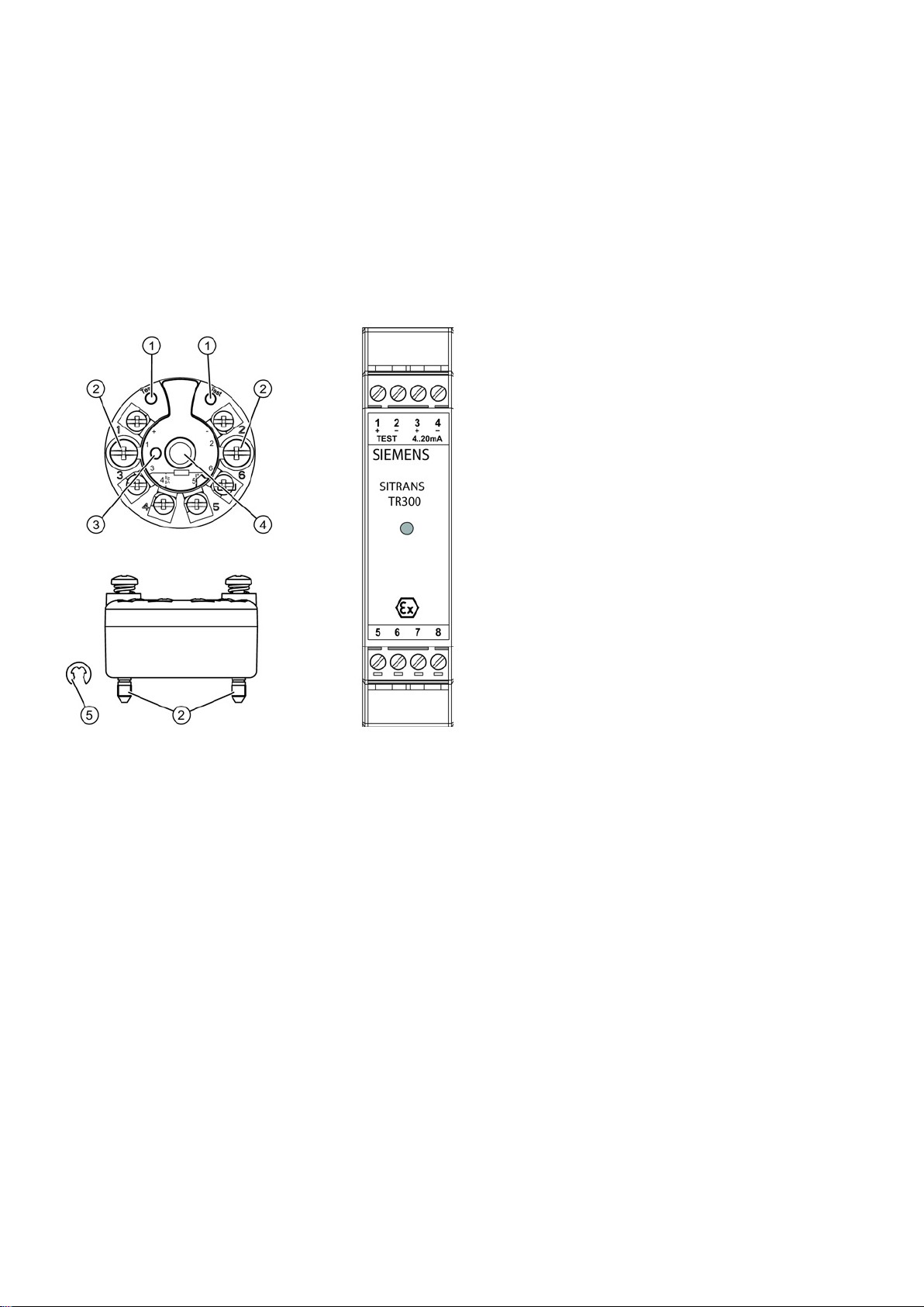
Connection assignment
①
Test terminal
②
Fixing screw M4
③
LED (SITRANS TH200/TH300 only)
④
Internal diameter of center hole 6,3 mm (0.25")
⑤
Lock washer DIN 6799 - 3.2 A2 (SITRANS TH200/TH300 only)
connections:
3, 4, 5, and 6
Sensor connections (for TH100 Pt100 only)
connections:
amperemeter
3 (+) and 4 (-)
Auxiliary power supply U
aux
, output current I
out
5, 6, 7 and 8
Connection of sensors, see terminal diagrams SITRANS TR200/TR300
Connect the wires for the auxiliary power supply to terminals "1"(+) and "2"(-). Ensure that the polarity is correct. The device
is reverse polarity protected.
SITRANS TH
SITRANS TR
Figure 4-1 Connection assignment SITRANS TH
1 (+) and 2 (-) Auxiliary power supply U
1 (+) and 2 (-) Test terminals (test) for measuring the output current using an
, output current I
aux
out
SITRANS TH/TR/TF
18 A5E32520700-01, 06/2013
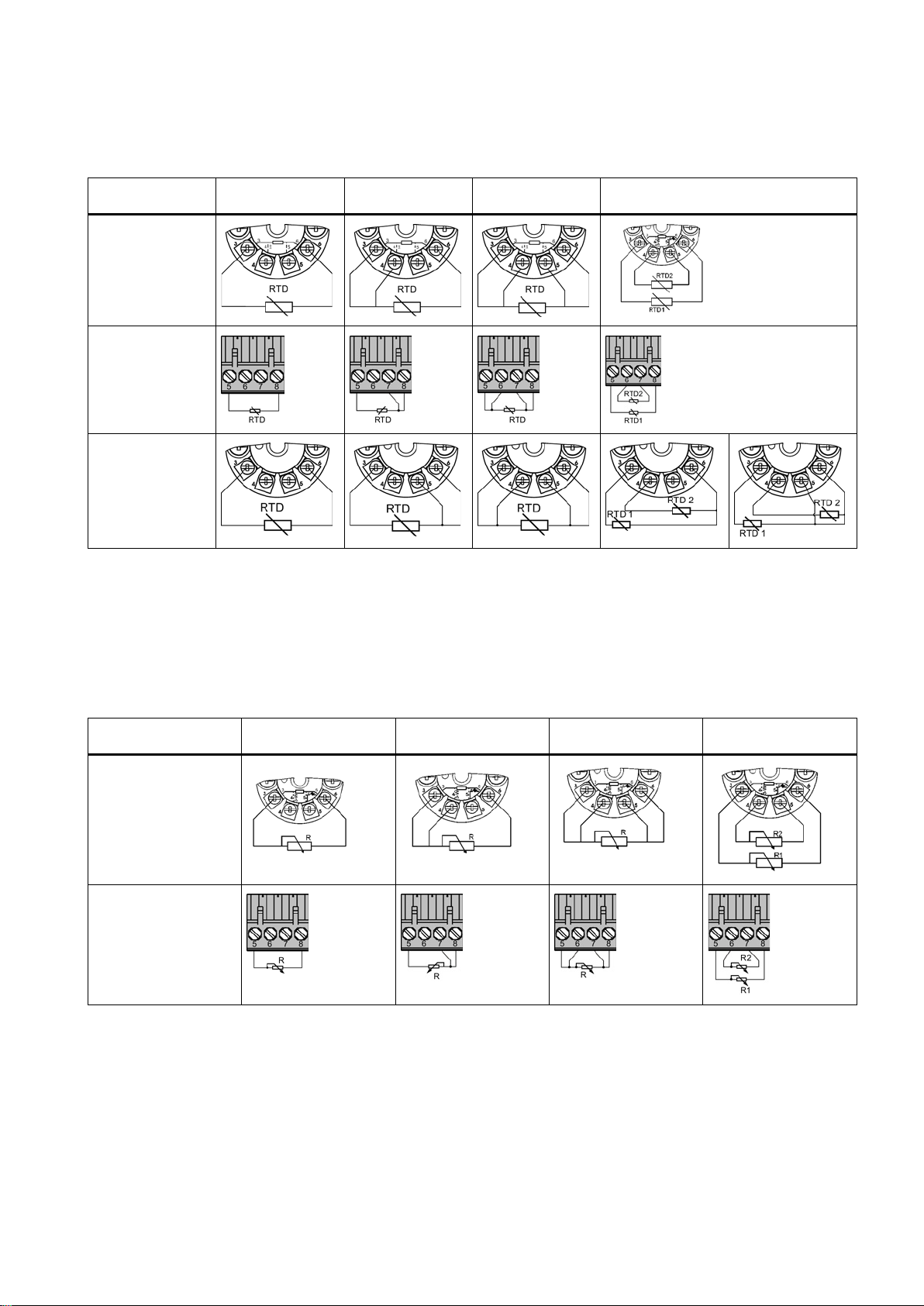
4.8.3
Resistance thermometer connections
Two-wire1)
Three-wire
Four-wire
Averaging/determination of difference2), not
for TH100
TH100,
TH200/TH300
(for TH100 Pt100
only)
TR200/TR300
TH400
1)
2)
electrically insulated using tape.
4.8.4
Resistor connections
Two-wire1)
Three-wire
Four-wire
Averaging/determination
of difference
1) 2)
TH200/TH300
TR200/TR300
Table 4-9 Resistance input options:
Line resistance for correction is programmable
Terminal No. 5 has no function in the version with three-wire input, and must not be connected. When using RTDs in a
version with four-wire input but when selecting a three-wire input, the cores of the unused fourth sensor line must be
Table 4-10 Resistor input options:
SITRANS TH/TR/TF
A5E32520700-01, 06/2013
19
Two-wire1)
Three-wire
Four-wire
Averaging/determination
of difference
1) 2)
TH400
1)
2)
three-wire input
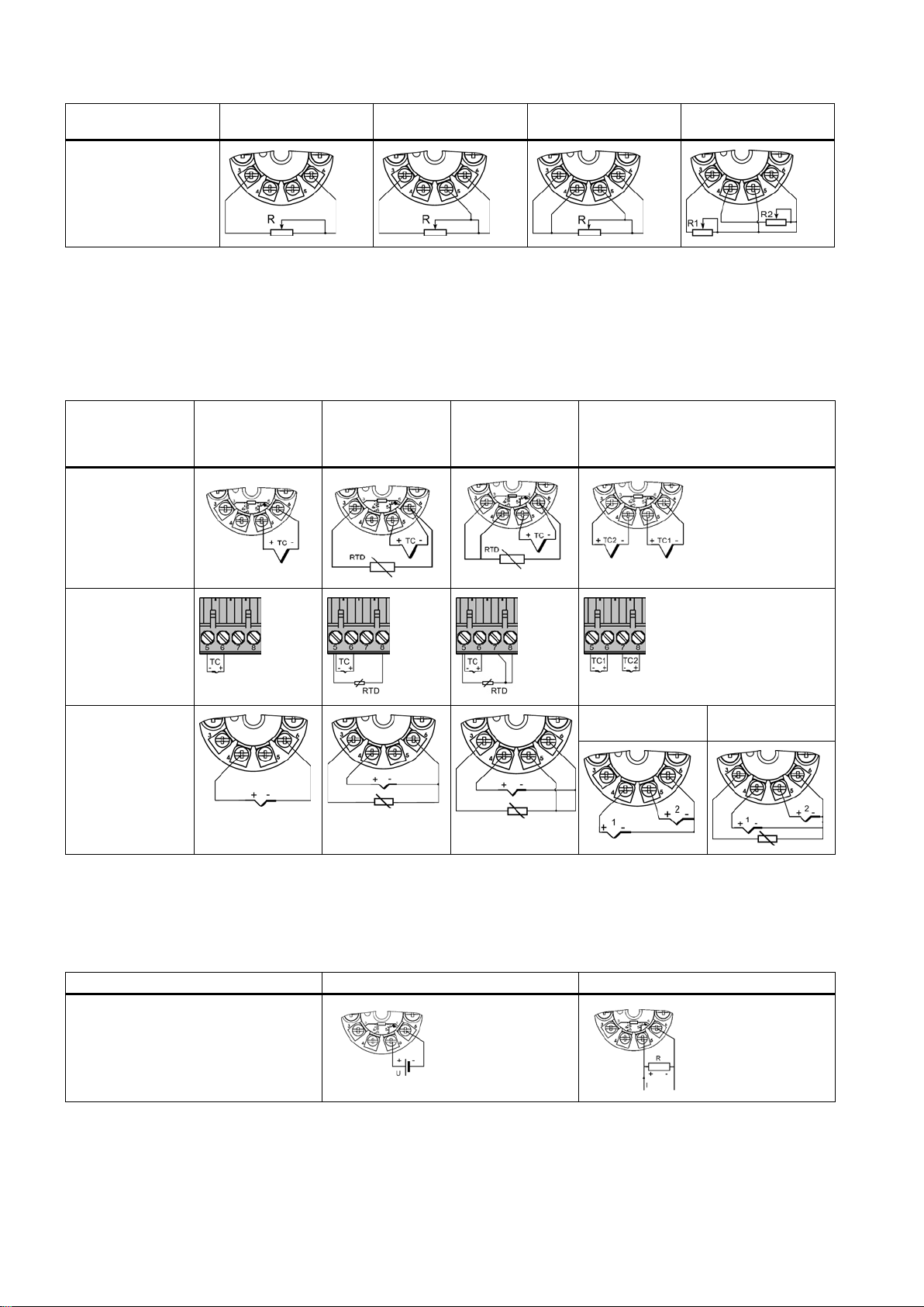
4.8.5
Thermocouple connections
Cold junction
compensation/fixed
value
Cold junction
compensation with
external Pt100 in
two-wire input1)
Cold junction
compensation with
external Pt100 in
three-wire input1)
Averaging/determination of difference with
internal cold junction compensation
TH200/TH300
TR200/TR300
TH400
with external cold
junction
1)
Line resistance for correction is programmable
4.8.6
Voltage and current connection
Voltage
Current
TH200/TH300
Line resistance for correction is programmable
For TH400: Determination of mean value, difference, or redundancy resistance in two-wire input, or 1 resistance in
Table 4-11 Thermocouple input options:
Table 4-12 Voltage and current connections:
SITRANS TH/TR/TF
20 A5E32520700-01, 06/2013

Voltage
Current
TR200/TR300
TH400
and redundancy using 2 power supplies
1 power supply TH400 measuring mean value, difference,
SITRANS TH/TR/TF
A5E32520700-01, 06/2013
21
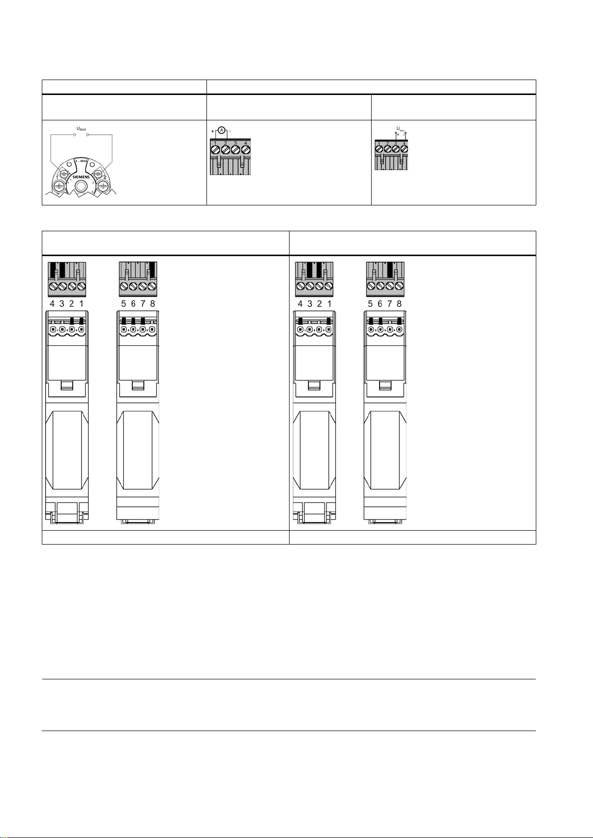
4.8.7
Power supply connection
SITRANS TH
SITRANS TR
for each product
20 mA (U
)
4.8.8
Coding profiles
Coding profile for SITRANS TR200/TR300
with protection against explosions (intrinsically safe)
Coding profile for SITRANS TR200/TR300
without protection against explosions
MLFB: 7NG303*-1JN00
MLFB: 7NG303*-0JN00
4.9
SITRANS TF onnection
4.9.1
Opening the device
Procedure
4.9.2
SITRANS TF Connection
Note
SITRANS TF Connection
The SITRANS TF comes with a built
SITRANS TF, use the appropriate sensor/transmitter connetion diagram, see
TH100 displayed here, display differs
Test terminals (Test) Auxiliary power supply connection/4 to
aux
1. Unscrew the cover of the electrical cable compartment. See Chapter "Closing the device (Page 24)".
SITRANS TH/TR/TF
22 A5E32520700-01, 06/2013
An identification text "FIELD TERMINAL" is provided at the side of the housing.
-in transmitter: SITRANS TH200, TH300, or TH400. To connect a sensor to the
SITRANS TH/TR connection (Page 18).
See also
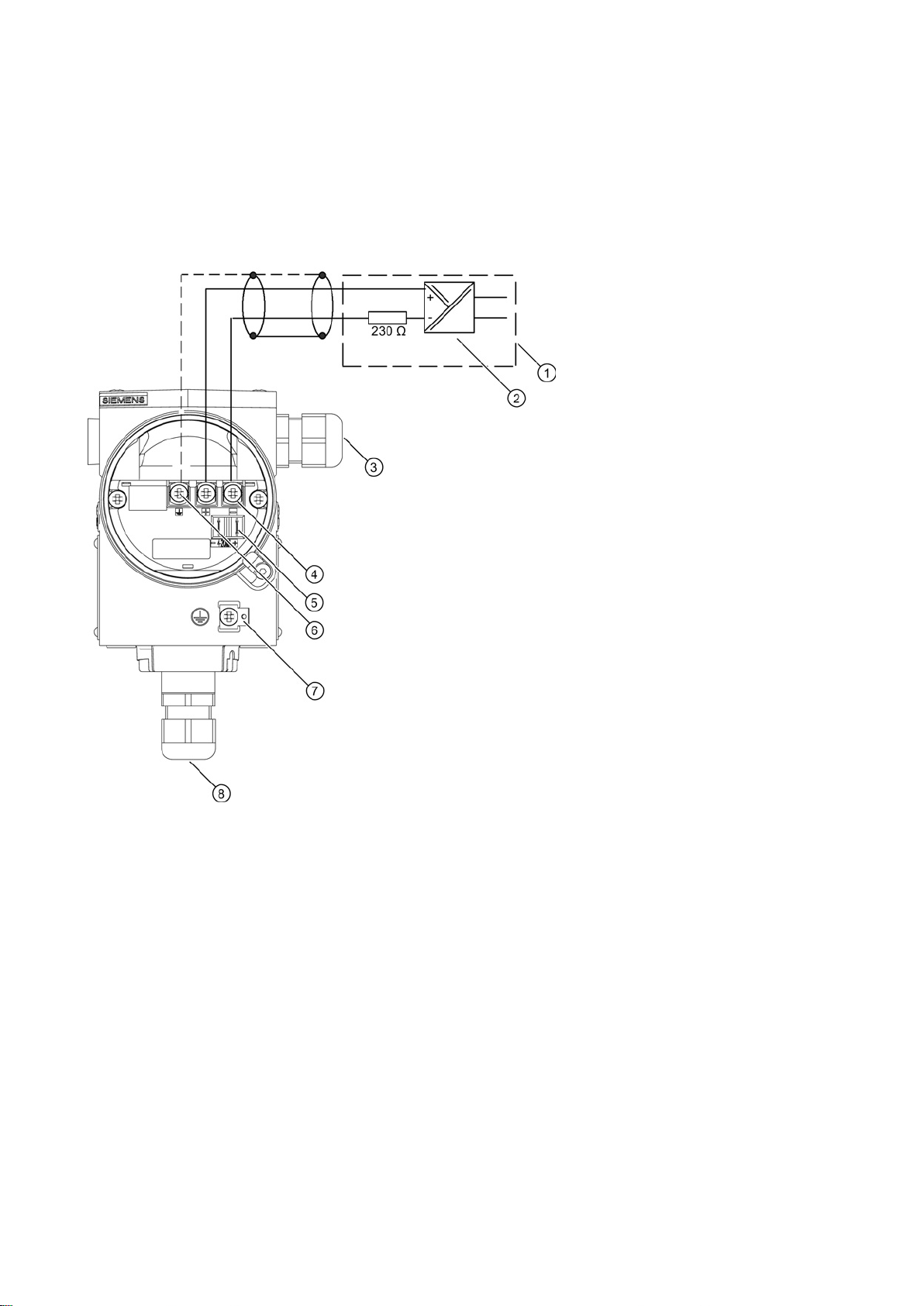
4.9.3
Auxiliary power supply electrical connection
Overview
①
⑤
or connection for external display
②
SITRANS TH300
⑥
③
output
⑦
④
Connecting terminals "+" and "-"
⑧
Cable gland for sensor signal
Procedure
Nameplate structure (Page 5)
Auxiliary power supply
Example feed splitter for SITRANS TF with built-in
Cable gland for auxiliary power supply/analog
Figure 4-2 Auxiliary power supply electrical connection
1. Connect the wires for the auxiliary power supply ① to terminals "1"(+) and "2"(-) ④. Ensure that the polarity is correct.
The device is reverse polarity protected.
2. Connect the cable shield.
Connect the shield of the signal cables to the shield support
housing.
SITRANS TH/TR/TF
A5E32520700-01, 06/2013
Test connector for direct current measuring device
Shield support
Protective conductor connector
⑥. The shield support is electrically connected with the
23
4.9.4
Closing the device
Procedure
Note
Key cover
Key cover
①
Key cover
⑤
Blanking plug
②
Cable bushing
⑥
Safety catch (front)
③
Safety catch (back)
⑦
Cover (front), optionally with inspection window
④
Cover (rear) for electrical terminal compartment
⑧
Safety catch for stainless steel enclosure
5
Commissioning
5.1
Commissioning
Procedure
① without function. Key cover is sealed in the factory.
1. Screw the covers ④⑦ on as far as they will go.
2. Secure the covers with the cover catch
3. Check the tightness of the blanking plugs
③⑥.
⑤ and cable gland ② in accordance with the degree of protection.
Figure 4-3 Device view - left: rear view, right: front view
1. Program the transmitter's operating data according to the actual requirements.
If applicable, enter the changed operating data on the additional plate on the enclosure.
2. Assemble the transmitter.
3. Connect the sensor to the power supply, see Chapter "Power supply connection (Page 22)".
4. Turn on the auxiliary power supply.
5. Wait about 10 seconds. After this start-up time the transmitter is operational.
SITRANS TH/TR/TF
24 A5E32520700-01, 06/2013
Note
Warming-up
To obtain exact measured values, the transmitter needs to be allowed to warm up for five minutes or so after the power
supply has been switched on.
6
Service and maintenance
6.1
Maintenance
WARNING
Impermissible repair and maintenance of the device
● Repair and maintenance must be carried out by Siemens authorized personnel only.
WARNING
Impermissible repair of explosion protected devices
● Repair must be carried out by Siemens authorized personnel only.
Cleaning the enclosure
WARNING
Electrostatic charge
● Prevent electrostatic charging in hazardous areas.
The device is maintenance-free. However, a periodic inspection according to pertinent directives and regulations must be
carried out.
An inspection can include check of:
● Ambient conditions
● Seal integrity of the process connections, cable entries, and cover screws
● Reliability of power supply, lightning protection, and grounds
Danger of explosion in areas subject to explosion hazard.
● Clean the outside of the enclosure and the display window using a cloth moistened with water or a mild detergent.
● Do not use aggressive cleaning agents or solvents. Plastic components or painted surfaces could be damaged.
Danger of explosion in hazardous areas if electrostatic charges develop, for example, when cleaning plastic enclosures
with a dry cloth.
SITRANS TH/TR/TF
A5E32520700-01, 06/2013
25

7
Technical data
Note
SITRANS TF
For SITRANS TF, please refer to the built
Input
SITRANS TH100
SITRANS TH200/TH300,
TR200/TR300
SITRANS TH400
Interface1)
● Standard connection
x x x
● Averaging
x x
x x
Sensor current
approx. 0,4 mA
≤ 0,45 mA
nominal 0,2 mA
break monitoring
Break monitoring
x x
Short circuit monitoring
x x
Resistance thermometers
SITRANS TH100/200/300,
TR200/TR300
(for TH100, only PT100), min. span
10 °C (18 °F)
SITRANS TH400
Range °C (°F)
Range °C (°F)
Input point
According to IEC 60751
● Pt25
-200 ... +850 (-328 ... +1562)
-200 ... +850 (-328 ... +1562)
-200 ... +850 (-328 ... +1562)
-200 ... +850 (-328 ... +1562)
● Pt100 ... Pt200
-200 ... +850 (-328 ... +1562)
-200 ... +850 (-328 ... +1562)
-200 ... +850 (-328 ... +1562)
-200 ... +850 (-328 ... +1562)
● Pt1000
-200 ... +350 (-328 ... +662)
-200 ... +850 (-328 ... +1562)
● Ni25 ... Ni1000
-60 ... +250 (-76 ... +482)
-60 ... +250 (-76 ... +482)
According to JIS C1604-81
● Pt25
-200 ... +649 (-328 ... +1200)
-200 ... +850 (-328 ... +1562)
● Pt50
-200 ... +649 (-328 ... +1200)
-200 ... +850 (-328 ... +1562)
● Pt100 ... Pt200
-200 ... +649 (-328 ... +1200)
-200 ... +850 (-328 ... +1562)
● Pt500
-200 ... +649 (-328 ... +1200)
-200 ... +850 (-328 ... +1562)
● Pt1000
-200 ... +350 (-328 ... +662)
-200 ... +850 (-328 ... +1562)
● Cu10 … Cu1000
-50 ... +200 (-58 ... +392)
● Differentiation
-in transmitter's specifications (SITRANS TH200, TH300, TH400)
Measuring cycle < 0,7 s ≤ 250 ms for 1 sensor with
1)
For connection diagrams see ConnectionHotspot text (Page 11)
Table 7-1 Measured variable: Temperature
● Pt50
● Pt500
≤ 400 ms
SITRANS TH/TR/TF
26 A5E32520700-01, 06/2013

Resistance transmitters
SITRANS TH200/TH300, TR200/TR300
SITRANS TH400
Characteristic
Linear to resistance or special characteristic curve
Unit of measurement
Ω
Measuring range
Range
Min. span
Range
Resistance
0 ... 2200
25
0 ... 10000
Thermocouples
SITRANS TH200/TH300, TR200/TR300
SITRANS TH400
Sensor type (thermo pairs)
Range
Min. span
Range
(212 ... 3308)
(752 ... 3308)
● Type C
(32 ... 4172)
(32 ... 4172)
(32 ... 4172)
(32 ... 4172)
● Type E
(-346 ... +2192)
(-148 ... +1832)
● Type K
(-328 ... +1652)
(-328 ... +1652)
(-328 ... +2372)
(-292 ... +2372)
● Type R
(-58 ... +3200)
(-58 ... +3200)
(-58 ... +3200)
(-58 ... +3200)
● Type T
(-328 ... +752)
(-328 ... +752)
(-328 ... +1112)
(-328 ... +1112)
Cold junction compensation
With integrated resistance thermometer Pt100
● External
With external Pt100 IEC 60751 (two-wire or three-wire connection)
Cold junction temperature can be set as fixed value
Table 7-2 Measured variable: Ohmic resistance
Input type
Resistance, potentiometer
Resistance 0 ... 390 5 -
Table 7-3 Measured variable: Temperature
● Type B
+100 ... +1820
100 (180) +400 ... +1820
Pt30Rh-Pt6Rh according to DIN IEC 584
0 ... +2300
100 (180) 0 ... +2300
W5%-Re according to ASTM 988
● Type D
0 ... +2300
100 (180) 0 ... +2300
W3%-Re according to ASTM 998
NiCr-CuNi according to DIN IEC 584
● Type J
-200 ... +1000
(-328 ... +1832)
-210 ... +1200
50 (90) -100 ... +1000
50 (90) -100 ... +1000
Fe-CuNi according to DIN IEC 584
NiCr-Ni according to DIN IEC 584
● Type L
-230 ... +1370
(-382 ... +2498)
-200 ... +900
50 (90) -100 ... +1200
50 (90) -200 ... +900
Fe-CuNi according to DIN 43710
● Type N
-200 ... +1300
50 (90) -180 ... +1300
NiCrSi-NiSi according to DIN IEC 584
-50 ... +1760
100 (180) -50 ... +1760
Pt13Rh-Pt according to DIN IEC 584
● Type S
-50 ... +1760
100 (180) -50 ... +1760
Pt10Rh-Pt according to DIN IEC 584
-200 ... +400
40 (72) -200 ... +400
Cu-CuNi according to DIN IEC 584
● Type U
-200 ... +600
50 (90) -200 ... +600
Cu-CuNi according to DIN 43710
(-148 ... +1832)
(-148 ... +2192)
● Internal
● External fixed
SITRANS TH/TR/TF
A5E32520700-01, 06/2013
27

Millivolt transmitters
SITRANS TH200/TH300, TR200/TR300
SITRANS TH400
externally)
Unit of measurement
mV
Measuring range
Range
Min. span
Range
Millivolt transmitter
-10 ... +70
2
-
Output
SITRANS TH100
SITRANS TH200/TH300,
TR200/TR300
SITRANS TH400
Output signal
● 4 ... 20 mA, two-wire
x x
● 4 ... 20 mA, two-wire line,
rev. 5.9
● Profibus/Fieldbus
x
installations
Galvanic isolation
1,5 kV
500 V AC
Rated conditions
Ambient conditions
Ambient temperature
-40 ... +85 °C (-40 ... +185 °F)
Storage temperature
-40 ... +85 °C (-40 ... +185 °F)
Relative humidity
≤ 98%, condensing
See also Certificates / EC declaration of conformity
Construction
Plastic, potted
● Weight
50 g (0.11 lb)
55 g (0.12 lb)
Degree of protection according
to IEC 60529
● Housing
IP40
IP40
IP40
● Terminals
IP00
Table 7-4 Measured variable: DC voltage
Sensor type DC voltage source (DC voltage source is possible via a resistor that is connected
Millivolt transmitter -100 ... +1100 20 -800 ... +800
output according to HART
Auxiliary power supply 8,5 ... 36 V DC
Electromagnetic compatibility According to DIN EN 61326 and NAMUR recommendation NE21
● Material
TH300 only
11 ... 35 V DC
< 30 V for Ex ia and ib
< 32 V for Ex nL/ic
< 35 V for Ex nA
< 30 V for Ex ia/ib/ic
< 32 V for Ex nA
● 9.0 ... 32 V DC
for non-Ex, Ex "nA",
Ex "nL", NI
● 9.0 ... 30 V DC for
ATEX, FM, UL, CSA
● 9.0 ... 17.5 V DC for
FISCO/FNICO
Cross-section of the
connecting cables
SITRANS TH/TR/TF
Max. 2.5 mm2 (AWG 13)
28 A5E32520700-01, 06/2013

7.1
ATEX/IECEx approvals
TH100
TH200/TH300
TR200/TR300
TH400
SITRANS TF
ATEX
* * * * *
IECEx
* *
TH100
TH200/TH300
TR200/TR300
TH400
SITRANS TF
Ex ia IIC T6/T4
* * *
T6/T4
T6/T4
IIC T6/T4 Gb
II (1) 3 G
IIC T6/T4 Gc
T6/T4
II 2 G
Ex ib IIC T4 Gb
*
Gb
II 3 G
Gc
Ex nA II T6/T4
*
T6/T4 Gc
T6/T4
T6/T4 Gc
T4/T6
T4/T6
Table 7-5 Marking gas area
II 1 G
II (1) 2 G
Ex ia/ib IIC
*
Ex ib [ia] IIC
Ex ib [ia Ga]
Ex ic [ia Ga]
Ex ia/ic IIC
Ex d IIC T5/T6
Ex ic IIC T6/T4 * *
Ex ic IIC T6/T4
Ex nA IIC
Ex nA [ic] IIC
*
* * *
* * *
*
*
* * *
* * *
*
Ex nA [ic] IIC
Ex nA [nL] IIC
Ex nL IIC
SITRANS TH/TR/TF
A5E32520700-01, 06/2013
* * *
*
*
29

TH100
TH200/TH300
TR200/TR300
TH400
SITRANS TF
II 1 D
Ex iaD
*
T100°C Da
T115°C Da
II (1) 2 D
20/21 T115°C
II 2 D
T100°C Db
7.2
Canada/USA approvals
TH100
TH200/TH300
TH400
SITRANS TF
FMUS
* * *
*
FM * *
C
CSA
* CSAUS
*
TH100
TH200/TH300
TH400
SITRANS TF
ABCDEFG T4/T5/T6
ABCD T4/T5/T6
BCD T4/T6
EFG T4/T6
ABCD T4/T6
ABCD T4/T5/T6
FG T4/T6
FG T4/T5/T6
TH100
TH200/TH300
TH400
SITRANS TF
ABCDEFG T4/T5/T6
Table 7-6 Marking dust area
Ex ia IIIC
Ex ia IIIC
Ex iaD/ibD
Ex tb IIIC
C
Table 7-7 Marking division classification USA
IS CL I,II,III DIV 1 GP
*
* *
*
*
* *
IS CL I DIV 1 GP
XP CL I DIV 1 GP
DIP CL II,III DIV 1 GP
NI CL I DIV 2 GP
NI CL I DIV 2 GP
S CL II,III DIV 2 GP
S CL II,III DIV 2 GP
Table 7-8 Marking division classification Canada
IS CL I,II,III DIV 1 GP
IS CL I DIV 1 GP
ABCD T4/T5/T6
*
*
*
*
* * *
*
* *
* *
*
SITRANS TH/TR/TF
30 A5E32520700-01, 06/2013
 Loading...