

Siemens SITRANS F Series, SITRANS F US SONO 3300 Operating Instructions Manual

SITRANS F
Flowmeters
SITRANS F US SONO 3300
Sensor type SONO 3300 DN 50 ... DN 300 for use with
transmitter type FUS060
Introduction
1
Operating Instructions
Safety notes
Description
Installing/Mounting
Electrical connection
Maintenance and service
Technical data
Appendix
2
3
4
5
6
7
A
01/2010
SFIDK.PS.029.J4.02
Legal information
Warning notice system
This manual contains notices you have to observe in order to ensure your personal safety, as well as to prevent
damage to property. The notices referring to your personal safety are highlighted in the manual by a safety alert
symbol, notices referring only to property damage have no safety alert symbol. These notices shown below are
graded according to the degree of danger.
DANGER
indicates that death or severe personal injury will result if proper precautions are not taken.
WARNING
indicates that death or severe personal injury may result if proper precautions are not taken.
CAUTION
indicates that minor personal injury can result if proper precautions are not taken.
NOTICE
indicates that property damage can result if proper precautions are not taken.
If more than one degree of danger is present, the warning notice representing the highest degree of danger will be
used. A notice warning of injury to persons with a safety alert symbol may also include a warning relating to property
damage.
Qualified Personnel
The product/system described in this documentation may be operated only by personnel qualified for the specific
task in accordance with the relevant documentation, in particular its warning notices and safety instructions. Qualified
personnel are those who, based on their training and experience, are capable of identifying risks and avoiding
potential hazards when working with these products/systems.
Proper use of Siemens products
Note the following:
WARNING
Siemens products may only be used for the applications described in the catalog and in the relevant technical
documentation. If products and components from other manufacturers are used, these must be recommended or
approved by Siemens. Proper transport, storage, installation, assembly, commissioning, operation and
maintenance are required to ensure that the products operate safely and without any problems. The permissible
ambient conditions must be complied with. The information in the relevant documentation must be observed.
Trademarks
All names identified by ® are registered trademarks of Siemens AG. The remaining trademarks in this publication
may be trademarks whose use by third parties for their own purposes could violate the rights of the owner.
Disclaimer of Liability
We have reviewed the contents of this publication to ensure consistency with the hardware and software described.
Since variance cannot be precluded entirely, we cannot guarantee full consistency. However, the information in this
publication is reviewed regularly and any necessary corrections are included in subsequent editions.
Siemens AG
Digital Industries
Postfach 48 48
90026 NÜRNBERG
GERMANY
Document order number: A5E01365400
Ⓟ 05/2019 Subject to change
Copyright © Siemens AG 2010.
All rights reserved

Table of contents
1 Introduction...................................................................................................................................................5
1.1 Items supplied ..........................................................................................................................5
1.2 History ......................................................................................................................................5
1.3 Further Information...................................................................................................................6
2 Safety notes..................................................................................................................................................7
2.1 Laws and directives..................................................................................................................7
2.2 Installation in hazardous area ..................................................................................................8
3 Description..................................................................................................................................................11
3.1 Measuring principle ................................................................................................................11
3.2 Design ....................................................................................................................................12
4 Installing/Mounting......................................................................................................................................15
4.1 Installation safety precautions................................................................................................15
4.2 Determining a location ...........................................................................................................16
4.3 Orienting the sensor...............................................................................................................18
4.4 Mounting the sensor...............................................................................................................19
5 Electrical connection...................................................................................................................................21
5.1 Wiring .....................................................................................................................................22
6 Maintenance and service............................................................................................................................25
6.1 Maintenance...........................................................................................................................25
6.2 Recalibration ..........................................................................................................................25
6.3 Technical support...................................................................................................................25
6.4 Application information guide .................................................................................................26
6.5 Return procedures .................................................................................................................28
7 Technical data ............................................................................................................................................29
7.1 Sensor SONO 3300 ...............................................................................................................29
7.2 Coaxial cable specifications ...................................................................................................30
7.3 Permissible pressure and temperature ..................................................................................30
7.4 Reference conditions .............................................................................................................32
7.5 Dimensions and weight ..........................................................................................................33
A Appendix.....................................................................................................................................................35
A.1 Sizing table DN 50 to DN 300 (2" to 12") ...............................................................................35
SITRANS F US SONO 3300
Operating Instructions, 01/2010, SFIDK.PS.029.J4.02 3

Table of contents
A.2 Dimension dependent settings for SONO 3300 (2-track).......................................................36
A.3 Certificates .............................................................................................................................37
A.4 Accessories and spare parts..................................................................................................37
Index...........................................................................................................................................................39
SITRANS F US SONO 3300
4 Operating Instructions, 01/2010, SFIDK.PS.029.J4.02
Introduction
These instructions contain all the information you need for using the device.
The instructions are aimed at persons mechanically installing the device, connecting it
electronically, configuring the parameters and commissioning it as well as service and
maintenance engineers.
Note
It is the responsibility of the customer that the instructions and directions provided in the manual
are read, understood and followed by the relevant personnel before installing the device.
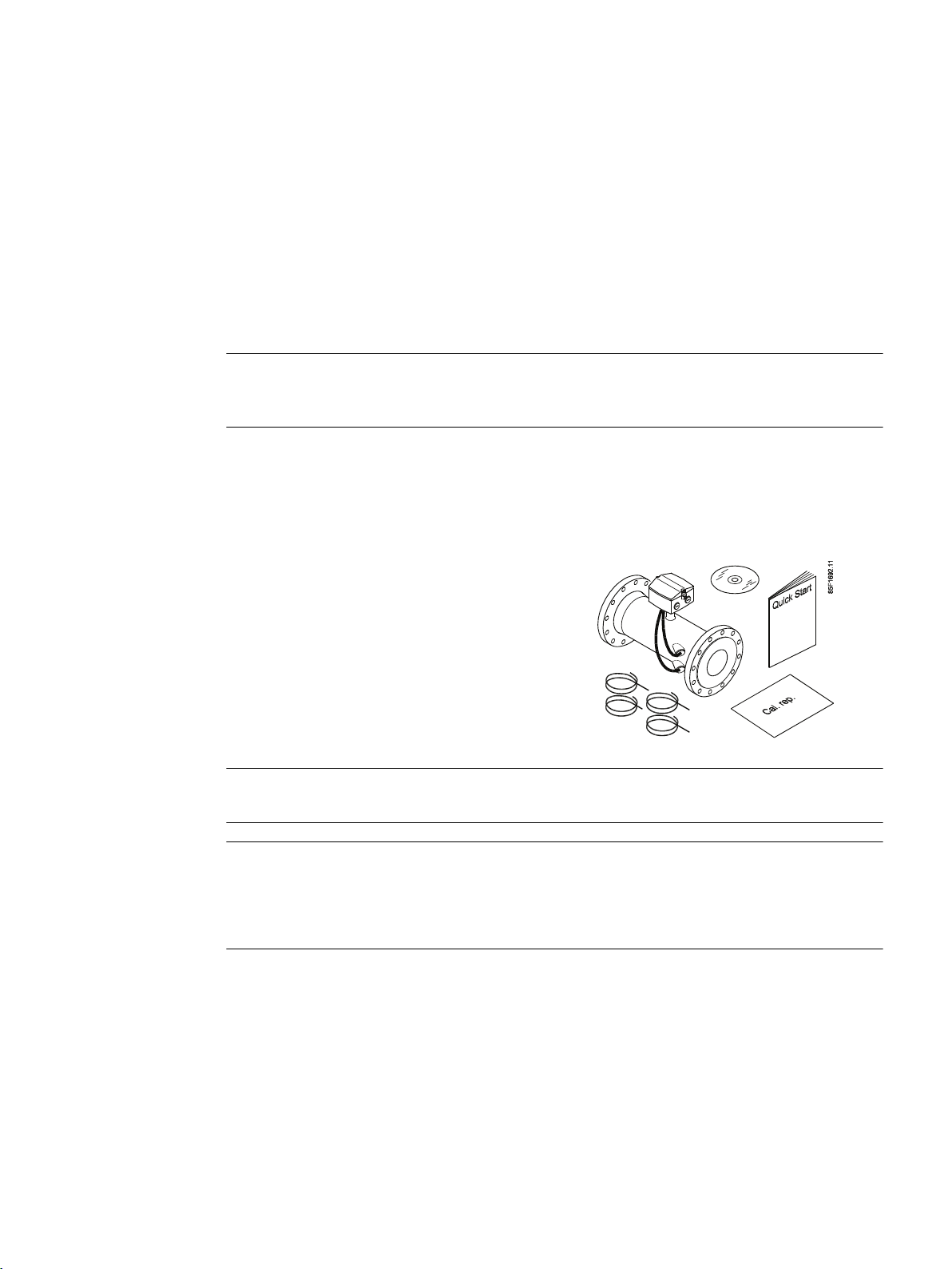
1.1 Items supplied
● SITRANS F US SONO 3300
● SITRANS F literature CD
● Quick Start guide
● Calibration report
● Transducer coaxial cable (4 pcs)
● Transmitter type FUS060 (not shown)
1
Note
Scope of delivery may vary, depending on version and add-ons.
Note
Handle with care!
Impact and shock can damage the piezeoelectric crystal located in the transducers.
Do not stress or bend the tubes with transducer cables.
1.2 History
The contents of these instructions are regularly reviewed and corrections are included in
subsequent editions. We welcome all suggestions for improvement.
SITRANS F US SONO 3300
Operating Instructions, 01/2010, SFIDK.PS.029.J4.02 5

Introduction
1.3 Further Information
The following table shows the most important changes in the documentation compared to each
previous edition.
Edition Remarks
01/2006 SITRANS F US Ultrasonic flowmeter Sensor type SONO 3300 DN 50 ... DN 300 for use
03/2008 Version 2.
08/2009 Version 3. Contents restructured.
Note
A flowmeter system consists of a sensor (SONO 3300) and a transmitter (FUS060).
These Operating Instructions only cover the sensor part of the system. The transmitter FUS060
has a separate manual, which is available on the SITRANS F literature CD-ROM and on the
flow documentation homepage (http://www.siemens.com/flowdocumentation)
with transmitter type FUS060 (Operating Instructions, replacing SITRANS F US SONO‐
FLO Handbook)
1.3 Further Information
The contents of these Operating Instructions shall not become part of or modify any prior or
existing agreement, commitment or legal relationship. All obligations on the part of Siemens AG
are contained in the respective sales contract which also contains the complete and solely
applicable warranty conditions. Any statements contained herein do not create new warranties
or modify the existing warranty.
Product information on the Internet
The Operating Instructions are available on the CD-ROM shipped with the device, and on the
Internet on the Siemens homepage, where further information on the range of SITRANS F
flowmeters may also be found:
Product information on the internet (http://www.siemens.com/flow)
Worldwide contact person
If you need more information or have particular problems not covered sufficiently by the
operating instructions, please get in touch with your contact person. You can find contact
information for your local contact person on the Internet:
Local contact person (http://www.automation.siemens.com/partner)
SITRANS F US SONO 3300
6 Operating Instructions, 01/2010, SFIDK.PS.029.J4.02
Safety notes
CAUTION
Correct, reliable operation of the product requires proper transport, storage, positioning and
assembly as well as careful operation and maintenance. Only qualified personnel should
install or operate this instrument.
Note
Alterations to the product, including opening or improper repairs of the product, are not
permitted.
If this requirement is not observed, the CE mark and the manufacturer's warranty will expire.
2.1 Laws and directives
General requirements
2
Installation of the equipment must comply with national regulations. For example EN 60079-14
for the European Community.
Instrument safety standards
The device has been tested at the factory, based on the safety requirements. In order to
maintain this condition over the expected life of the device the requirements described in these
Operating Instructions must be observed.
NOTICE
Material compatibility
The meters have been designed according to EN 13480 with an additional corrosion layer of
approx. 1 mm for steel sensors. Stainless steel transducer parts do not have an additional
layer.
It is the responsibility of the customer to ensure that the medium is compatible with the sensor
construction material. The full responsibility for the selection rests with the customer and
Siemens Flow Instruments can take no responsibility for any failure due to material
incompatibility.
SITRANS F US SONO 3300
Operating Instructions, 01/2010, SFIDK.PS.029.J4.02 7
Safety notes
2.2 Installation in hazardous area
CE marked equipment
The CE-mark symbolizes the compliance of the device with the following directives:
● EMC directive 2004/108/EC
● Low voltage directive 2006/95/EC
● Pressure equipment directive (PED/DGRL) 93/23/EC
● ATEX Directive 94/9/EC
2.2 Installation in hazardous area
WARNING
Equipment used in hazardous areas must be Ex-approved and marked accordingly. It is
required that the special conditions for safe use provided in the manual and in the Ex
certificate are followed!
Hazardous area approvals
This flowmeter (SONO 3300 with FUS060) is approved for use in hazardous area and has the
following approval:
● ATEX II 2G Ex dem [ia/ib] IIC T6/T4/T3
The sensor part of the flowmeter (SONO 3300) furthermore has the following approval:
● ATEX II 2G Ex ib IIC T6/T4/T3 (only approved for use with FUS060)
WARNING
Make sure the hazardous area approval is suitable for the environment in which the device
will be installed.
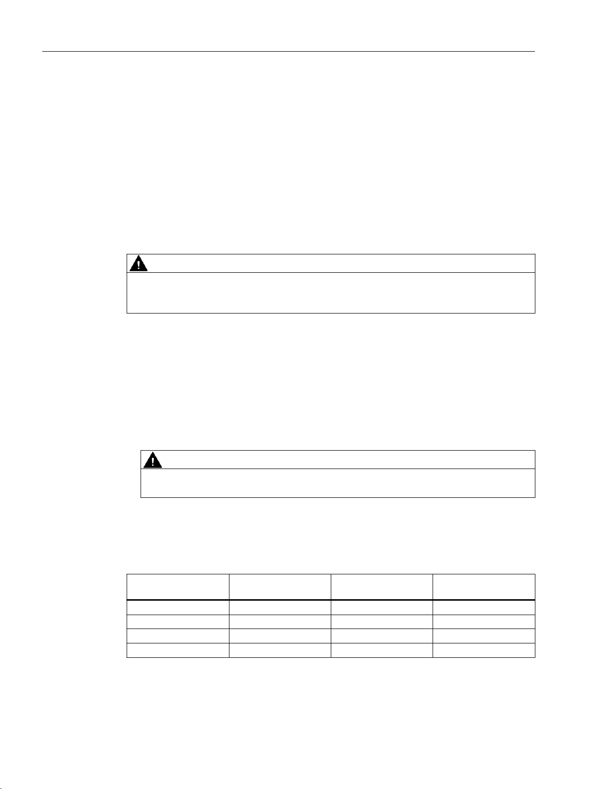
Temperature specifications for use in hazardous area
Table 2-1 Hazardous area temperature specifications
Temperature class Max. surface tempera‐
ture
T3 +200°C +135 ... 200°C
T4 +135°C +100 ... 135°C -20 ... +60°C
T5 +100°C +85 ... 100°C -20 ... +60°C
T6 +85°C -10 ... 85°C -20 ... +60°C
1)
Maximum media temperature technically limited to +160°C
Media temperature Ambient temperature
1)
-20 ... +60°C
SITRANS F US SONO 3300
8 Operating Instructions, 01/2010, SFIDK.PS.029.J4.02
WARNING
Media temperature specifications
Make sure that media temperature specifications indicated on the device type plate / label will
not be exceeded.
Hazardous area safety requirements
WARNING
It is required that:
● Electrical connections are in accordance with EN60079-14 (Installing Electrical Systems in
Explosion Hazardous Areas).
● Appropriate cable connectors are used for the output circuits:
– Intrinsically safe: blue and / or metal (nickle plated brass)
– Non-intrinsically safe: gray or black
● Protective earth terminals (PE) on both sensor and transmitter are connected (min. 4mm2).
Safety notes
2.2 Installation in hazardous area
SITRANS F US SONO 3300
Operating Instructions, 01/2010, SFIDK.PS.029.J4.02 9

Safety notes
2.2 Installation in hazardous area
SITRANS F US SONO 3300
10 Operating Instructions, 01/2010, SFIDK.PS.029.J4.02
Description
SITRANS F US ultrasonic flowmeters measure flow in standard volumetric units. Measurement
is independent of changes in liquid temperature, density, pressure and conductivity. A time of
flight flowmeter is designed for use on single phase liquids.
They are designed for measurement of:
● Volume flow rate
● Limit monitoring
● Total volume
● Sound velocity in the media
3.1 Measuring principle
Physical principle
3
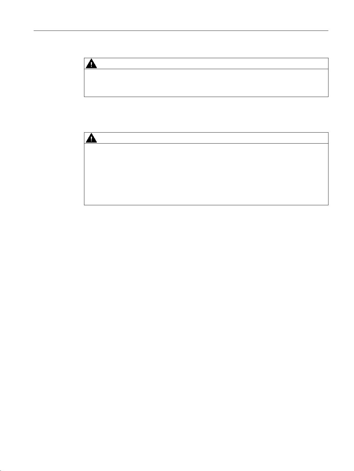
Figure 3-1 Velocity distribution along sound path
A sound wave travelling in the same direction as the liquid flow arrives at point B from point A
in a shorter time than the sound wave travelling against the direction of flow (from point B to A).
The difference in sound transit time indicates the flow velocity in the pipe.
Since delay time is measured at short intervals both in and against flow direction, temperature
has no influence on measurement accuracy.
SITRANS F US flowmeters
In SITRANS F US flowmeters the ultrasonic transducers are placed at an angle θ in relation to
the pipe axis. The transducers function as transmitters and receivers of the ultrasonic signals.
Measurement is performed by determining the time the ultrasonic signal takes to travel with and
against the flow. The principle can be expressed as follows:
v = K × (t
v = Average flow velocity
SITRANS F US SONO 3300
Operating Instructions, 01/2010, SFIDK.PS.029.J4.02 11
B,A
– t
A,B
) / (t
A,B
× t
B,A
) = K × Δt/t²
1A
1B
Description
3.2 Design
t = Transit time
K = Proportional flow factor
This measuring principle offers the advantage that it is independent of variations in the actual
sound velocity of the liquid, i.e. independent of the temperature.
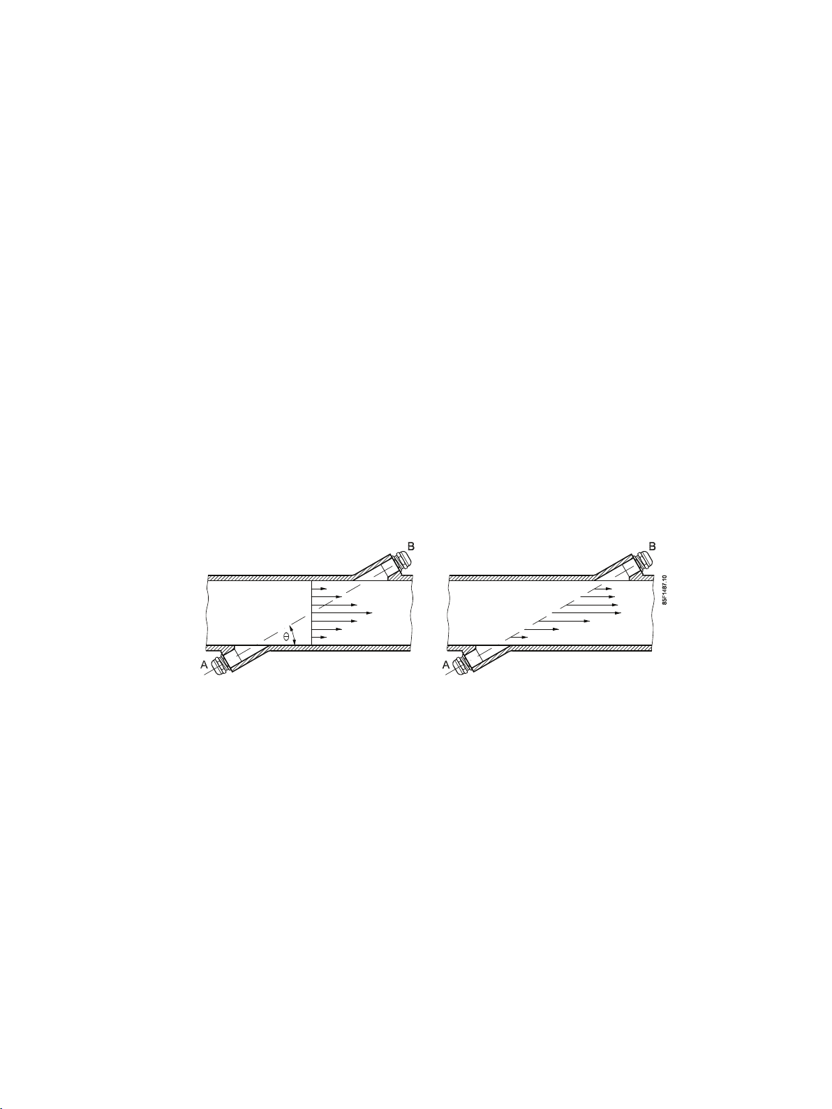
The Proportional factor K is determined by wet calibration or calculated by "Auto" in case of
manual programming of mechanical geometrical pipe data (SONOKIT only). The transducer
angle (Θ), distance between sensors (L) and pipe dimension (Di) are shown in the figure below.
Figure 3-2 Measuring principle
The ultrasonic signal is sent directly between the transducers. The advantage gained sending
signals from point to point is an extremely good signal strength.
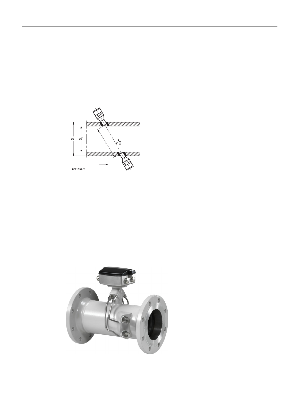
3.2 Design
SITRANS F US SONO 3300 with FUS060 is designed for measuring the flow velocity of liquids
in full pipes. Satisfactory function of the ultrasonic flowmeter depends on a low sound
attenuation of the medium and a well-defined and stable flow profile.
The sensor SONO 3300 with transmitter FUS060 remote mounted measures with a high
accuracy (better than ±0,5% of reading over a wide measuring range).
Figure 3-3 SITRANS F US SONO 3300 (shown without transmitter type FUS060)
SITRANS F US SONO 3300
12 Operating Instructions, 01/2010, SFIDK.PS.029.J4.02
 Loading...