

Siemens SITRANS F M TRANSMAG 2 Operating Instructions Manual

Electromagnetic Flowmeters
SITRANS F M TRANSMAG 2
Operating Instructions • 11/2009
SITRANS F


Introduction
1
Safety notes
2
Description
3
Installing
4
Connecting
5
Commissioning
6
Functions
7
Service and Maintenance
8
Troubleshooting
9
Technical data
10
Parameters
A
Profibus Communication
B
Appendix
C
SITRANS F
Flowmeters
SITRANS F M TRANSMAG 2
Operating Instructions
11/2009
A5E00102775-07

Legal information
Warning notice system
This manual contains notices you have to observe in order to ensure your personal safety, as well as to prevent
damage to property. The notices referring to your personal safety are highlighted in the manual by a safety alert
symbol, notices referring only to property damage have no safety alert symbol. These notices shown below are
graded according to the degree of danger.
DANGER
indicates that death or severe personal injury will result if proper precautions are not taken.
WARNING
indicates that death or severe personal injury may result if proper precautions are not taken.
CAUTION
with a safety alert symbol, indicates that minor personal injury can result if proper precautions are not taken.
CAUTION
without a safety alert symbol, indicates that property damage can result if proper precautions are not taken.
NOTICE
indicates that an unintended result or situation can occur if the corresponding information is not taken into
account.
If more than one degree of danger is present, the warning notice representing the highest degree of danger will
be used. A notice warning of injury to persons with a safety alert symbol may also include a warning relating to
property damage.
Qualified Personnel
The product/system described in this documentation may be operated only by personnel qualified for the specific
task in accordance with the relevant documentation for the specific task, in particular its warning notices and
safety instructions. Qualified personnel are those who, based on their training and experience, are capable of
identifying risks and avoiding potential hazards when working with these products/systems.
Proper use of Siemens products
Note the following:
WARNING
Siemens products may only be used for the applications described in the catalog and in the relevant technical
documentation. If products and components from other manufacturers are used, these must be recommended
or approved by Siemens. Proper transport, storage, installation, assembly, commissioning, operation and
maintenance are required to ensure that the products operate safely and without any problems. The permissible
ambient conditions must be adhered to. The information in the relevant documentation must be observed.
Trademarks
All names identified by ® are registered trademarks of the Siemens AG. The remaining trademarks in this
publication may be trademarks whose use by third parties for their own purposes could violate the rights of the
owner.
Disclaimer of Liability
We have reviewed the contents of this publication to ensure consistency with the hardware and software
described. Since variance cannot be precluded entirely, we cannot guarantee full consistency. However, the
information in this publication is reviewed regularly and any necessary corrections are included in subsequent
editions.
Siemens AG
Industry Sector
Postfach 48 48
90026 NÜRNBERG
GERMANY
Ordernumber: A5E00102775
Ⓟ 11/2009
Copyright © Siemens AG 2009.
Technical data subject to change

SITRANS F M TRANSMAG 2
Operating Instructions, 11/2009, A5E00102775-07
3
Table of contents
1 Introduction................................................................................................................................................ 5
1.1 Preface...........................................................................................................................................5
1.2 Items supplied................................................................................................................................5
1.3 History............................................................................................................................................5
1.4 Further Information ........................................................................................................................6
2 Safety notes............................................................................................................................................... 7
2.1 General safety instructions ............................................................................................................7
2.2 Laws and directives .......................................................................................................................7
3 Description................................................................................................................................................. 9
3.1 Overview ........................................................................................................................................9
3.2 Operating principle.........................................................................................................................9
3.3 Features.......................................................................................................................................10
3.4 BUS Communication....................................................................................................................11
4 Installing .................................................................................................................................................. 13
4.1 General Information .....................................................................................................................13
4.2 Sensor installation........................................................................................................................14
4.2.1 Potential equalization of sensor (refence potential).....................................................................18
4.3 Turning the local display ..............................................................................................................19
4.4 Transmitter installation (remote version) .....................................................................................20
4.4.1 Wall mounting with standard mounting plate ...............................................................................20
4.4.2 Pipe or wall mounting with assembly bracket..............................................................................21
5 Connecting .............................................................................................................................................. 23
5.1 General Information .....................................................................................................................23
5.2 Step 1: Connecting power supply ................................................................................................25
5.3 Step 2: Connecting signal cables ................................................................................................26
5.4 Step 3: Connecting terminal box and transmitter.........................................................................27
6 Commissioning ........................................................................................................................................ 31
6.1 Operating Transmag 2.................................................................................................................31
6.2 Write protection............................................................................................................................34
6.3 Language and illumination...........................................................................................................35
6.4 Operating examples.....................................................................................................................35
7 Functions................................................................................................................................................. 39
7.1 Menu structure .............................................................................................................................39

Table of contents
SITRANS F M TRANSMAG 2
4 Operating Instructions, 11/2009, A5E00102775-07
7.2 Function Group Display............................................................................................................... 39
7.3 Function Group Diagnostics........................................................................................................ 40
7.4 Function Group Measuring Functions......................................................................................... 43
7.5 Function Group Device Outputs.................................................................................................. 50
7.6 Function Group Identification ...................................................................................................... 57
7.7 Function Group Service .............................................................................................................. 58
8 Service and Maintenance ........................................................................................................................ 61
8.1 Maintenance................................................................................................................................ 61
8.2 Cleaning ...................................................................................................................................... 61
8.3 Changing fuses ........................................................................................................................... 61
8.4 Recalibration ............................................................................................................................... 62
8.5 Technical support........................................................................................................................ 63
8.6 Return procedures ...................................................................................................................... 64
9 Troubleshooting....................................................................................................................................... 65
9.1 Quick sensor check-up................................................................................................................ 65
9.2 Application Problems .................................................................................................................. 66
9.3 Error messages........................................................................................................................... 68
9.4 Application information guide...................................................................................................... 69
10 Technical data ......................................................................................................................................... 73
10.2 Dimensions ................................................................................................................................. 76
A Parameters.............................................................................................................................................. 79
B Profibus Communication.......................................................................................................................... 91
B.1 PROFIBUS Communication........................................................................................................ 91
B.2 Wiring devices with Profibus PA ................................................................................................. 92
B.3 Cyclic Data Traffic ....................................................................................................................... 93
B.4 Input Data (from Slave to Master)............................................................................................... 94
B.5 Output Data (from Master to Slave) ............................................................................................ 96
B.6 Diagnostics.................................................................................................................................. 97
B.7 Locking operation.........................................................................................................
............... 99
B.8 Device Database File (GSD)..................................................................................................... 100
B.9 Literature list.............................................................................................................................. 104
C Appendix................................................................................................................................................ 107
C.1 Certificates ................................................................................................................................ 107
C.2 Accessories and spare parts..................................................................................................... 107
Index...................................................................................................................................................... 109
SITRANS F M TRANSMAG 2
Operating Instructions, 11/2009, A5E00102775-07
5
Introduction
1
1.1 Preface
These instructions contain all the information you need for using the device.
The instructions are aimed at persons mechanically installing the device, connecting it
electronically, configuring the parameters and commissioning it as well as service and
maintenance engineers.
Note
It is the responsibility of the customer that the instructions and directions provided in the
manual are read, understood and followed by the relevant personnel before installing the
device.
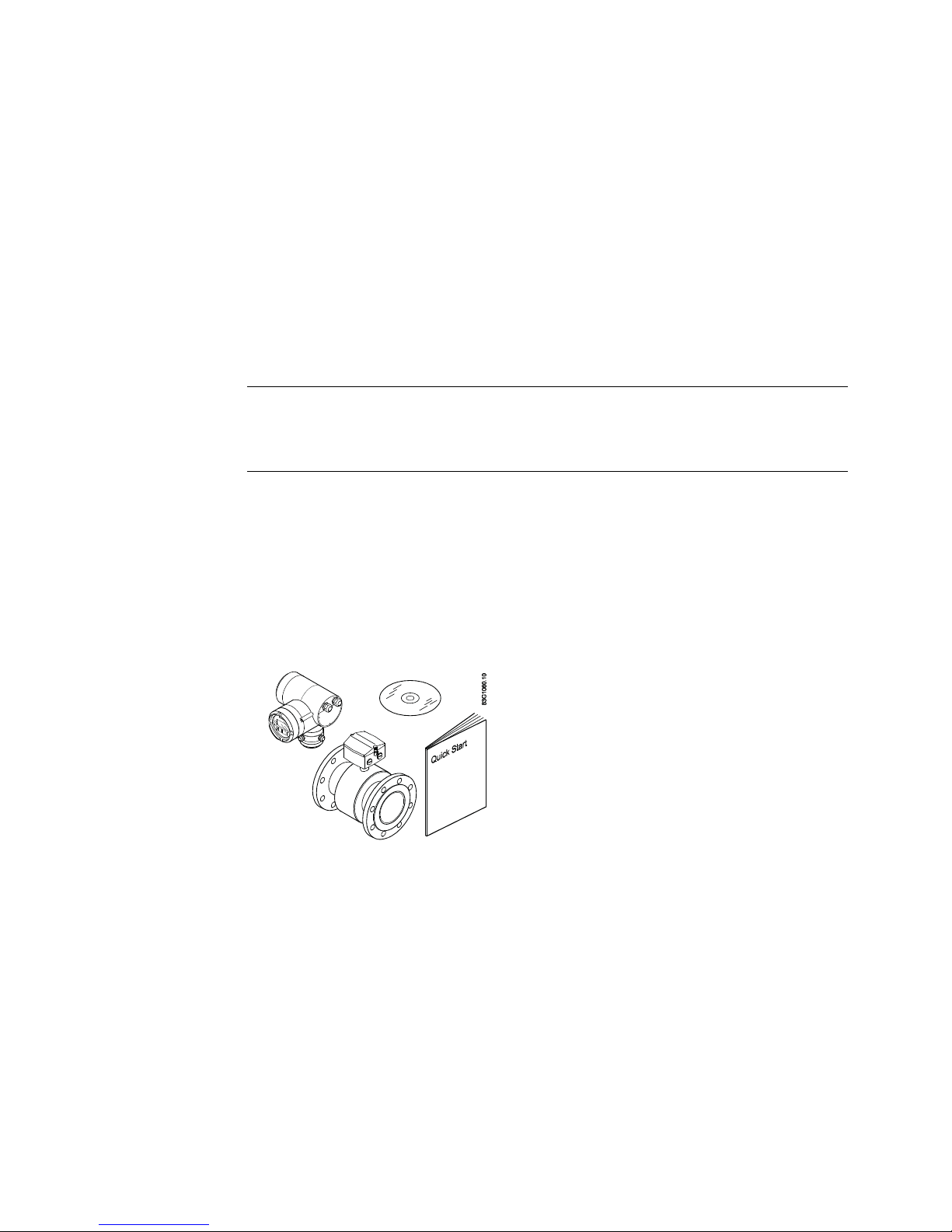
1.2 Items supplied
● SITRANS F M Transmag 2
● Wall mounting kit (remote only)
● Cable glands (remote only)
● Ferrite cores
1.3 History
The contents of these instructions are regularly reviewed and corrections are included in
subsequent editions. We welcome all suggestions for improvement.
The following table shows the most important changes in the documentation compared to
each previous edition.

Introduction
1.4 Further Information
SITRANS F M TRANSMAG 2
6 Operating Instructions, 11/2009, A5E00102775-07
Edition Remarks
02/2008 Transmag / Intermag
02/2008 Transmag
• All information concerning Intermag has been removed.
02/2009 Transmag 2 Op. Instr.
The most important changes are:
• Restructering of contents.
1.4 Further Information
The contents of these Operating Instructions shall not become part of or modify any prior or
existing agreement, commitment or legal relationship. All obligations on the part of Siemens
AG are contained in the respective sales contract which also contains the complete and
solely applicable warranty conditions. Any statements contained herein do not create new
warranties or modify the existing warranty.
Product information on the Internet
The Operating Instructions are available on the CD-ROM shipped with the device, and on
the Internet on the Siemens homepage, where further information on the range of SITRANS
F flowmeters may also be found:
Product information on the internet (http://www.siemens.com/flowdocumentation
)
Worldwide contact person
If you need more information or have particular problems not covered sufficiently by the
operating instructions, please get in touch with your contact person. You can find contact
information for your local contact person on the Internet:
Local contact person (http://www.automation.siemens.com/partner
)

SITRANS F M TRANSMAG 2
Operating Instructions, 11/2009, A5E00102775-07
7
Safety notes
2
2.1 General safety instructions
CAUTION
Correct, reliable operation of the product requires proper transport, storage, positioning and
assembly as well as careful operation and maintenance. Only qualified personnel should
install or operate this instrument.
Note
Alterations to the product, including opening or improper repairs of the product, are not
permitted.
If this requirement is not observed, the CE mark and the manufacturer's warranty will expire.
2.2 Laws and directives
General requirements
Installation of the equipment must comply with national regulations. For example EN 6007914 for the European Community.
Instrument safety standards
The device has been tested at the factory, based on the safety requirements. In order to
maintain this condition over the expected life of the device the requirements described in
these Operating Instructions must be observed.
It generally applies for electrical installation:
● Use heat-resistant cables if high temperatures occur on the housing, e.g. due to heat
conductance from the sensor/measuring pipe. Ensure that the cables do not touch the hot
sensor tube.
CE-marked equipment
The CE mark symbolizes the compliance of the device with the following guidelines:
● EMC guideline 89/336/EWG
● Low voltage guideline 73/23/EWG
● Pressure equipment directive (PED/DGRL) 93/23/EG
The SITRANS F M magnetic-inductive measuring devices comply with protection class I.

Safety notes
2.2 Laws and directives
SITRANS F M TRANSMAG 2
8 Operating Instructions, 11/2009, A5E00102775-07

SITRANS F M TRANSMAG 2
Operating Instructions, 11/2009, A5E00102775-07
9
Description
3
3.1 Overview
SITRANS F M Transmag 2 is a pulsed alternating field magnetic flowmeter where the
magnetic field strength is much higher than conventional DC pulsed magnetic flowmeters.
This makes it ideal for difficult applications as:
● High concentrated paper stock > 3 %
● Heavy mining slurries
● Mining slurries with magnetic particles
The complete flowmeter consists of a flow sensor 911/E and the associated SITRANS F M
Transmag 2 transmitter.
Transmag 2 is available in a remote or a compact version. The 911/E sensor is available
with diameters from DN 15 to DN 600 (½" to 24").
As a standard protective washers are fitted permanently on all PTFE-coated sensors to
protect the coating.
3.2 Operating principle
SITRANS F M Transmag 2 is a microprocessor-based transmitter with a built-in
alphanumeric display in several languages. The transmitters evaluate the signals from the
associated electromagnetic sensors and also fulfil the task of a power supply unit which
provides the magnet coils with a constant current.
The magnetic flux density in the sensor is additionally monitored by reference coils. Further
information on connection, mode of operation and installation can be obtained from the
sensor data sheets.
Figure 3-1 SITRANS F M Transmag 2 magnetic-inductive flow transmitter

Description
3.3 Features
SITRANS F M TRANSMAG 2
10 Operating Instructions, 11/2009, A5E00102775-07
3.3 Features
● Fast signal processing with 16-bit technology
● Automatic recognition of the sensor type and calibration data as result of SmartPLUG.
The SmartPLUG is a pre-amplifier in the sensor with integrated data module which
contains the stored factory data of the sensor and customer-specific data.
● PROFIBUS-PA (Profile 2.0) or HART communication
● Simple, multi-language menu-guided operation with two-line display and four optical input
elements
● Self-monitoring function
● Internal simulation for all input and output functions
● Monitoring of the sensor using magnetizing current and reference voltage as well as wet
electrode function
● Analog output and digital outputs for pulses, device status, limits, flow direction,
frequency output
● Optional passive switch input for resetting the counter values or for switching off the
measuring equipment (PZR)
● With pulsed alternating field for minimum conductivity of 0.1 μS/cm depending on the
sensor
● Split mode
● Parameters can be specifically selected and modified, e.g.:
– Operating parameters such as measuring range, physical dimensions or device
information
– Limits for flow, counter configurations
– Noise suppression using separate interference suppression and damping as well as
hysteresis functions
– Automatic mains synchronization
– Display parameters (freely configurable text display)
– Display in volume or mass units
– Density as constant input value for conversion of volume into mass
– Low flow cut-off
– Forward and reverse flow measurements
– Flow direction display and evaluation
– Diagnostics functions and control values
– PROFIBUS address
– Functions of analog output: proportional flow, failure signal
– Functions of digital output 1 (transistor): pulse output, frequency output proportional to
flow, alarm, forward or reverse flow signal, min. or max. limit for flow and counter
– Functions of digital output 2 (relay): alarm, forward or reverse flow signal, min. or max.
limit for flow and counter

Description
3.4 BUS Communication
SITRANS F M TRANSMAG 2
Operating Instructions, 11/2009, A5E00102775-07
11
– Simulation of output signal via analog output, digital output 1 and digital output 2
– Option: digital output 2 as digital input for resetting counter values or for interruption in
measurement (PZR)
3.4 BUS Communication
SITRANS F M Transmag 2 is available with HART or PROFIBUS communication.
● The HART protocol is superimposed on the analog output (current output). This
communication capability permits parameterization of the device using the HART
communicator or a PC/laptop and SIMATIC PDM software in addition to local operation.
● In the PROFIBUS PA version, the analog output and the digital output 2 are replaced by
the digital PROFIBUS PA output. Parameterization of the device is then possible using
PROFIBUS communication and SIMATIC PDM in addition to local operation.

Description
3.4 BUS Communication
SITRANS F M TRANSMAG 2
12 Operating Instructions, 11/2009, A5E00102775-07

SITRANS F M TRANSMAG 2
Operating Instructions, 11/2009, A5E00102775-07
13
Installing
4
4.1 General Information
This chapter describes how to install the flowmeter in the compact version as well as in the
remote version.
CAUTION
The device meet the requirements of IP67 degree of protection. Proper installation is a
prerequisite for compliance with this degree of protection. Please observe the instructions
in this chapter.
The maximum permissible ambient and medium temperatures must be observed at all
times.
The measuring tube should be filled exclusively with media to which the seal and lining
materials are chemically resistant. Only conductive media are permissible.
WARNING
If the surface of the sensor or sensor tube can get hotter than 50 ºC in the application, fire
protection and/or a warning sign must be provided.
CAUTION
Make sure the measuring device is protected from direct sunlight when installing it
outdoors.
Installing
4.2 Sensor installation
SITRANS F M TRANSMAG 2
14 Operating Instructions, 11/2009, A5E00102775-07
4.2 Sensor installation
The measuring principle is generally independent of the flow profile unless static eddy
currents penetrate the measured value forming zone (e.g. after pipe elbows, in the case of
tangential occlusion or half open slides in front of the sensor). Measures to normalize the
flow profile are necessary in such cases. Suitable measures in this respect are:
● increasing the inlet and outlet lines
● using flow rectifiers
● reducing the line cross section
CAUTION
It is recommended to use protective rings (orifice protectors) to protect the inlet and
outlet edges of the sensor against mechanical damage especially when used with
abrasive media.
Protective rings are available as accessories.
Vertical/horizontal installation
Figure 4-1 Horizontal / vertical installation
Installing
4.2 Sensor installation
SITRANS F M TRANSMAG 2
Operating Instructions, 11/2009, A5E00102775-07
15
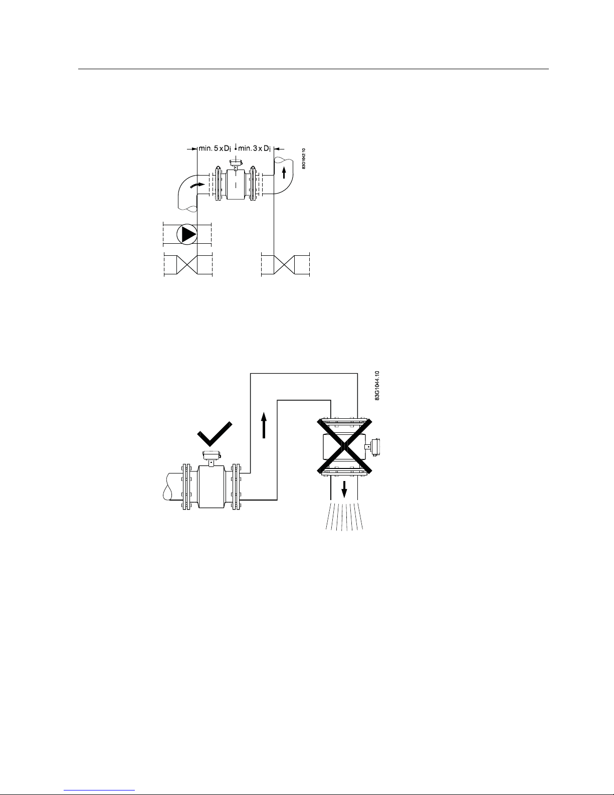
Inlet/outlet section
The inlet and outlet lines must be kept straight
Figure 4-2 Installation between pipe elbows, valves and pumps
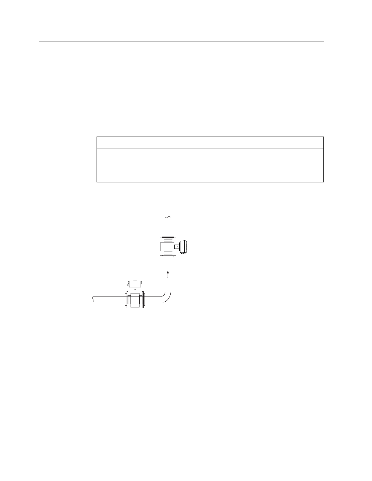
Sensor location
Do not install the sensor in pipe sections with a free pipe outlet which could run empty. When
installing in a downpipe, make sure that the pipe is always filled 100% with the medium
Figure 4-3 Installation in pipes without emptying
Installing
4.2 Sensor installation
SITRANS F M TRANSMAG 2
16 Operating Instructions, 11/2009, A5E00102775-07
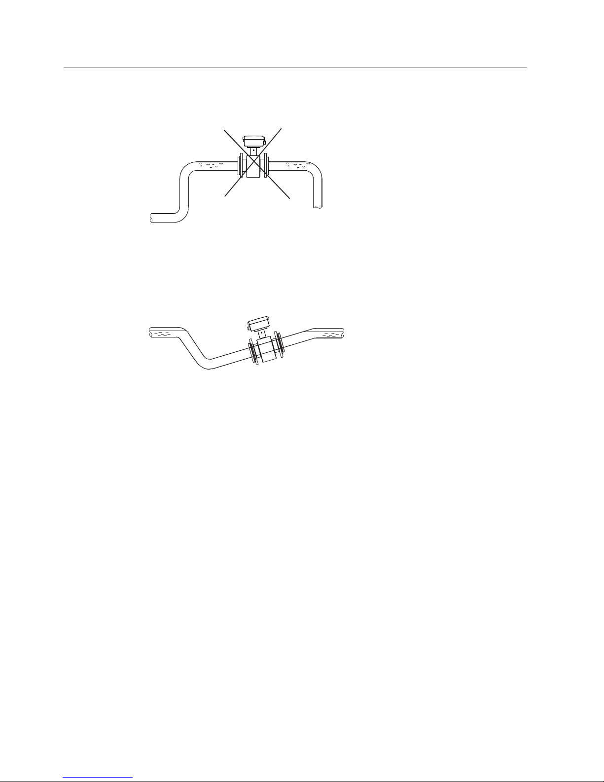
Avoid installation at the highest point of the pipe because of accumulation of gas
Figure 4-4 Installation at the highest point
Install the flowmeter so that the measuring pipe cannot run empty and is always filled with
medium.
The sensor must be installed in a culvert in the case of an unfilled pipe or only a free level
line (outlet).
Figure 4-5 Installation in a constantly filled pipe
Installing
4.2 Sensor installation
SITRANS F M TRANSMAG 2
Operating Instructions, 11/2009, A5E00102775-07
17
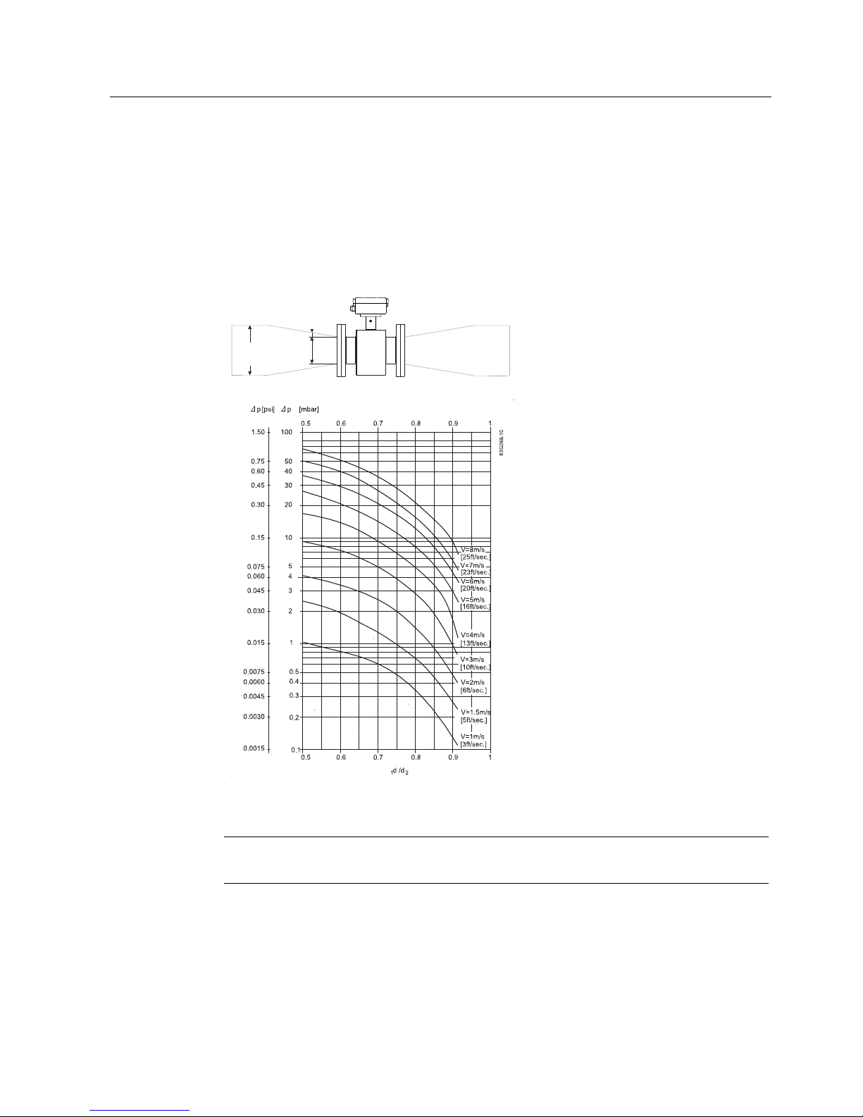
Line cross sections
By reducing line cross sections you have the possibility of installing smaller sensors in pipes
of larger rated widths.
This has the advantage that the speed in the sensor increases with small flows and thus a
better measuring accuracy is achieved.
To avoid the formation of eddy currents in the sensor, the angle of reduction should not be
greater than 8°.
<
8
°
d
A
d
R
d
1
d
2
<8°
Figure 4-6 Example of reduction of a line cross section
Note
Reductions cause losses in pressure.
Installing
4.2 Sensor installation
SITRANS F M TRANSMAG 2
18 Operating Instructions, 11/2009, A5E00102775-07
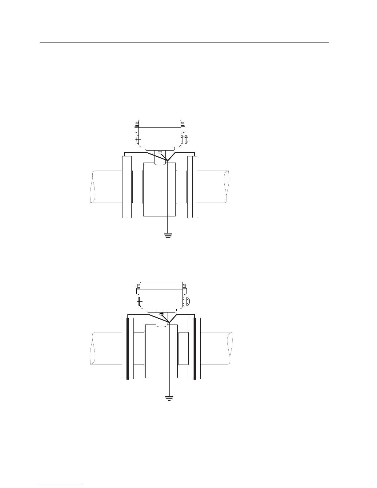
4.2.1 Potential equalization of sensor (refence potential)
The sensor must be at the same potential as the medium for an accurate measurement.
This is guaranteed when the connecting flange of the pipe is made of metal and a perfect
electrical connection is established to the sensor through the fastening screws. In this case
the medium, pipe and transmitter are connected with each other in the sense of a potential
equalization.
Figure 4-7 Reference potential in electrically conductive pipes
In the case of internally electrically isolated pipes, the medium in the pipe must be applied to
a reference potential by additional measures (e.g. by grounding rings). Grounding rings
serve to establish the reference potential of the sensor in electrically isolated pipes.
Figure 4-8 Reference potential in electrically isolated pipes by grounding rings
Grounding rings are offered as accessories.
Installing
4.3 Turning the local display
SITRANS F M TRANSMAG 2
Operating Instructions, 11/2009, A5E00102775-07
19
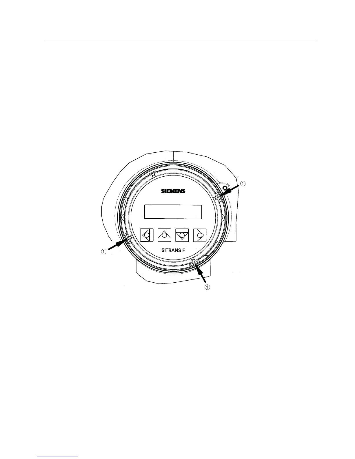
4.3 Turning the local display
The local display can be turned in 90° steps to enable better reading in case of vertical
installation or overhead assembly.
1. Switch off the power supply.
2. Release the catch on the lid of the electronics compartment with a 3 mm Allen key.
3. Unscrew the cover.
4. Carefully release the fastening hooks of the local display using a screwdriver or similar
tool
5. Pull out the unit, turn it to the desired position and push it back in.
6. Screw the lid back on and mount the lid catch.
① Fastening hooks
Figure 4-9 Unlocking the fastening hooks on the local display
Installing
4.4 Transmitter installation (remote version)
SITRANS F M TRANSMAG 2
20 Operating Instructions, 11/2009, A5E00102775-07
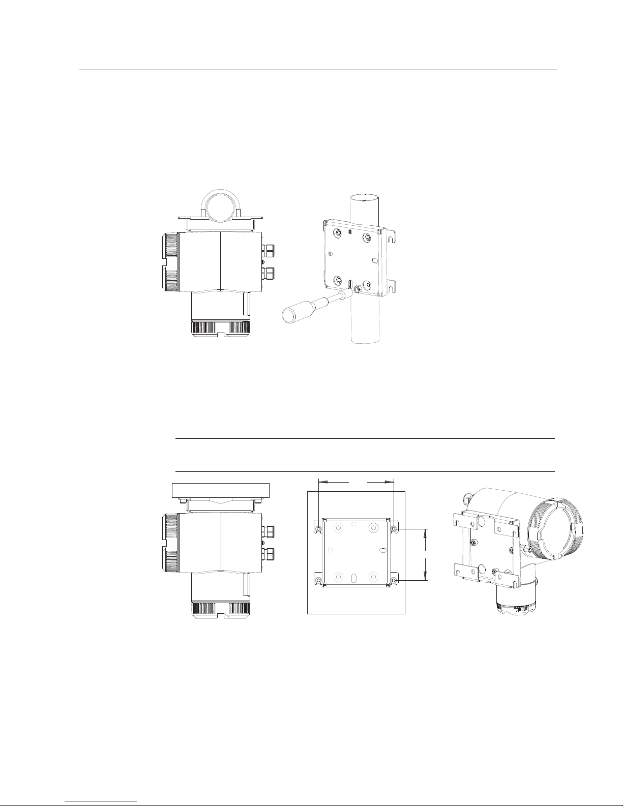
4.4 Transmitter installation (remote version)
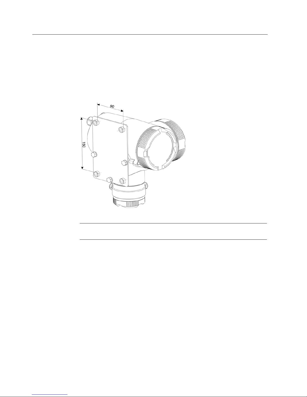
4.4.1 Wall mounting with standard mounting plate
1. Fit the mounting plate on the transmitter using the mounting material provided
2. Mount transmitter with mounting plate on the wall.
Figure 4-10 Standard mounting plate
Note
The standard mounting plate is only suitable for wall mounting.
Installing
4.4 Transmitter installation (remote version)
SITRANS F M TRANSMAG 2
Operating Instructions, 11/2009, A5E00102775-07
21
4.4.2 Pipe or wall mounting with assembly bracket
Pipe mounting
1. Mount the assembly bracket on the pipe using the fastening brackets
2. Fasten the transmitter with the two screws provided.
Pipe mounting with assembly bracket
Wall mounting
1. Fasten the asembly bracket to the back of the transmitter
2. Fasten the transmitter and assembly bracket to the wall
Note
The fastening brackets and nuts are not needed for wall mounting.
154
105
Wall mounting with assembly bracket

Installing
4.4 Transmitter installation (remote version)
SITRANS F M TRANSMAG 2
22 Operating Instructions, 11/2009, A5E00102775-07
SITRANS F M TRANSMAG 2
Operating Instructions, 11/2009, A5E00102775-07
23
Connecting
5
5.1 General Information
This chapter describes how to wire up the device.
Step 1 (Connecting power supply (Page 25)) and step 2 (Connecting signal cables
(Page 26)) must be carried out for compact as well as remote versions.
Step 3 (Connecting terminal box and transmitter (Page 27)) is only relevant for remote
versions.
The chapter only describes wiring of devices with HART. In order to wire up devices with
Profibus PA, refer to the Appendix:
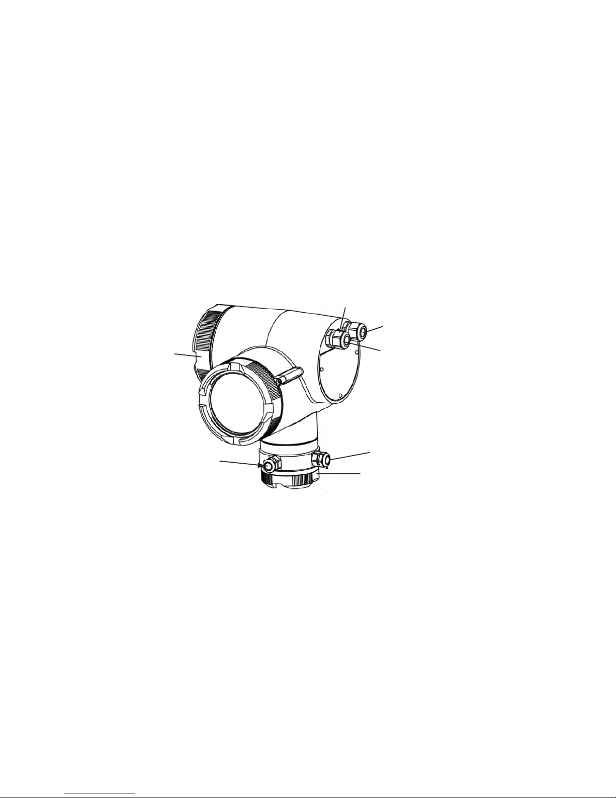
1
2
3
4
5
6
7
① Magnetic current line
② Terminal box for power supply and signal lines
③ Potential equalization
④ Signal line
⑤ Power supply
⑥ Electrode line
⑦ Terminal box for magnetic current and electrode line
Figure 5-1 Overview, Electrical connections
Connecting
5.1 General Information
SITRANS F M TRANSMAG 2
24 Operating Instructions, 11/2009, A5E00102775-07
WARNING
The pertinent regulations must be observed for electrical installation.
Never install the device with the mains voltage switched on!
Danger of electric shock!
The electrodes and magnetic current line may only be connected when the device is not
connected to the power supply.
Housing covers may only be unscrewed by qualified personnel when the housing is under
voltage (power supply).
Cable specifications
● Only use cables with at least the same degree of protection as the sensor to install the
sensor.
● The line length from the cable gland to the terminals must be kept as short as possible.
Line loops in the terminal box must be avoided.
● To guarantee the IP 67 degree of protection, use cables with the following external
diameters:
The permissible external diameter for auxiliary power and signal cable (large terminal
box) of the standard device (7ME5034-xxxxx-xAA0) is 6 to 12 mm.
Magnetic field current and electrode cable (small terminal box, only remote model):
– Cable glands M16 x 1.5 6 to 10 mm
– Cable glands 1/2" NPT 5 to 9 mm
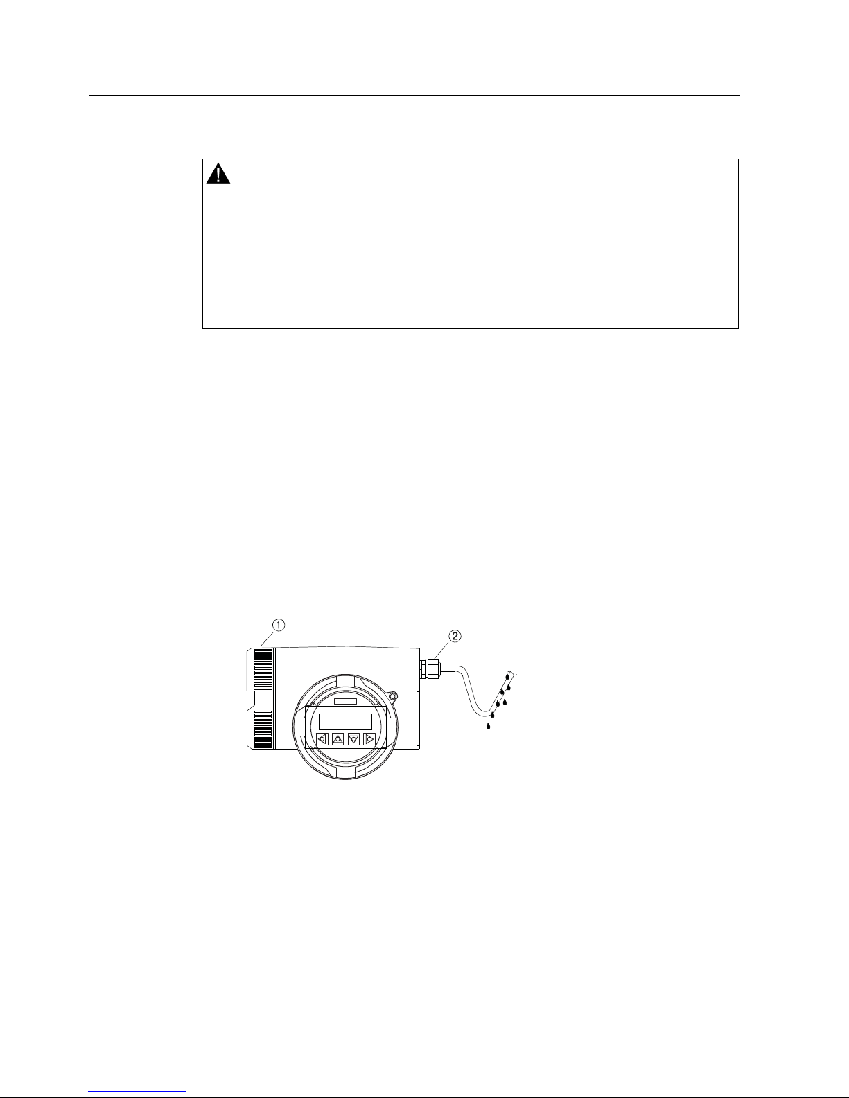
① Lid of terminal box
② Cable gland
Figure 5-2 Example of lazing cables before connecting the lines
See also
Wiring devices with Profibus PA (Page 92)
Connecting
5.2 Step 1: Connecting power supply
SITRANS F M TRANSMAG 2
Operating Instructions, 11/2009, A5E00102775-07
25
5.2 Step 1: Connecting power supply
CAUTION
Only connect the device to the supply which matches the specifications on the rating plate.
Connect the power supply by an easily accessible and appropriately labelled isolating
device and fuse (max. 4 A) or an easily accessible circuit breaker (max. 4 A).
Note
Use cables with a cross section of at least 1.5 mm
2
and double or reinforced insulation for
the power supply.
Wiring guidelines
1. Release the catch on the lid of the terminal box using a 3 mm Allen key.
2. Unscrew the lid of the terminal box.
3. Push the supply cable through the cable glands up to the terminal strip. Lay the cable in a
loop before the cable glands so that moisture does not get inside the terminal box.
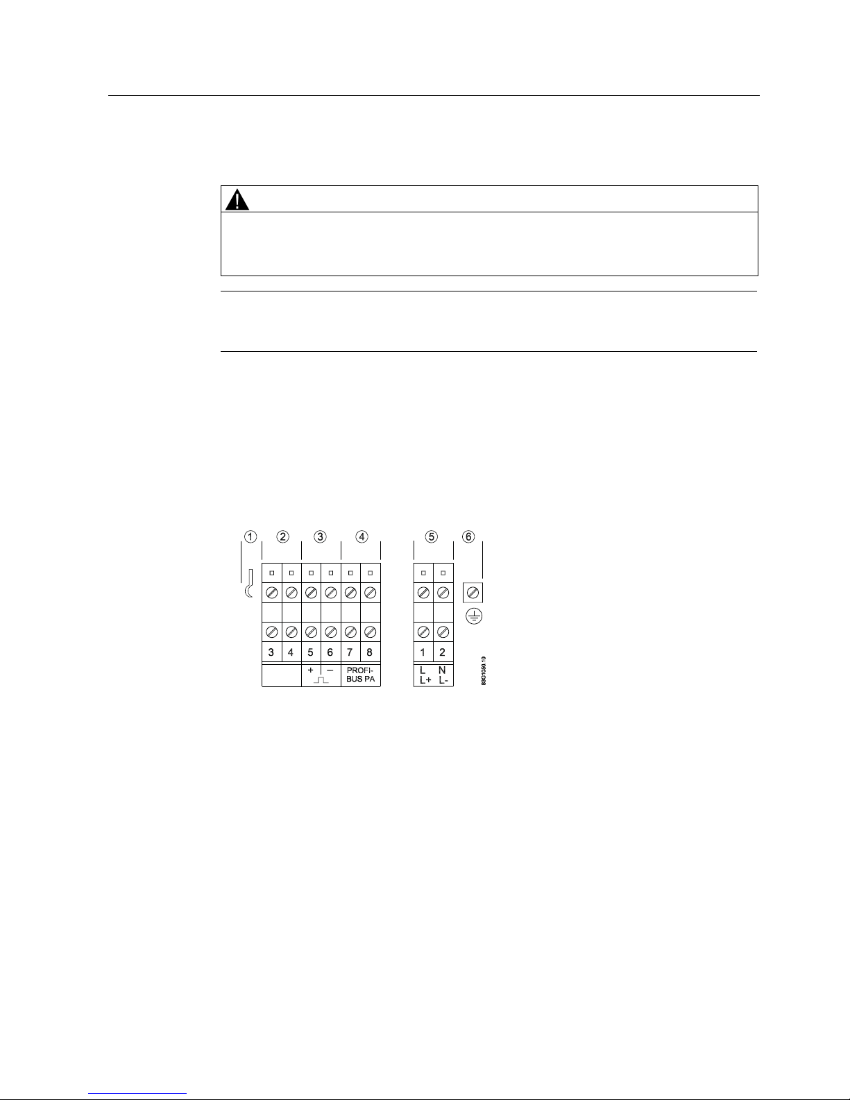
4. Connect the lines according to the figure below.
① Ground connection for signal cable shield
② Digital output 2 (relay) or digital input
③ Digital output 1 (active/passive)
④ Analog output (active) 4 to 20 mA resp. PROFIBUS
⑤ Power supply: L/N for 100 to 230 V AC
⑥ Terminal for PE conductor
Figure 5-3 Connection diagram for power supply and signal cables

Connecting
5.3 Step 2: Connecting signal cables
SITRANS F M TRANSMAG 2
26 Operating Instructions, 11/2009, A5E00102775-07
5.3 Step 2: Connecting signal cables
CAUTION
Lay the signal cables separately from cables with voltages > 60 V.
Avoid laying signal cables close to large electrical installations or use - if possible - only
shielded cables.
Note
In a wet environment, the signal cable for digital output 2 (terminals 3 and 4) must be
isolated when the feed-in voltage is more than AC 16V / DC 35 V.
Only use signal cables with twisted wire pairs.
1. Push the signal cable through the cable gland up to the terminal strip. Lay the cable in a
loop before the cable glands so that moisture does not get inside the terminal box.
2. Connect the lines according to the figure above.
3. Fit end ferrules to fine-wire lines.
4. Tighten the cable gland and check strain relief.
5. Screw the lid to the housing and tighten it. You must not use any tools. The sealing ring
must be clean and undamaged.
6. Mount the lid catch.
7. For transmitters in remote design, also connect the housing to the local potential
equalization to which the appropriate sensor must also be connected.
HART requirements
● The full HART 5.1 specification only applies when using shielded cables.
● Use signal cables with twisted wire pairs if the analog output and pulse/frequency output
are used simultaneously and signals are transmitted in one cable.
● A load of at least 250 Ω must exist in the signal circuit (see also Technical data
(Page 73)) for error free communication via the HART protocol.
See also
Wiring devices with Profibus PA (Page 92)

Connecting
5.4 Step 3: Connecting terminal box and transmitter
SITRANS F M TRANSMAG 2
Operating Instructions, 11/2009, A5E00102775-07
27
5.4 Step 3: Connecting terminal box and transmitter
WARNING
The SITRANS F M Transmag 2 transducer may only be connected to measuring sensor for
alternating fields SITRANS F M 911/E .
The magnetic circuit carries dangerous mains voltage.
As long as the device is under voltage, the lid of the housing on the sensor connection area
may only be opened by qualified personnel.
Before removing the terminal cover, the auxiliary power must be switched off from all poles.
Following installation, the terminal cover must be screwed back on again.
Connecting
5.4 Step 3: Connecting terminal box and transmitter
SITRANS F M TRANSMAG 2
28 Operating Instructions, 11/2009, A5E00102775-07
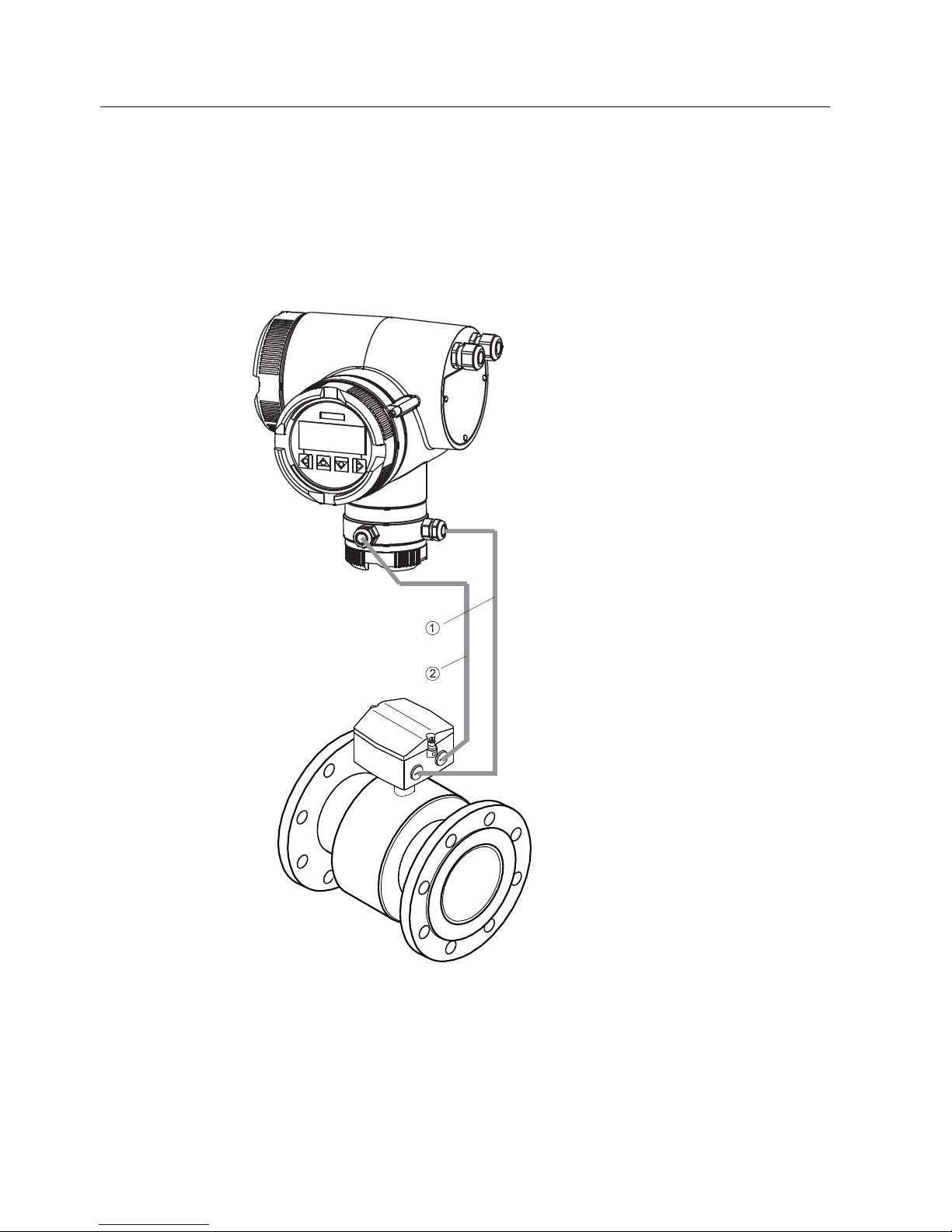
Connecting
The sensor cable shield is connected to the transmitter and sensor as follows:
1. Bend the cable shield back over the clamping piece of the cable gland.
2. Push the clamping piece with the sensor cable into the threaded bush of the cable gland
turning it slightly to the right.
3. Tighten the lock nut on the threaded bushing until the cable is connected tightly (IP67)
① Electrode line
② Magnetic current line
Figure 5-4 Signal transmission from the sensor to the transmitter
 Loading...