

Siemens SITRANS F M MAGFLO series, SITRANS F C MASSFLO series Operating Manual
[]
s
SITRANS F M MAGFLO
®®
®®
®
&
SITRANS F C MASSFLO
®®
®®
®
DeviceNet add-on module
Operating Manual
Order no.: FDK:521H1189
SFIDK.PS.023.C2.02
Technical Documentation (handbooks, instructions, manuals etc.) on the complete product
range SITRANS F can be found on the internet/intranet on the following links:
English:
http://www4.ad.siemens.de/WW/view/en/10806951/133300

DeviceNet add-on module
2
SFIDK.PS.023.C2.02
1. Introduction
Contents
1. Introduction to DeviceNet .......................................................................................... 3
1.1 About this manual ........................................................................................................ 3
1.2 Assumptions ................................................................................................................ 3
1.3 What you should already know ................................................................................... 3
1.4 Product and environment ............................................................................................ 3
1.5 Network ........................................................................................................................ 3
1.6 User profile ................................................................................................................... 3
1.7 Interface to DeviceNet network .................................................................................... 3
2. Technical data ............................................................................................................. 4
3. Installation ................................................................................................................... 5
3.1 Add-on module ............................................................................................................ 5
3.2 Topology ...................................................................................................................... 6
3.3 Cable lengths............................................................................................................... 6
3.4 Cable specifications .................................................................................................... 6
3.6 EMC precautions ......................................................................................................... 7
3.5 Electrical connection.................................................................................................... 7
4. Commissioning ........................................................................................................... 8
4.1 DeviceNet display menu .............................................................................................. 8
4.1.2 Quick set-up ................................................................................................................. 9
4.1.3 Menu item explanation .............................................................................................. 10
4.2. System configuration ................................................................................................. 11
4.3 Polled I/O MAG 6000 .................................................................................................. 11
4.3.1 I/O description ............................................................................................................11
4.3.2 Process data formats ................................................................................................. 12
4.3.3 Status word ................................................................................................................12
4.3.4 Control word .............................................................................................................. 13
4.4. Polled I/O MASS 6000 ............................................................................................... 14
4.4.1 I/O description ............................................................................................................14
4.4.2 Process data formats ................................................................................................. 15
4.4.3 Status word ................................................................................................................15
4.4.4 Control word .............................................................................................................. 16
5. DeviceNet object classes ........................................................................................ 1 7
5.1 Class code 0x01, identity ........................................................................................... 17
5.2 Class code 0x03, DeviceNet ..................................................................................... 17
5.3 Class code 0x04, I/O Assembly ................................................................................. 18
5.4 Class code 0x05, Connection ................................................................................... 19
5.5 Class code 0x65, process data ................................................................................. 19
5.6 Class code 0x66, totalizer ......................................................................................... 20
5.7 Class code 0x67, batch ............................................................................................. 20
5.8 Class code 0x69, system info .................................................................................... 21
5.9 Class code 0x6A, converter ....................................................................................... 21
5.10 Class code 0x6B, sensor ...........................................................................................22
APPENDIX A ........................................................................................................................... 23
SI-Units used in USM II products ...............................................................................23

DeviceNet add-on module
3
SFIDK.PS.023.C2.02
DeviceNet is a distributed control network. The DeviceNet protocol is embedded in the add-on
module (AOM) and is a communication protocol conforming to the Open DeviceNet Vendor
Association (ODVA) standard.
The add-on module allows DeviceNet compatible controllers, sensors and network management
tools to control, monitor and supervise the MAG 6000/MASS 6000 flowmeter. The add-on module
is designed to the DeviceNet system “Protocol for Vendors” as a slave device.
1.4 Product and
environment
The MAG 6000/MASS 6000 flowmeter functions as a slave on the DeviceNet network. All
addressing and linking the nodes is done at installation time by a network manager tool. The
network installer and the network management master have significant influence on how the
nodes function on the network. A DeviceNet network can support up to 64 nodes.
1.5 Network
The end-user is a network manager programmer or controller who sees the DeviceNet add-on
module as an invisble bridge to the flowmeter. Control and supervision of the flowmeter will be
possible through the standard parameter set.
1.6 User profile
The interface connection to the DeviceNet network is implemented through a microprocessor
with an imbedded CAN controller. For the MAG 6000, two different I/O assemblies are available
in the AOM. For the MASS 6000 seven different I/O assemblies are available in the AOM.
The I/O assembly can be controlled by the user. The I/O assembly can only handle polled mode.
For explicit messages the interface uses the pre-configured master functionality.
1.7 Interface to DeviceNet network
This manual is intended to be used both as an instructional and a reference manual. It only
briefly touches on the basics of the DeviceNet protocol.
The manual is also intended to serve as a guideline when you specify and optimize your
communication system.
Even if you are an experienced DeviceNet programmer, we suggest that you read this manual
entirely before you start programming, since important information can be found in all chapters.
1. Introduction to
DeviceNet
1.1 About this manual
This manual assumes that you use a Siemens Flow Instruments MAG 6000 or MASS 6000 unit
with DeviceNet. It also assumes that you are using a PLC or PC, as a master, that is equipped
with a serial communication option supporting all the DeviceNet communication services
required by your application. Furthermore, it is assumed that all requirements stipulated in the
DeviceNet standard as well as those set up in the generic profile and those pertaining to the
MAG 6000 or MASS 6000 flowmeters are strickly observed as well as all limitations mentioned
fully respected.
The Siemens Flow Instruments DeviceNet module is designed to communicate with any master
abiding by the DeviceNet standard. It is therefore assumed that you have full knowledge of the
PC or PLC you intend to use as a master in your system. Any questions pertaining to hardware
or software produced by any other manufacturer is beyond the scope of this manual and is of no
concern to Siemens Flow Instruments.
If you have questions about how to set up master, master communication or communication to
a non Siemens Flow Instruments slave, the appropriate manuals should be consulted.
1.2 Assumptions
1.3 What you should
already know
1. Introduction to DeviceNet

DeviceNet add-on module
4
SFIDK.PS.023.C2.02
2. Technical data
2. Technical data
Functionality:
Process values
Parameter: MAG 6000 MASS 6000
Mass flow
√√
√√
√
Volume flow
√√
√√
√
√√
√√
√
Temperature
√√
√√
√
Density
√√
√√
√
Fraction A
√√
√√
√
Fraction B
√√
√√
√
Pct Fraction A
√√
√√
√
Totalizer 1
√√
√√
√
√√
√√
√
Totalizer 2
√√
√√
√
√√
√√
√
Batch progress
√√
√√
√
√√
√√
√
Totalizer control
Reset
√√
√√
√
√√
√√
√
Hold/Run
√√
√√
√
√√
√√
√
Direction
√√
√√
√
√√
√√
√
Batch control
On/Off
√√
√√
√
√√
√√
√
Setpoint
√√
√√
√
√√
√√
√
Cycle counter
√√
√√
√
√√
√√
√
Cycle counter reset
√√
√√
√
√√
√√
√
Mode: Start
√√
√√
√
√√
√√
√
Pause
√√
√√
√
√√
√√
√
Resume
√√
√√
√
√√
√√
√
Stop
√√
√√
√
√√
√√
√
Maximum batch time
√√
√√
√
√√
√√
√
Batch compensation
√√
√√
√
√√
√√
√
Lead constant
√√
√√
√
Zero adjust
Auto
√√
√√
√
√√
√√
√
Manual
√√
√√
√
√√
√√
√
Zero adjust time
√√
√√
√
Info
Flow direction
√√
√√
√
√√
√√
√
Scale upper
√√
√√
√
√√
√√
√
Scale lower
√√
√√
√
√√
√√
√
Empty pipe limit
√√
√√
√
Calibration factor
√√
√√
√
√√
√√
√
Sensor size
√√
√√
√
√√
√√
√
Active error
√√
√√
√
√√
√√
√
General specifications:
Device type Slave
Baud rates 125, 250, 500 Kbits/s
Max. distance 100-500 meters
Max. number of nodes 64
Supported messaging formats Polling, explicit messaging
Device type Generic device
Certified No
Poll message contents: (depending on configuration)
Production All process values. Batch, zero adjust and error status
Consumption Totalizer and zero adjust control
DeviceNet add-on module
5
SFIDK.PS.023.C2.02
3. Installation
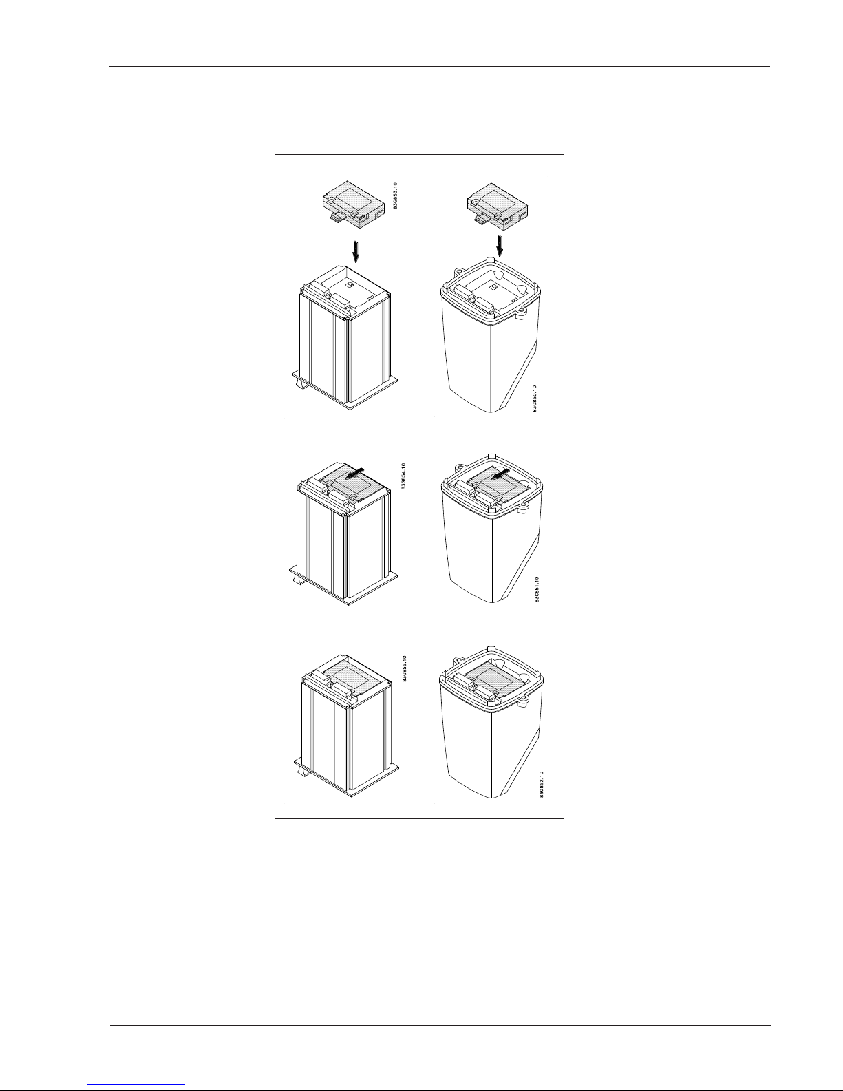
3. Installation
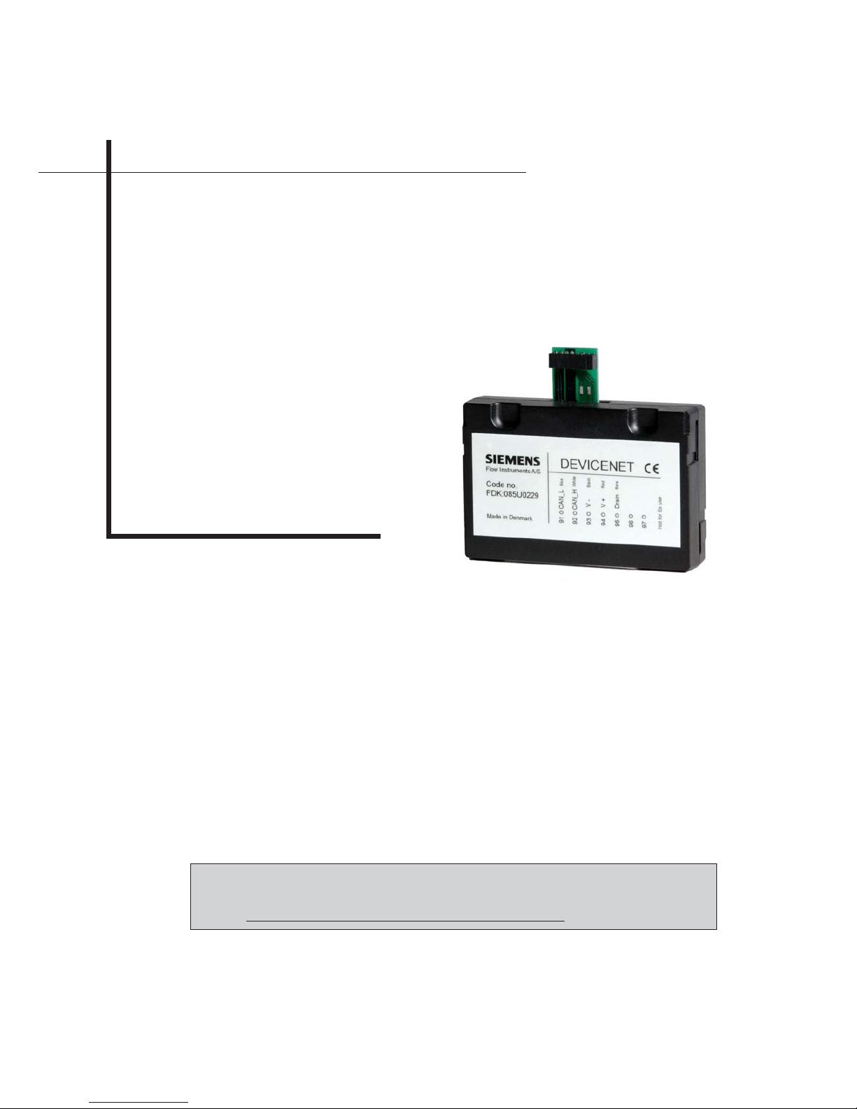
3.1 Add-on module
19” rack mounted versions IP 67 compact versions
The installation procedure for an add-on module to a Siemens Flow Instruments USM II
transmitter is as follows:
1. Unpack the add-on module and
insert it in the bottom of the signal
converter as shown.
2. Press the add-on module in the
direction shown, until it stops and
is firmly seated in position
3. This completes the add-on module installation, and the signal
converter may now be connected
to the terminal box. Communication with the display/keypad and
the electrical input/output terminals is established automatically
when the power is applied.
After mounting, the DeviceNet menus are shown in the display and (set table) values are stored
in the SENSORPROM
®
memory unit
DeviceNet add-on module
6
SFIDK.PS.023.C2.02
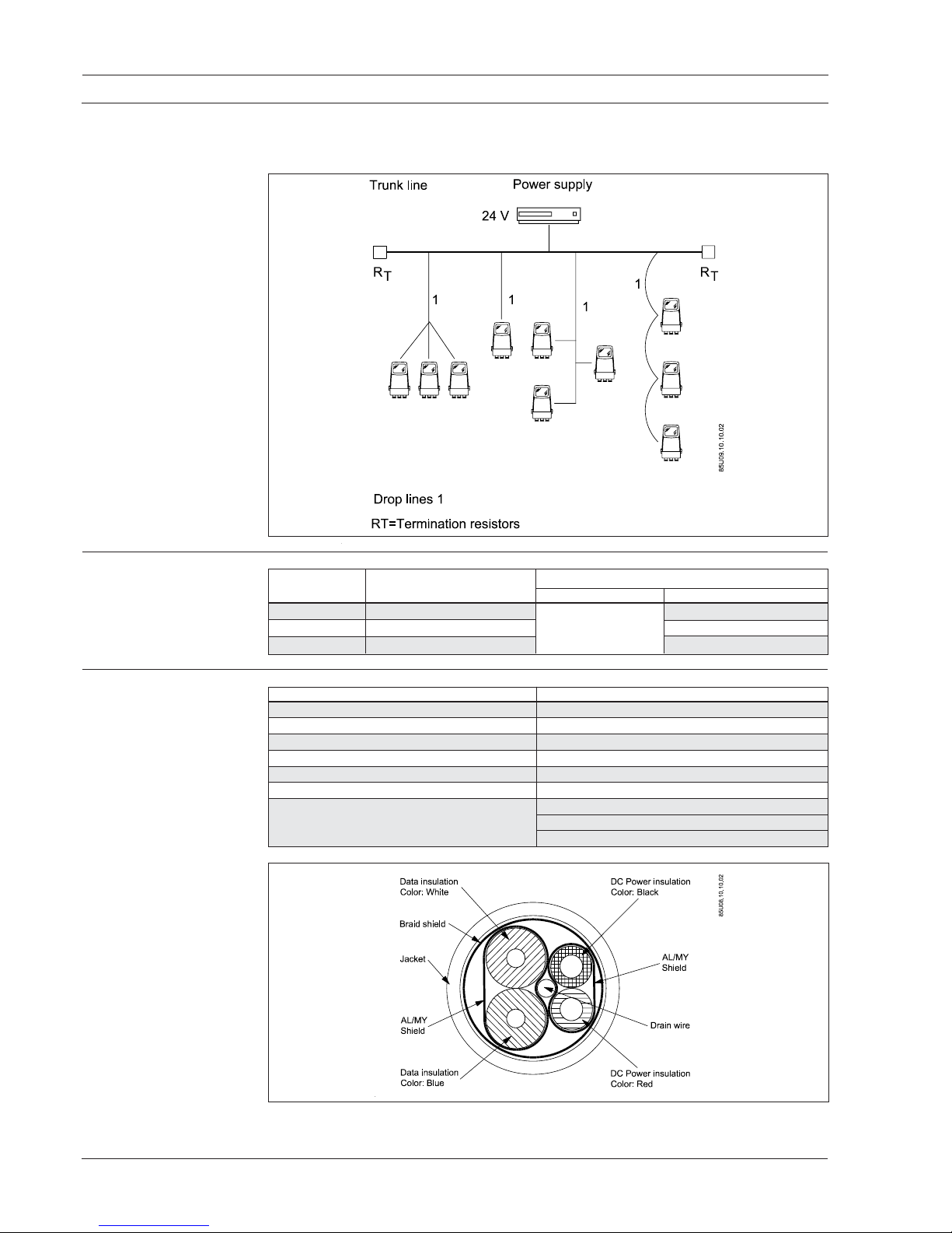
The DeviceNet allows a mixed trunk line/drop line topology. The cable has to be terminated
with a resistor of 121 ohm/0.25W in both ends of the cable.
3.3 Cable lengths
Baud rate Max. total Drop length [m]
cable length [m] Maximum Cumulative
125 K baud 500 meters (1640 ft.) 6 meters (20 ft.) 156 meters (512 ft.)
250 K baud 250 meters (820 ft.) for one drop 78 meters (256 ft.)
500 K baud 100 meters (328 ft.) 39 meters (128 ft.)
3.4 Cable specifications
Electrical characteristics Specifications
Impedance 120 Ohms +/− 10%
Propagation delay 1.36 nSec/ft. (max.)
Cap. between conductors 12 pf/ft. (nominal)
Cap. conductors/shield 24 pf/ft. (nominal)
Cap. unbalance 1200 pf/1000 ft. (max.)
DCR - @20°C 28 Ohms/1000 ft. (max.)
Attenuation 0.29 db/100 ft. @ 125 kHz
0.50 db/100 ft. @ 250 kHz
0.70 db/100 ft. @ 500 kHz
3.2 Topology
3. Installation
DeviceNet add-on module
7
SFIDK.PS.023.C2.02
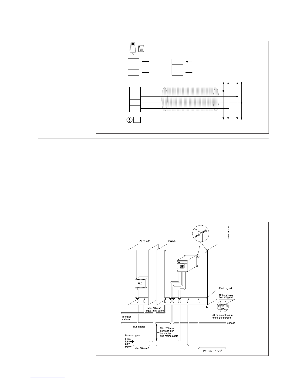
3.5 Electrical connection
3. Installation
3.6 EMC precautions
The following EMC precautions are recommended to obtain an interference free operation of
the Devicenet network. Additional information on EMC can be found in the MAG 6000/MASS
6000 handbooks.
Note
Relevant national and local regulations, for example regarding protective earth connection,
must be observed.
The DeviceNet communication cable must be kept away from cables that can contain electrical
noise such as motor and mains cables to avoid coupling of noise from one cable to the other.
Normally a distance of 200 mm (8 inches) is sufficient, but it is generally recommended to keep
the longest possible distance between the cables, especially where cables are running in
parrallel over long distances.
The use of separate cable trays for signal cables and high power cables has proven to be a very
good practice for eliminating noise coupling.
If the DeviceNet has to cross a main cable or other cables that are a source of noise, they must
cross eachother at an angle of 90°.
PE
Termination: Connecting a resistor of 121Ohm 0.25W over 91,92 will terminate the
DeviceNet Bus. This must be done if the device is the last on the Bus.
CAN_L
CAN_H
V-
V+
Blue
White
Black
Red
92
91
93
94
DeviceNet Cable
11 - 30 V d.c.
11 - 24 V a.c.
Supply voltage
1+
2-
+
−
N
L
N
115 -230 V a.c.
L
Signal converter
Transmitter
DeviceNet add-on module
8
SFIDK.PS.023.C2.02
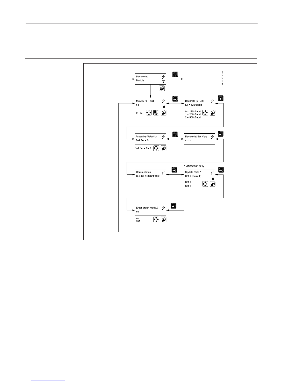
4. Commissioning
4. Commissioning Before communicating with the scanner, the MAC ID, baud rate and assembly selection must
be selected. This can be done either from the local display or from the commissioning software.
Please look in to the transmitter manual to locate the DeviceNet module menu.
4.1 DeviceNet display
menu
 Loading...