

Siemens SITRANS F M MAGFLO MAG 3100 Instructions Manual
s
Introduction
ENGLISH
INSTRUCTIONS
®®
®
SITRANS F M MAGFLO
Electromagnetic flowmeter type MAG 3100 with
®®
DEUTSCH
FRANÇAIS
DANSK
PTFE or PFA liner
®
Siemens Flow Instruments SITRANS F M MAGFLO
sensor and a transmitter. These instructions only describe the sensor installation. For further
information on the transmitter installation, please refer to the SITRANS F M MAGFLO
Technical Documentation (handbooks, instructions, manuals etc.) on the complete product
range SITRANS F can be found on the internet/intranet on the following links:
English: http://www4.ad.siemens.de/WW/view/en/10806951/133300
electromagnetic flowmeters consist of a
®
handbook.
A5E01019391
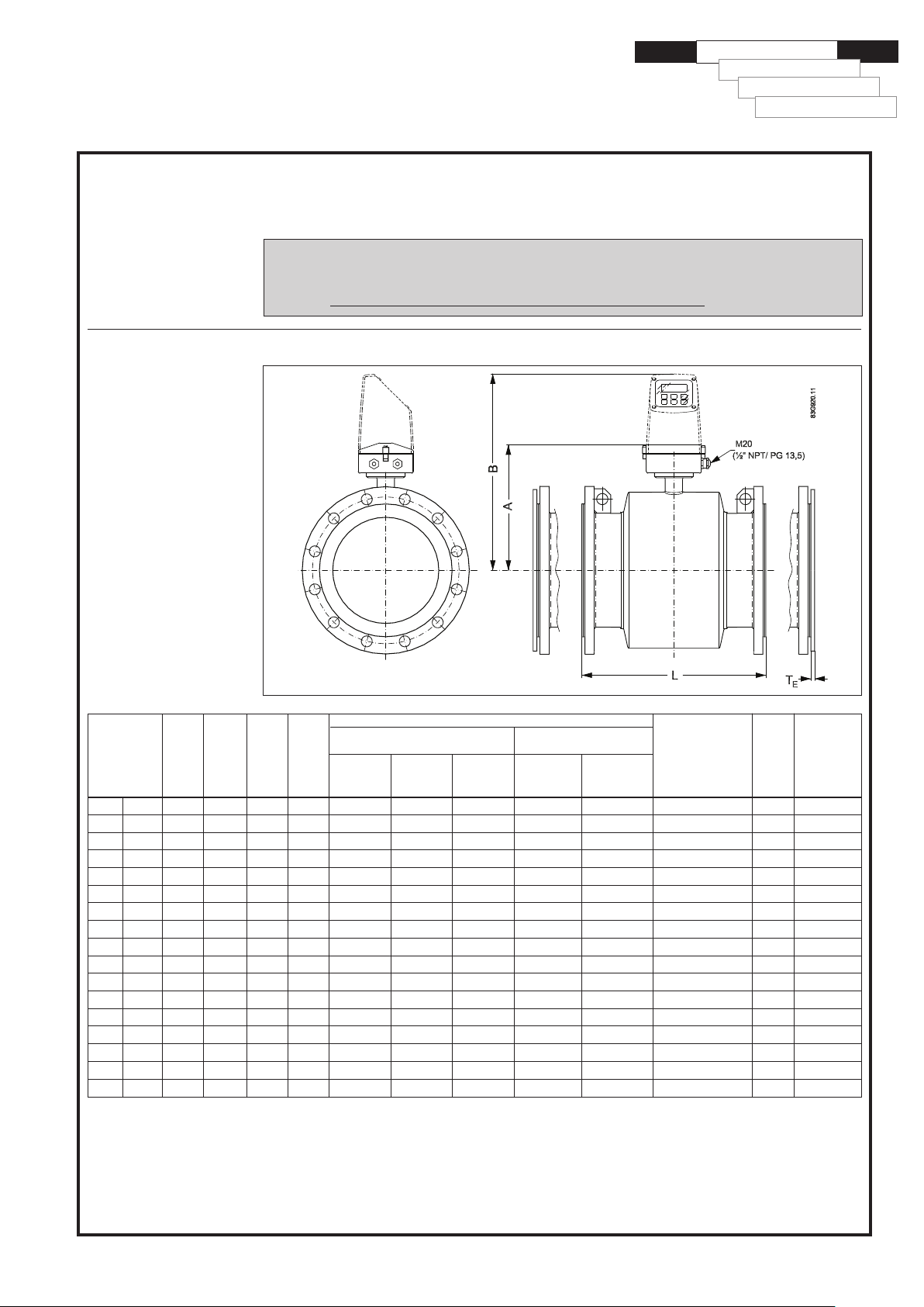
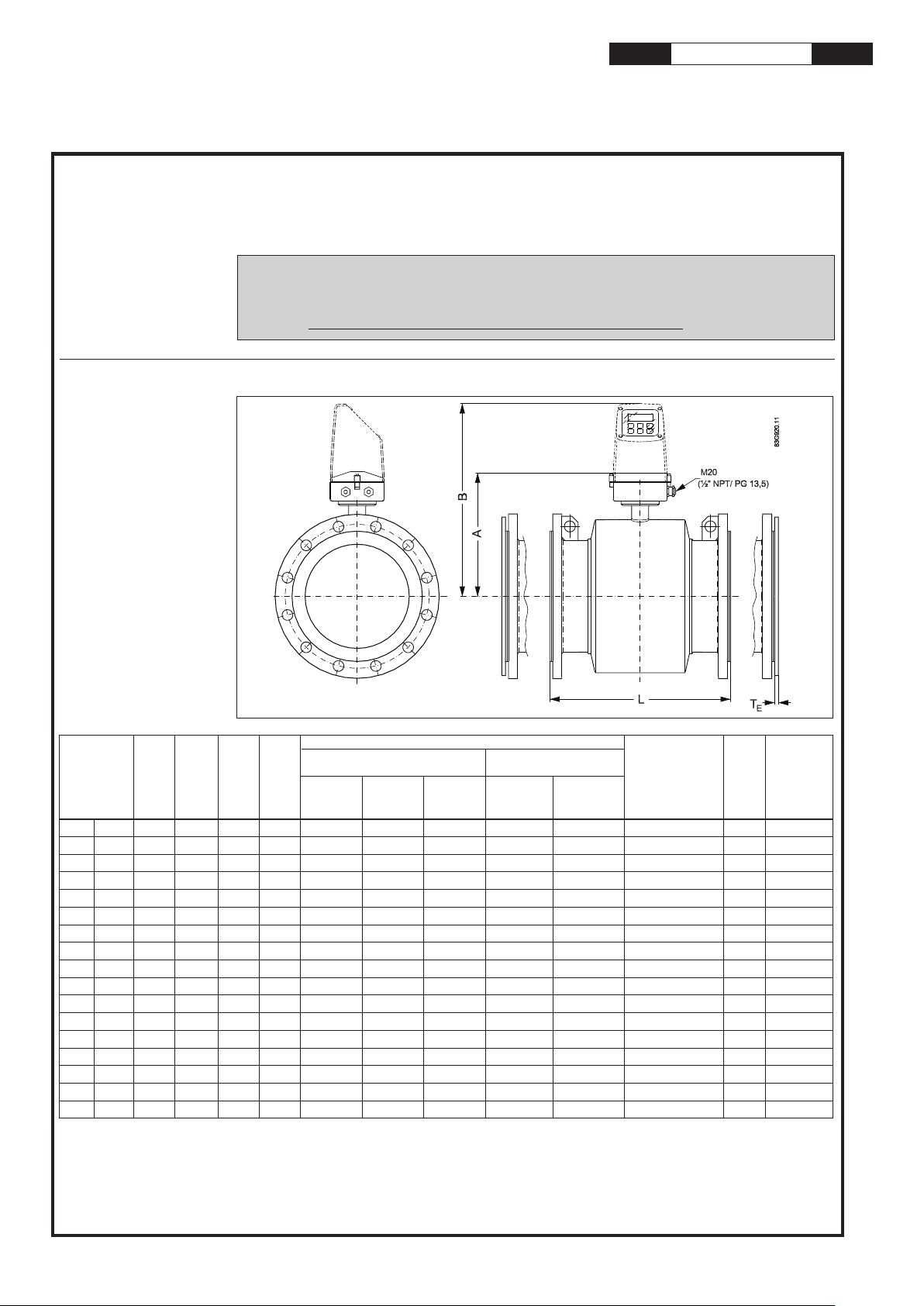
Dimensions and
MAG 3100 with PTFE or PFA liner
weight
Nominal
size
[mm] [inch] [mm] [mm] [mm] [mm] [mm] [mm] [mm] [mm] [mm] [mm] [mm] [kg]
15 ½ 187 338 59 104 - - 200 200 200 200 6 4
25 1 187 338 59 104 - - 200 200 200 200 6 5
40 1½ 197 348 82 124 - - 200 200 200 200 6 8
50 2 205 356 72 139 - - 200 200 200 200 6 9
65 2½ 212 363 72 154 200 - 200 200 272 200 6 11
80 3 222 373 72 174 200 - 272 272 272 200
100 4 242 393 85 214 250 - 250 250 310 250 6 16
125 5 255 406 85 239 250 - 250 250 335 250 6 19
150 6 276 427 85 282 300 - 300 300 300 300 6 27
200 8 304 455 137 338 350 350 350 350 350 350 8 40
250 10 332 483 157 393 450 450 450 450 450 450 8 60
300 12 357 508 157 444 500 500 500 500 500 500 8 80
350 14 362 513 270 451 550 550 550 550 550 550 8 110
400 16 387 538 270 502 600 600 600 600 600 600 10 125
450 18 418 569 310 563 600 600 600 600 600 600 10 175
500 20 443 594 350 614 600 625 680 600 730 600
600 24 494 645 430 715 600 750 800 600 860 600
1
) When earthing flanges are used, the thickness of the earthing flange must be added to the built-in length
2
)TE = Type E grounding ring for PTFE only
3
) Weights are approx. and for PN 16 without transmitter
4
) PN 35 DN 500 = 680 mm
5
) PN 35 DN 600 = 750 mm
6
) PN 35 DN 80 = 272 mm
- Not available, D = Outside diameter of flange, see flange tables
A A1BD
1
EN 1092-1-2001
PN PN PN Class Class Class 21 (PN 21)
6, 10, 16 25 40 150 300 Class 35 (PN 35)
1)
L
BS 1560/ANSI 16.5
AS 2129 E T
AS 4087
Class 14 (PN 16)
6)
4)
5)
2)
Weight
E
612
10 200
10 287
3)
SFIDK.PI.024.E4.52
SITRANS F M MAGFLO
®®
®
®®
Electromagnetic flowmeter type MAG 3100 with PTFE or PFA liner
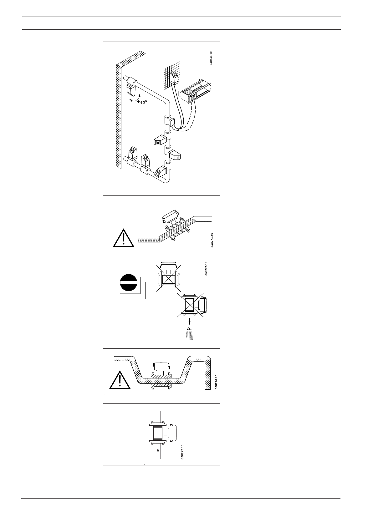
Installation, general
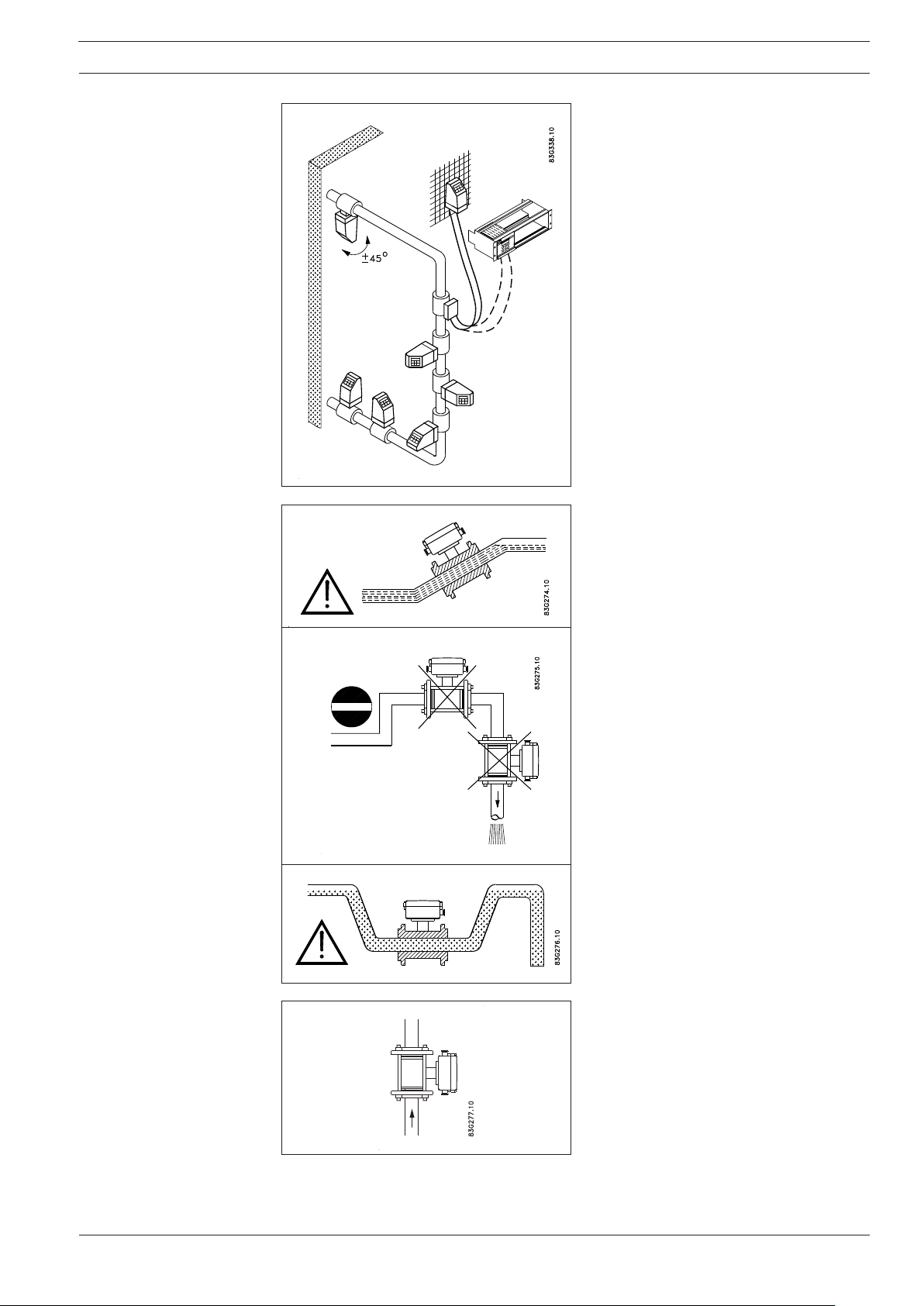
Reading and operating the flowmeter is possible under almost any installation conditions because the display can be oriented in
relation to the sensor. To ensure optimum
flow measurement attention should be paid
to the following:
The sensor must always be completely full
with liquid.
Therefore avoid:
• Installation at the highest point in the pipe
system.
• Installation in vertical pipes with free outlet.
For partially filled pipes or pipes with downward flow and free outlet the flowmeter should
be located in a U-tube.
Installation in vertical pipes
Recommended flow direction: upwards. This
minimizes the effect on the measurement of
any gas/air bubbles in the liquid.
2
SITRANS F M MAGFLO
®®
®
®®
Electromagnetic flowmeter type MAG 3100 with PTFE or PFA liner
Installation, general
(continued)
Installation in horizontal pipes
The sensor must be mounted as shown in
the upper figure. Do not mount the sensor as
shown in the lower figure. This will position
the electrodes at the top where there is
possibility for air bubbles and at the bottom
where there is possibility for mud, sludge,
sand etc.
If using empty pipe detection, the sensor can
be tilted 45° , as shown in the upper figure.
Measuring abrasive liquids and liquids
containing particles
Recommended installation is in a vertical/
inclined pipe to minimize the wear and deposits in the sensor.
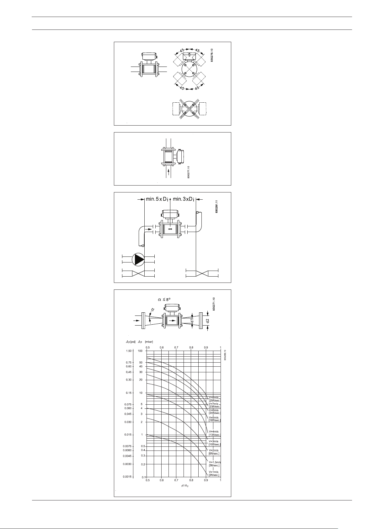
Inlet and outlet conditions
To achieve accurate flow measurement it is
essential to have straight lengths of inlet and
outlet pipes and a certain distance between
pumps and valves.
It is also important to centre the flowmeter in
relation to pipe flanges and gaskets.
Pressure drop
The flowmeter can be installed between two
reducers (e.g. DIN 28545). At 8° the following pressure drop curve applies. The curves
are applicable to water.
Example:
A flow velocity of 3 m/s (V) in a sensor with a
diameter reduction from DN 100 to DN 80
= 0.8) gives a pressure drop of 2.9
(d
1/d2
mbar.
3
SITRANS F M MAGFLO
®®
®
®®
Electromagnetic flowmeter type MAG 3100 with PTFE or PFA liner
Installation, general
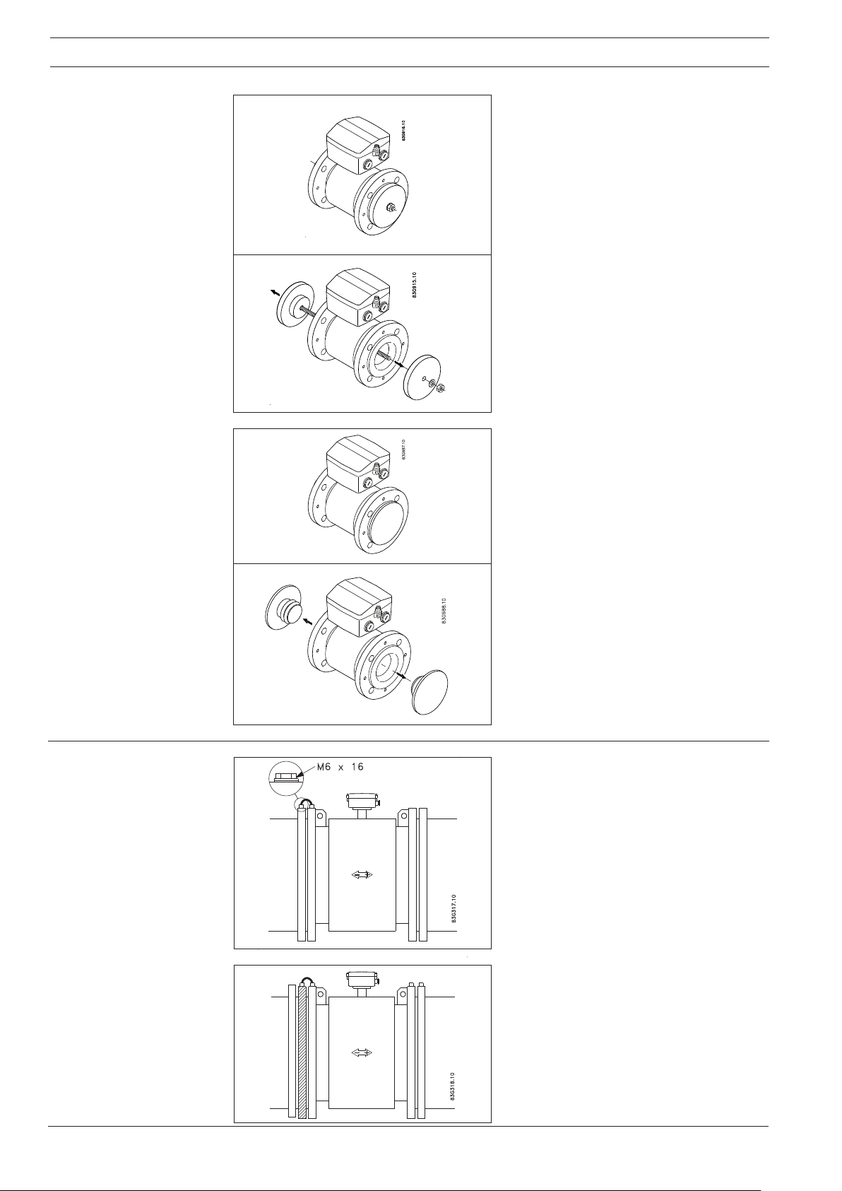
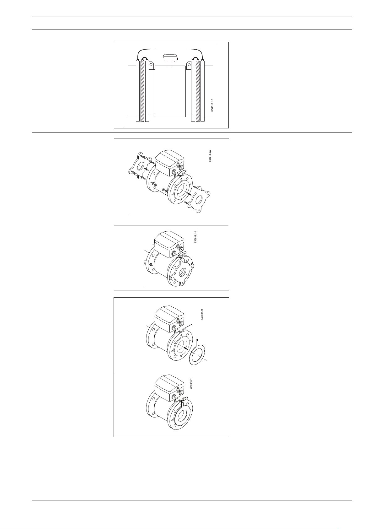
For PTFE liner
For PFA liner
The sensor is equipped with a liner of PTFE
teflon. At delivery the sensor is mounted with
wooden blanks to hold the liner in place during
transportation and storage. These blanks
should remain on the sensor until installation.
Without the blanks the liner will creep back
towards its original shape and installation will
be more difficult to carry out.
The sensor should max. be left a few hours
without the blanks.
Immediately before installation, remove the
blanks.
The sensor is equipped with a liner of PFA. At
delivery the sensor is mounted with blanks to
protect the liner during transportation and
storage. These blanks should remain on the
sensor until installation.
Potential equalization
Before installation, remove the blanks without
using sharp objects which can damage the
liner.
Electrically conductive piping
Potential equalization with an electrically conductive pipe.
Use an earth straps on one side.
Non-conductive piping
Here an earthing flange is used, placed between flowmeter and the adjacent pipe flange.
Earthing flange type E for PTFE.
For PFA flat rings must be used.
4
SITRANS F M MAGFLO
®®
®
®®
Electromagnetic flowmeter type MAG 3100 with PTFE or PFA liner
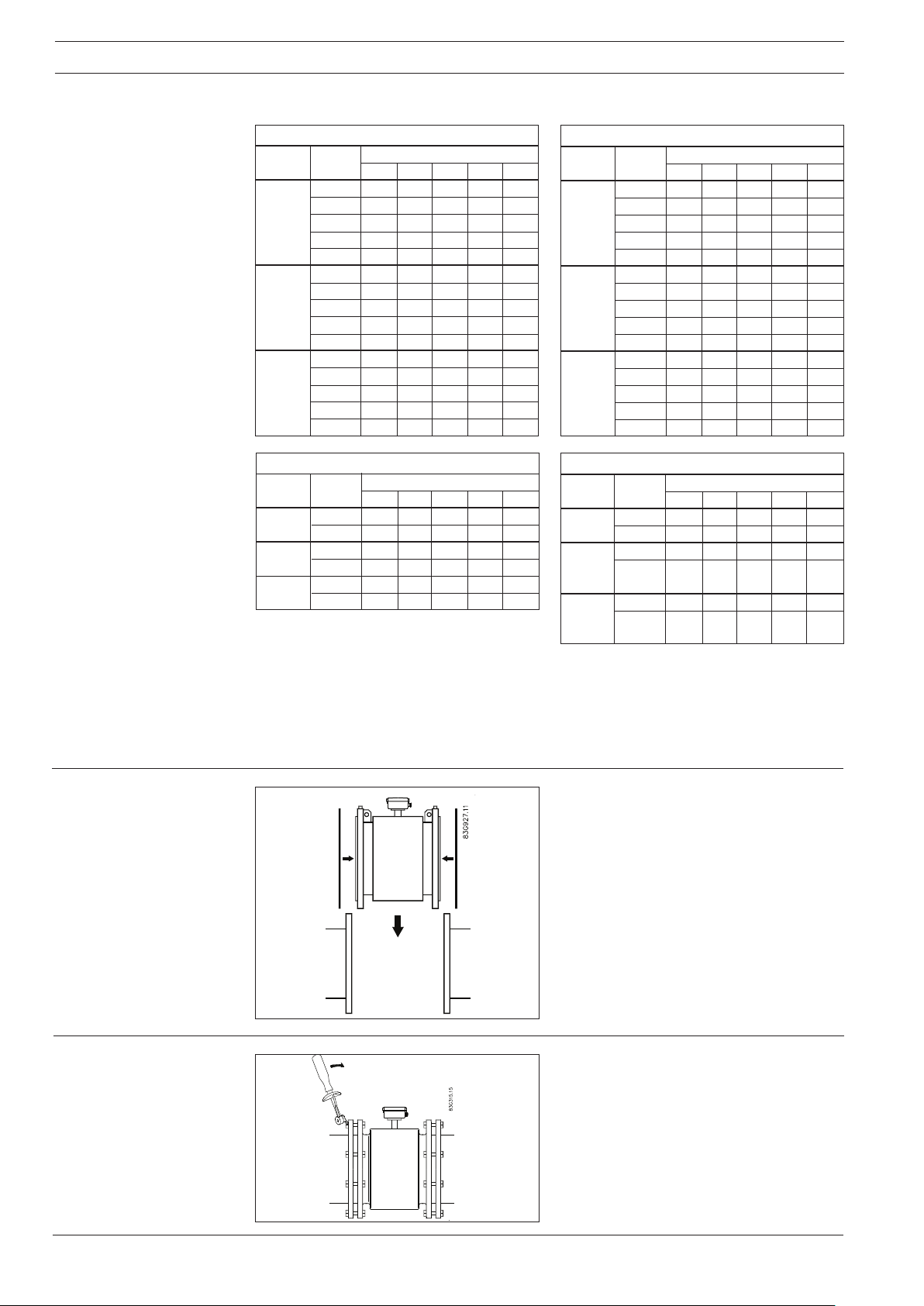
Cathodic protected piping
Earting flanges
For PTFE liner
Special attention must be given to systems
with cathodic protection.
By compact mounting:
The transmitter must be supplied through an
isolation transformer. The terminal "PE" must
never be connected.
By remote mounting:
The screen must only be connected at the
sensor end via a 1.5 μF condensator. The
screen must never be connected at both ends.
By isolated sensor:
If above mentioned connections are unacceptable, the sensor must be isolated from the
pipe work.
Where necessary on non conductive pipes,
mount earthing flanges type E.
For potential equalization one earthing flange
is sufficient even for bidirectional flow. With
unidirectional flow the earthing flange should
be mounted on the inlet side.
In special cases with abrasive flow the earthing
flanges will also work as inlet protection.
High temperature sensors are delivered with
two factory mounted earthing flanges. No further action need to be taken for potential equalisation.
For PFA liner
Earthing flanges must be connected to the
meter body with the enclosed earthing straps.
Where necessary on non conductive pipes,
mount flat earthing rings.
For potential equalization one earthing ring is
sufficient even for bidirectional flow. With unidirectional flow the earthing ring should be
mounted on the inlet side.
In special cases with abrasive flow the earthing
ring will also work as inlet protection.
Earthing rings must be connected to the meter
body with the enclosed earthing straps.
5
SITRANS F M MAGFLO
®®
®
®®
Electromagnetic flowmeter type MAG 3100 with PTFE or PFA liner
Effect of temperature and
material on working
pressure
Metric (Pressures in bar)
PN rated flanges
Material Flange Temperature
group rating −20 50 100 150 180
1C1 PN 6 6.0 6.0 6.0 5.8 5.6
(A105) PN10 10.0 10.0 10.0 9.7 9.4
PN16 16.0 16.0 16.0 15.6 15.1
PN 25 25.0 25.0 25.0 24.4 23.7
PN 40 40.0 40.0 40.0 39.1 37.9
2C1 PN 6 5.5 5.3 4.5 4.1 3.8
(304) PN 10 9.1 8.8 7.5 6.8 6.3
PN 16 14.7 14.2 12.1 11.0 10.2
PN 25 23.0 22.1 18.9 17.2 16.0
PN 40 36.8 35.4 30.3 27.5 25.5
2C2 PN 6 5.5 5.3 4.6 4.2 3.9
(316) PN 10 9.1 8.9 7.8 7.1 6.6
PN 16 14.7 14.3 12.5 11.4 10.6
PN 25 23.0 22.3 19.5 17.8 16.5
PN 40 36.8 35.6 31.3 28.5 26.4
ANSI flanges
Material Flange Temperature
group rating −20 38 93 149 180
1.1 Cl. 150 19.7 19.7 17.9 15.9 14.7
(A105) Cl. 300 51.0 51.0 46.6 45.2 44.4
2.1 Cl. 150 19.0 19.0 15.9 14.1 13.6
(F304) Cl. 300 49.7 49.7 41.4 37.2 35.5
2.2 Cl. 150 19.0 19.0 16.2 14.8 14.1
(F316) Cl. 300 49.7 49.7 42.8 38.6 36.9
°°
° C
°°
°°
° C
°°
Imperial (Pressures in Psi)
PN rated flanges
Material Flange Temperature
group rating −5 122 212 302 356
ASTM PN 6 87 87 87 84 81
A105 PN 10 145 145 145 141 136
PN 16 232 232 232 226 219
PN 25 363 363 363 354 344
PN 40 580 580 580 567 550
ASTM PN 6 80 77 65 59 55
A240 PN 10 132 128 109 99 91
304 PN 16 213 206 175 160 148
PN 25 334 320 274 249 232
PN 40 534 513 439 399 370
ASTM PN 6 80 77 67 61 57
A240 PN 10 132 129 113 103 96
316 PN 16 213 207 181 165 154
PN 25 334 323 283 258 239
PN 40 534 516 454 413 383
ANSI flanges
Material Flange Temperature
group rating −5 100 200 300 356
ASTM Cl. 150 285 285 260 230 213
A105 Cl. 300 740 740 675 655 644
ASTM Cl. 150 275 275 230 205 197
A240 Cl. 300 720 720 600 540 515
F304
ASTM Cl. 150 275 275 235 215 204
A240 Cl. 300 720 720 620 560 535
F316
°°
° F
°°
°°
° F
°°
The above tables show the effect that an increase of temperature or change of material have
on the maximum working pressure of the flange. The values are independent of nominal size.
For intermediate temperatures use value from nearest higher temperature.
Example
For a PN 16 flange in 2C2 (316) material at 80 degrees the maximum working pressure should
be taken as 12.5 bar.
Installation
Tightening
The sensor must be mounted between two
flanges. Gaskets are only necessary when the
flowmeter is installed with earthing flanges as
the liner replaces gaskets.
Standard bolts must be well lubricated and
tightened evenly around the gasket. Leakage/
damage to the flowmeter or piping may arise if
bolts are overtightened.
6
®®
®
SITRANS F M MAGFLO
®®
Electromagnetic flowmeter type MAG 3100 with PTFE or PFA liner
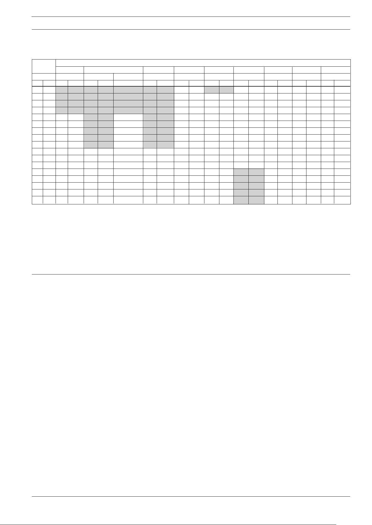
Maximum allowable torques
(to meet PED)
Nominal Maximum torque
size EN 1092-1 EN 1092-1 EN 1092-1 EN 1092-1 EN 1092-1 ANSI B16.5 ANSI B16.5 AS 2129 JIS JIS
PN 6 PN 10 PN 16 PN 25 PN 40 Class 150 Class 300 Table E K10 K20
mm Inch Nm F/Lbs Nm F/Lbs Nm F/Lbs Nm F/Lbs Nm F/Lbs Nm F/Lbs Nm F/Lbs Nm F/Lbs Nm F/Lbs Nm F/Lbs
15½”N/AN/AN/AN/AN/AN/AN/AN/A107N/AN/A32648686
251"N/AN/AN/AN/AN/AN/AN/AN/A161275 759716121612
40 1½” N/A N/A N/A N/A N/A N/A N/A N/A 34 25 9 7 18 13 17 13 20 15 20 15
50 2" N/A N/A N/A N/A N/A N/A N/A N/A 46 34 20 14 11 8 20 15 27 20 13 10
65 2½” 10 7 N/A N/A 25 18 N/A N/A 34 25 25 18 16 12 21 16 36 27 18 13
80 3" 25 18 N/A N/A 25 18 N/A N/A 42 31 34 25 24 18 32 23 21 16 28 21
100 4" 25 18 N/A N/A 25 18 N/A N/A 72 53 26 19 34 25 24 18 26 19 37 27
125 5" 25 18 N/A N/A 32 24 N/A N/A 114 84 42 31 42 31 33 24 43 32 59 44
150 6" 25 18 N/A N/A 50 37 N/A N/A 144 106 57 42 35 26 40 30 76 56 40 30
200 8" 25 18 50 37 52 38 105 77 185 137 88 65 57 42 61 45 46 34 62 45
250 10" 25 18 50 37 88 65 160 118 300 221 99 73 57 42 62 46 72 53 113 83
300 12" 50 37 60 44 117 86 170 125 320 236 132 97 86 63 78 58 56 41 96 71
350 14" 50 37 60 44 120 89 240 177 450 332 225 166 N/A N/A 147 109 72 53 147 108
400 16" 50 37 88 65 170 125 330 244 650 480 210 155 N/A N/A 168 124 115 85 175 129
450 18" 56 41 92 68 170 125 320 236 570 421 220 162 N/A N/A 164 121 109 80 184 135
500 20" 53 39 103 76 230 170 390 288 740 546 200 148 N/A N/A 194 143 127 93 211 155
600 24" 81 60 161 119 350 258 560 413 1220 900 280 207 N/A N/A 306 225 150 111 255 188
Torque calculations
Manufacturer’s design
and safety statement
All values are theoretical and are calculated making the following assumptions:
1. All bolts are new and material selection is according to EN 1515-1 table 2.
2. The standard flange gasket material to be used between the flowmeter and mating flanges
should not exceed 75 shore A durometer.
3. All bolts are galvanized and adequately lubricated.
4. The values are calculated for use with carbon steel flanges.
5. Flowmeter and mating flanges are correctly aligned.
1. Responsibility for the choice of lining and electrode materials with regard to their abrasion
and corrosion resistance lies with the purchaser; the effect of any change in process
medium during the operating life of the flowmeter should be taken into account. Incorrect
selection
of lining and/or electrode materials could lead to a failure of the flowmeter.
2. It is the responsibility of the user to ensure that stresses and loading caused by earthquakes,
traffic, high winds and fire damage are taken into account during installation, when
appropriate. These forces are not taken into account during flowmeter design.
3. It is the responsibility of the user to ensure that the flowmeter is installed such that it does
not act as a focus for pipeline stresses. External loadings are not taken into account during
flowmeter design.
4. During operation do not exceed the pressure and/or temperature ratings indicated on the
data label or in the installation instructions.
5. It is the responsibility of the user to ensure that all installations include over pressure
protection, means for draining/venting, and that adequate protection is provided to
minimise any risk of contact with hot surfaces.
6. Under the Pressure Equipment Directive this product is a pressure accessory, and not
approved for use as a safety accessory, as defined by the Pressure Equipment Directive.
emoval of the terminal box except by Siemens Flow Instruments or their approved agents
7. R
will invalidate the PED conformity of the product.
In accordance with the Pressure Equipment Directive (97/23/EC)
7
s
INSTRUCTIONS
DEUTSCH
®®
®
SITRANS F M MAGFLO
Magnetisch induktiver Durchflussmesser Typ MAG 3100 mit
PTFE- oder PFA- Auskleidung
®®
Einführung
Abmessungen und
Gewichte
Siemens Flow Instruments SITRANS F M MAGFLO
®
magnetisch-induktive Durchflussmesser
bestehen aus einem Messaufnehmer und einem Messumformer. Diese Instruktion beschreibt nur
die Montage des Messaufnehmers. Für weitere Informationen über die Montage des Messumformers,
siehe bitte das SITRANS F M MAGFLO
®
Produkthandbuch.
Technische Unterlagen (Handbücher, Instruktionen, Betriebsanleitung usw.) des
kompletten Warenangebotes von SITRANS F sind auf dem Internet/Intranet unter folgenden
Links verfügbar
Deutsch:
http://www4.ad.siemens.de/WW/view/de/10806951/133300
MAG 3100 mit PTFE- oder PFA-Auskleidung
A5E01019391
Nominelle
Nennweite
[mm] [inch] [mm] [mm] [mm] [mm] [mm] [mm] [mm] [mm] [mm] [mm] [mm] [kg]
15 ½ 187 338 59 104 - - 200 200 200 200 6 4
25 1 187 338 59 104 - - 200 200 200 200 6 5
40 1½ 197 348 82 124 - - 200 200 200 200 6 8
50 2 205 356 72 139 - - 200 200 200 200 6 9
65 2½ 212 363 72 154 200 - 200 200 272 200 6 11
80 3 222 373 72 174 200 - 272 272 272 2006)612
100 4 242 393 85 214 250 - 250 250 310 250 6 16
125 5 255 406 85 239 250 - 250 250 335 250 6 19
150 6 276 427 85 282 300 - 300 300 300 300 6 27
200 8 304 455 137 338 350 350 350 350 350 350 8 40
250 10 332 483 157 393 450 450 450 450 450 450 8 60
300 12 357 508 157 444 500 500 500 500 500 500 8 80
350 14 362 513 270 451 550 550 550 550 550 550 8 110
400 16 387 538 270 502 600 600 600 600 600 600 10 125
450 18 418 569 310 563 600 600 600 600 600 600 10 175
500 20 443 594 350 614 600 625 680 600 730 6004) 10 200
600 24 494 645 430 715 600 750 800 600 860 6005) 10 287
1
) Beim Ensatz von Erdungsflanschen muss die Wandstärke zur Gesamtlänge hinzugerechnet werden
2
)TE = Typ E Erdungsflansch
3
) Die Gewichtsangaben sind Näherungswerte und gelten für PN 16 Flanschausführungen ohne Messumformer
4
) PN 35 DN 500 = 680 mm
5
) PN 35 DN 600 = 750 mm
6
) PN 35 DN 80 = 272 mm
- Nicht verfügbar, D = Außendurchmesser des Flansches
A A1BD
1
EN 1092-1-2001
PN PN PN Class Class Class 21 (PN 21)
6, 10, 16 25 40 150 300 Class 35 (PN 35)
1)
L
BS 1560/ANSI 16.5
AS 2129 E T
AS 4087
Class 14 (PN 16)
E
2)
Gewicht
3)
SFIDK.PI.024.E4.52
SITRANS F M MAGFLO
®®
®
®®
Magnetisch induktiver Durchflussmesser Typ PTFE- oder PFA-Auskleidung
Einbau, allgemein
Der Durchflussmesser kann in jeder Einbaulage abgelesen werden, da die Anzeige
drehbar ist und in jeder beliebigen Position
im Verhältnis zum Messaufnehmer eingebaut werden kann. Die endgültige Position
sollte vor der Montage festgelegt werden.
Um optimale Messergebnisse zu sichern,
sind folgende Hinweise zu beachten:
Der Messaufnehmer muss immer vollständig gefüllt sein.
Vermeiden Sie:
• Einbau an höchster Stelle des Rohrsystems
• Einbau in einer senkrechten Rohrleitung
mit freiem Ablauf.
Ist eine nur teilweise gefüllte Rohrleitung
oder der freie Ablauf nicht zu vermeiden,
sollte der Durchflussmesser gedükert werden.
Einbau in einer senkrechten Rohrleitung
Empfohlene Strömungsrichtung: von unten
nach oben. Dadurch werden ungenaue
Messergebnisse, verursacht durch Gas- bzw.
Luftblasen im Medium, vermieden.
9
 Loading...