

Siemens SITRANS F M MAGFLO Operating Manual

Order no.: FDK:521H1184
SFIDK.PS.026.C2.02
SITRANS F M MA GFLO
®®
®®
®
Electromagnetic flowmeters
Transmitter type MAG 6000 19" &
safety barrier [EEx ia/ib] IIB
sensor type MAG 1100 Ex & MAG 3100 Ex
[]
*083R9171*
Operating Manual
s

SITRAN S F M MAGFLO
®®
®®
®
2
SFIDK.PS.026.C2.02
ENGLISH
Contents
1. Introduction...................................................................................................................... 3
2. Installation ....................................................................................................................... 4
2.1 Installation of transmitter MAG 6000 ............................................................................... 4
2.2 Installation of sensor .......................................................................................................4
2.3.1 Remote installation - At the sensor ................................................................................. 6
2.3.2 Remote installation - Transmitter in 19" inser t ................................................................ 6
2.4 Ex survey according to Directive 94/9/EC (ATEX) .......................................................... 7
2.5 Overview and intrinsically safe data ............................................................................... 8
2.6 Device identification........................................................................................................8
2.7 Approvals ........................................................................................................................ 9
2.8 Special conditions for safe use ..................................................................................... 10
3. Electrical connection .....................................................................................................11
3.1.1 19” IP 20 version EEx (ia/ib) DN ≤ 300 ......................................................................... 11
3.1.2 19” IP 20 version EEx e (ib) DN ≥ 350 .......................................................................... 11
3.1.3 19” IP 66 version EEx (ia/ib) DN ≤ 300 ......................................................................... 11
3.1.4 19” IP 66 version EEx e (ib) DN ≥ 350 .......................................................................... 11
3.2 Transmitter MAG 6000.................................................................................................. 1 2
4. Technical data ............................................................................................................... 13
4.1.1 Dimensions and weight MAG 1100 Ex ......................................................................... 13
4.1.2 Sensor MAG 1100 Ex .................................................................................................... 1 4
4.2.1 Dimensions and weight MAG 3100 Ex ......................................................................... 15
4.2.2 Sensor MAG 3100 Ex .................................................................................................... 1 6
4.3 Transmitter MAG 6000 .................................................................................................. 1 7
4.4.1 Safety barrier (ia/ib) DN ≤ 300 ...................................................................................... 1 8
4.4.2 Safety barrier (ia) DN ≥ 350 .......................................................................................... 18
4.4.3 IS data sensor ............................................................................................................... 18
4.5 Output characteristics MAG 6000 ................................................................................. 19
5. Commissioning ............................................................................................................. 20
5.1 Keypad and display layout ............................................................................................ 20
5.2.1 Basic settings ................................................................................................................21
5.2.2 Outputs ..........................................................................................................................22
5.2.3 External input ................................................................................................................ 22
5.2.4 Sensor characteristics................................................................................................... 23
5.2.5 Language mode ............................................................................................................ 23
5.2.6 Service mode ................................................................................................................ 24
6. Service .......................................................................................................................... 25
6.1 Transmitter check list..................................................................................................... 25
6.2 Trouble shooting MAG transmitter ................................................................................ 2 6
7. Ordering ........................................................................................................................ 27
8. Certificates .................................................................................................................... 28
8.1 EC-declaration of conformity ......................................................................................... 28
8.2 EC type examination certificate .................................................................................... 29

SITRAN S F M MAGFLO
®®
®®
®
3
SFIDK.PS.026.C2.02
ENGLISH
1. Introduction
For safety reasons it is important that the following points, especially the points marked with
a warning sign, are read and understood before the system is being installed:
• Installation, connection, commissioning and service must be carried out by personnel
who are qualified and authorized to do so.
• It is very important that the same people have read and understand the instructions and
directions provided in this manual and that they follow the instructions and directions
before taking the equipment into use!
• People who are authorized and trained by the owner of the equipment may operate the
equipment.
• The installation must ensure that the measuring system is correctly connected and is
in accordance with the connection diagram. The transmitter has to be earthed unless
the power supply is galvanically isolated.
• In applications with working pressures/media that can be dangerous to people,
surroundings, equipment or others in case of pipe fracture, we recommend that special
precautions such as special placement, shielding or installation of a security guard or
a security valve should be made when the sensor is being installed.
• Siemens Flow Instruments want to assist by estimating the chemical resistance of the
sensor parts that are in connection with the media, but it is at any time the customer’s
responsibility, which materials are chosen and Siemens Flow Instruments takes no
responsibility if the sensor corrodes!
• Equipment used in hazardous areas must be Ex-approved and marked for Europe
and UL for USA.
It is required that the special directions provided in the manual and in the Ex certificate
must be followed!
• Installation of the equipment must comply with national regulations.
Example EN 60079-14 for Denmark.
• Repair and service can be done by approved Siemens Flow Instruments personnel
only.
1. Introduction
SITRAN S F M MAGFLO
®®
®®
®
4
SFIDK.PS.026.C2.02
ENGLISH
2. Installation
2. Installation
Category 2 equipment
Sensors may be installed in zone 1 and zone 2.
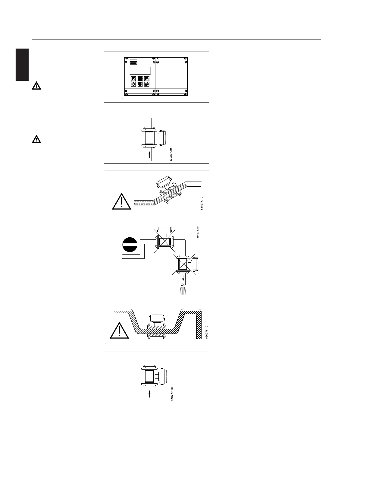
2.2 Installation of sensor
Transmitter MAG 6000 can be installed in the
safe area only!
2.1 Installation of
transmitter MAG
6000
Safe area only!
Hazardous area
The sensor must always be completely full with
liquid.
Therefore avoid:
• Installation at the highest point in the pipe
system
• Installation in vertical pipes with free outlet
For partially filled pipes or pipes with downward flow and free outlet the flowmeter should
be located in a U-tube.
Installation in vertical pipes
Recommended flow direction: upwards. This
minimizes the effect on the measurement of
any gas/air bubbles in the liquid.
SITRAN S F M MAGFLO
®®
®®
®
5
SFIDK.PS.026.C2.02
ENGLISH
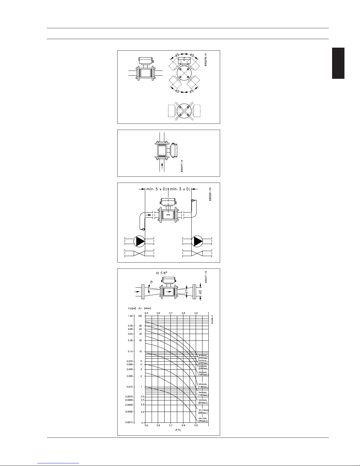
Installation in horizontal pipes
The sensor must be mounted as shown in the
upper figure. Do not mount the sensor as shown
in the lower figure. This will position the electrodes at the top where there is possibility for air
bubbles and at the bottom where there is possibility for mud, sludge, sand etc.
If using empty pipe detection the sensor can be
tilted 45°, as shown in the upper figure.
Measuring abrasive liquids and liquids containing particles
Recommended installation is in a vertical/inclined pipe to minimize the wear and deposits
in the sensor.
Inlet and outlet conditions
To achieve accurate flow measurement it is
essential to have straight lengths of inlet and
outlet pipes and a certain distance between
pumps and valves.
It is also important to centre the flowmeter in
relation to pipe flanges and gaskets.
2.2 Installation of sensor
(continued)
Installation in large pipes
The flowmeter can be installed between two
reducers (e.g. DIN 28545). Assuming that at 8°
the following pressure drop curve applies. The
curves are applicable to water.
Example:
A flow velocity of 3 m/s (V) in a sensor with a
diameter reduction from DN 100 to DN 80
(d
1/d2
= 0.8) gives a pressure drop of 2.9 mbar.
2. Installation
SITRAN S F M MAGFLO
®®
®®
®
6
SFIDK.PS.026.C2.02
ENGLISH
2. Installation
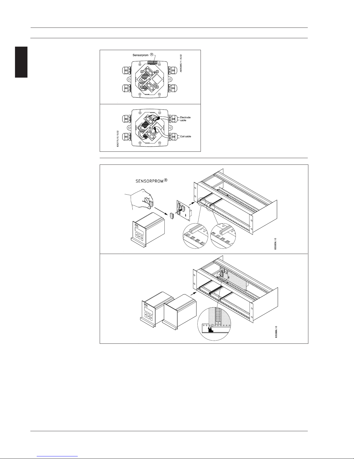
2.3.1 Remote installation -
At the sensor
Fit and connect the electrode and coil cables
as shown in chapter 7 “Electrical connections”
in the handbook.
The unscreened cable ends must be kept as
short as possible.
The electrode cable and the coil cable must be
kept separate to prevent interference.
Tighten the cable glands well to obtain optimum sealing.
Remove the SENSORPROM® unit from the
sensor and mount it on the connection plate in
the transmitter.
2.3.2 Remote installation -
Transmitter in 19"
insert
1. Fit the SENSORPROM® memory unit on the connection board supplied with the transmitter.
The SENSORPROM® unit is supplied with the sensor in the terminal box.
2. Mount the guide rails into the rack system as shown. Distance between guide rails is 20 TE.
Guide rails are supplied with the rack system and not with the transmitter.
3. Mount the connection board as shown.
4. Connect the cables as shown under "Electrical connection", chapter 7 in the handbook.
5. Insert the transmitter into the rack system.
SITRAN S F M MAGFLO
®®
®®
®
7
SFIDK.PS.026.C2.02
ENGLISH
2. Installation
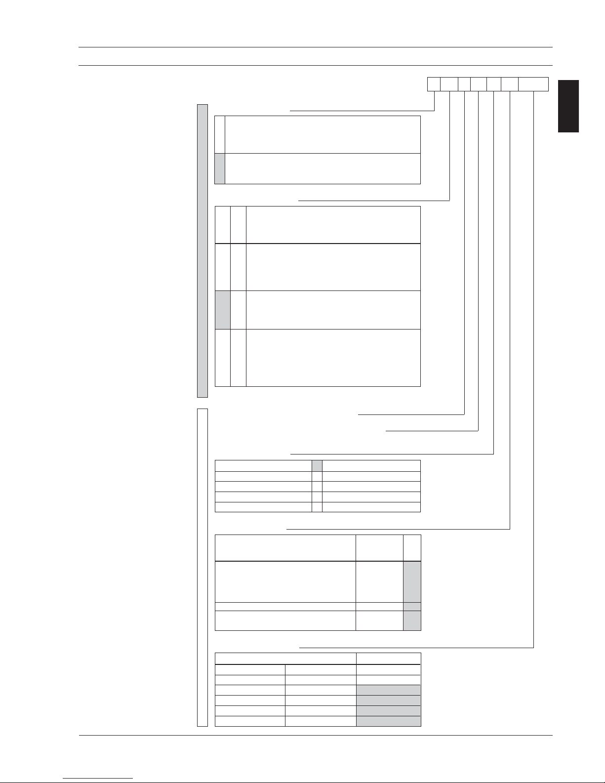
2.4 Ex survey according
to Directive 94/9/EC
(ATEX)
Applies to instruments used in underground mining
operations, as well as their above ground
operations, which can be endangered by mine gas
and/or flammable dusts.
Instrument groups
Applies to instruments used in the remaining areas
which can be endangered by a potentially explosive
atmosphere.
Instruments of this category are for use in
areas where ignitable atmospheres, caused by
a mixture of air and gasses, vapours or mists or
by dust/air mixtures, can exist all of the time or
for long periods of time or else frequently.
Instruments of this category are for use in
areas where ignitable atmospheres caused, by
a mixture of air and gasses, vapours or mists or
by dust/air mixtures, can exist some of the time.
Instruments of this category are for use in
areas where ignitable atmospheres, caused by
a mixture of air and gasses, vapours or mists or
by dust/air mixtures, are not likely to exist.
However, if they do occur then in all probability,
only seldom or for short periods of time.
Instrument category
(The figures in brackets refer to IEC)
Built according to European norm = E
Explosion protected electrial equipment = Ex
Ex protection labelling in square brackets refers to "Associated electrical equipment"
as an example
:
II 2G E Ex ia IIB T3-T6
Type of protection
o Oil encapsulated i Intrinsic safety (ia, ib)
p Pressurized apparatus n Non-incentive equipment
q Powder filling m Encapsulation
d Flameproof enclosure s Special protection
e Increased safety
Explosion groups
Gases and vapours Minimum EN/
(examples) ignition IEC
energy [mJ]
• Ammonia - IIA
• Acetone, aircraft fuel, benzine,
crude oil, diesel oil, ethane, ethanoic
acid, ether, gasolines, heating oil,
hexane, methane, propane 0.18 IIA
• Ethylene, isoprene, town gas 0.06 IIB
• Acetylene, carbon disulphide,
hydrogen 0.02 IIC
Ignition temperature
Maximum surface temperature EN / IEC
450°C 842°FT1
300°C 572°FT2
200°C 392°FT3
135°C 275°FT4
100°C 212°FT5
85°C 185°FT6
I
II
EN 50014 Directive 94/9/EC (ATEX)
Definition
1G
(0)
Labelling
with gases
Labelling
with dusts
1D
(20)
2G
(1)
2D
(21)
3G
(2)
3D
(22)
SITRAN S F M MAGFLO
®®
®®
®
8
SFIDK.PS.026.C2.02
ENGLISH
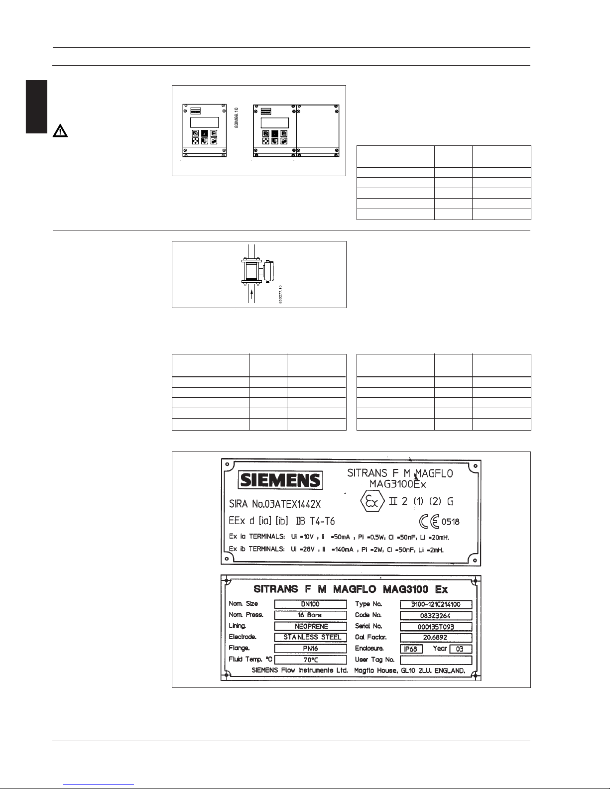
2.6 Device identification
Sensor MAG 1100 Ex or
MAG 3100 Ex label
2. Installation
Can
only
be installed in safe area!
All MAG 1100 Ex and MAG 3100 Ex sensors
have the following ratings and input parameters:
2.5 Overview and
intrinsically safe data
MAG 6000 19" IP 20
& I P 6 5 [EEx ia] IIB
Category 2 equipment
Sensors may be installed in zone 1 and zone 2.
Sensors intrinsically safe data
See table below.
MAG 1100 & MAG 3100
EEx ia IIB T3...T6
Terminals 85-86 82-83
MAG barriers ib coil ia electrode
U
o
28 V 9.3 V
I
o
138 mA 40 mA
P
o
0.4 W
L
o
4 mH 23 mH
C
o
100 nF 500 nF
Terminals 85-86 82-83
MAG sensor coil electrode
U
i
28 V 10 V
I
i
140 mA 50 mA
P
i
2 W 0.5 W
L
i
2 mH 20 mH
C
i
50 nF 50 nF
MAG 1100 DN 6 - 100
MAG 3100 DN 15 - 300 Ex ib
Terminals 85-86 82-83
MAG sensor coil electrode
U
i
- 10 V
I
i
- 50 mA
P
i
- 0.5 W
L
i
- 20 mH
C
i
- 50 nF
MAG 3100 DN 350 - 2000 Ex e ia
IS data transmitter
IS data sensor
Specifications:
Supply: 115-230 V or 24 V
Ambient temperature: −20 to 50°C
Enclosure: IP 20 or IP 65
SITRAN S F M MAGFLO
®®
®®
®
9
SFIDK.PS.026.C2.02
ENGLISH
SITRANS F M MAGFLO® sensors carry the following approvals
MAG 1100 Ex for mounting in Ex areas
DN 6 - DN 100
EEx [ia] [ib] IIB T4...T6, II 2 (1)(2)
SIRA 03 ATEX 1423X CE 0518
Temperature ratings are as follows:
T4 (max. surface < 135°C) for liquid temperatures lower than 100°C
T5 (max. surface < 100°C) for liquid temperatures lower than 82°C
T6 (max. surface < 85°C) for liquid temperatures lower than 67°C
For an ambient temperature of –20°C to + 50°C
MAG 3100 Ex for mounting in Ex areas
DN 15 - DN 300
EEx-d [ia] [ib] IIB T4...T6, II 2 (1)(2)
SIRA 03 ATEX 1442X CE 0518
Temperature ratings are as follows*):
T4 (max. surface < 135°C) for liquid temperatures lower than 100°C
T5 (max. surface < 100°C) for liquid temperatures lower than 87°C
T6 (max. surface < 85°C) for liquid temperatures lower than 72°C
For an ambient temperature of –20°C to +50°C
DN 350 - DN 2000
EEx e ia IIC T3…T6, II 2 GD IP 65 T(**)
O
C
SIRA 03 ATEX 3339X CE 0518
where (**) represents the pipeline temperature + 5K for the purposes of the dust approval
Temperature ratings are as follows*):
T3 (max. surface < 200°C) for liquid temperatures lower than 190°C
T4 (max. surface < 135°C) for liquid temperatures lower than 125°C
T5 (max. surface < 100°C) for liquid temperatures lower than 90°C
T6 (max. surface < 85°C) for liquid temperatures lower than 75°C
For an ambient temperature of –20°C to +40°C
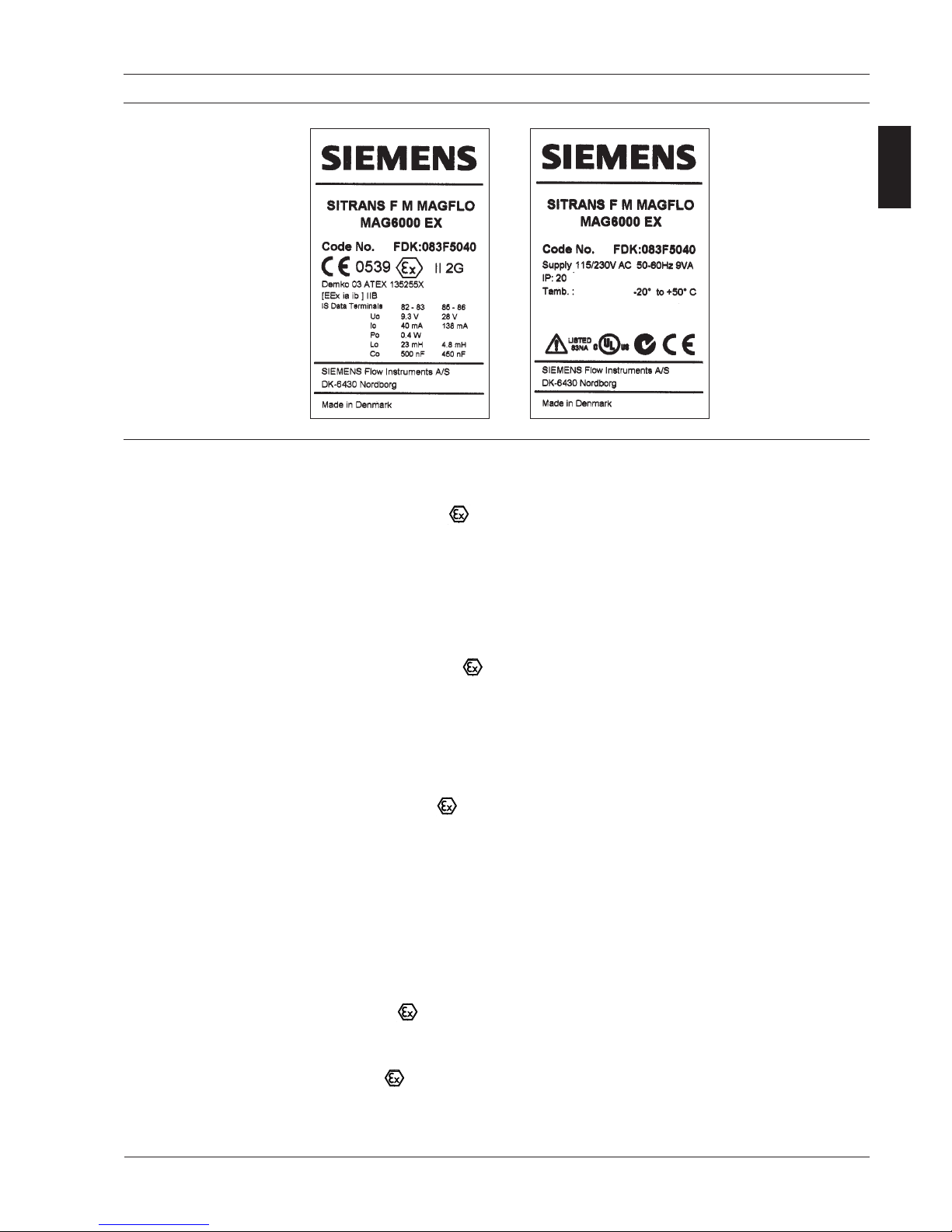
MAG 6000 & safety barriers carry the following approvals
For use with MAG 1100 Ex (all sizes) and MAG 3100 Ex sizes DN 15 - DN 300 for mounting in
the safe area
[EEx ia ib] IIB, II 2 G
DEMKO 03 ATEX 135255X CE539
For use with MAG 3100 Ex sizes DN 350 - DN 2000, for mounting in the safe area
[EEx ia] IIC, II 2 G
DEMKO 03 ATEX 135254X CE539
*) Note
Temperature ratings may be limited by the lining selected, see section 4.2.2.
2.7 Approvals
2. Installation
Transmitter
MAG 6000 19" IP 20 and
IP 65 label

SITRAN S F M MAGFLO
®®
®®
®
10
SFIDK.PS.026.C2.02
ENGLISH
2.8 Special conditions for
safe use
MAG 3100 Ex DN 40 - DN 300
The relation between assigned temperature ambient temperature and media temperature:
Temperature class Ambient temperature range Media temperature range
T6 −20 °C to +50 °C −20 °C to +60 °C
T5 −20 °C to +50 °C −20 °C to +75 °C
T4 −20 °C to +50 °C −20 °C to +100 °C
This electrode circuit "ia" is connected to the media inside the sensor. The screen for the "ib" circuit
is connected to chassis and the installations shall therefore take that into account.
2. Installation
Safety Barrier type FDK:083F50_ _ for MAG sensors
Special conditions for safe use:
• The ambient temperature range is −20 °C to +50 °C.
• The safety barrier shall be connected to the PE earth (light blue) according to local installation
equipments. IEC 60079-14 can be used as guideline.
• The PE earth shall be connected to the PE at the sensor according to local installation
equipments. IEC 60079-14 can be used as guideline.
• The intrinsic safety wiring shall be separated from non intrinsic safety wiring according to local
installation equipments.
• The apparatus must be installed in plastic enclosure code FDK:083F5038 with an Ingress
Protection suitable for the environment. The plastic box FDK:083F5038 has been evaluated
for IP 65 according to EN 60529: 1989.
SITRAN S F M MAGFLO
®®
®®
®
11
SFIDK.PS.026.C2.02
ENGLISH
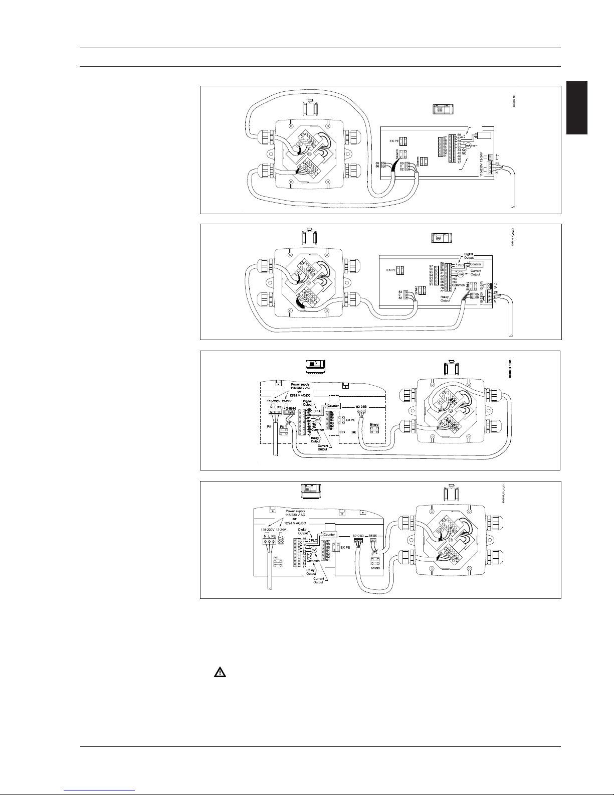
It is an absolute requirement that the wires/terminals of the intrinsically safe circuits cannot get
into contact with the wires of the other cables. The distance between cables/wires therefore must
be at least 50 mm.
It is recommended to fasten the cables/wires in a way that they, even in case of an error, cannot
get into contact with each other. Make the wire ends as short as possible.
1. Connection terminals to:
• Power supply
• In- and output
2. Connection terminals to:
Sensors
Intrinsically safe terminals!
3. Electrical connection
3. Electrical connection
3.1.1 19” IP 20 version
EEx (ia/ib) DN
≤≤
≤≤
≤ 300
3.1.3 19” IP 66 version
EEx (ia/ib) DN
≤ ≤
≤ ≤
≤ 300
3.1.4 19” IP 66 version
EEx e (ib) DN
≥≥
≥≥
≥ 350
3.1.2 19” IP 20 version
EEx e (ib) DN
≥≥
≥≥
≥ 350
 Loading...