

Siemens SITRANS F M MAG 5100 W,SITRANS F Series Operating Instructions Manual

Electromagnetic flowmeters
SITRANS F M MAG 5100 W
Operating Instructions • 11/2010
SITRANS F
SITRANS F


SITRANS F
Electromagnetic Flowmeters
SITRANS F M MAG 5100 W
Operating Instructions
Introduction
Safety notes
Description
Installing/Mounting
Connecting
Service and maintenance
Troubleshooting/FAQs
Technical data
Appendix
1
2
3
4
5
6
7
8
A
Electromagnetic sensor type SITRANS F M MAG
5100 W for use with transmitter types SITRANS F M
MAG 5000/6000/6000I
11/2010
A5E03063678-02

Legal information
Warning notice system
This manual contains notices you have to observe in order to ensure your personal safety, as well as to prevent
damage to property. The notices referring to your personal safety are highlighted in the manual by a safety alert
symbol, notices referring only to property damage have no safety alert symbol. These notices shown below are
graded according to the degree of danger.
DANGER
indicates that death or severe personal injury will result if proper precautions are not taken.
WARNING
indicates that death or severe personal injury may result if proper precautions are not taken.
CAUTION
with a safety alert symbol, indicates that minor personal injury can result if proper precautions are not taken.
CAUTION
without a safety alert symbol, indicates that property damage can result if proper precautions are not taken.
NOTICE
indicates that an unintended result or situation can occur if the corresponding information is not taken into
account.
If more than one degree of danger is present, the warning notice representing the highest degree of danger will
be used. A notice warning of injury to persons with a safety alert symbol may also include a warning relating to
property damage.
Qualified Personnel
The product/system described in this documentation may be operated only by personnel qualified for the specific
task in accordance with the relevant documentation for the specific task, in particular its warning notices and
safety instructions. Qualified personnel are those who, based on their training and experience, are capable of
identifying risks and avoiding potential hazards when working with these products/systems.
Proper use of Siemens products
Note the following:
WARNING
Siemens products may only be used for the applications described in the catalog and in the relevant technical
documentation. If products and components from other manufacturers are used, these must be recommended
or approved by Siemens. Proper transport, storage, installation, assembly, commissioning, operation and
maintenance are required to ensure that the products operate safely and without any problems. The permissible
ambient conditions must be adhered to. The information in the relevant documentation must be observed.
Trademarks
All names identified by ® are registered trademarks of the Siemens AG. The remaining trademarks in this
publication may be trademarks whose use by third parties for their own purposes could violate the rights of the
owner.
Disclaimer of Liability
We have reviewed the contents of this publication to ensure consistency with the hardware and software
described. Since variance cannot be precluded entirely, we cannot guarantee full consistency. However, the
information in this publication is reviewed regularly and any necessary corrections are included in subsequent
editions.
Siemens AG order number: A5E03063678 Copyright © Siemens AG 2010.
Industry Sector Ⓟ 11/2010 Technical data subject to change
Postfach 48 48
90026 NÜRNBERG
GERMANY

Table of contents
1 Introduction................................................................................................................................................ 5
1.1 Items supplied................................................................................................................................5
1.2 History............................................................................................................................................5
1.3 Further Information ........................................................................................................................6
2 Safety notes............................................................................................................................................... 7
2.1 Laws and directives .......................................................................................................................7
2.2 Installation in hazardous area........................................................................................................9
2.3 Certificates ...................................................................................................................................10
3 Description............................................................................................................................................... 11
3.1 System components ....................................................................................................................11
3.2 Theory of operation......................................................................................................................12
4 Installing/Mounting................................................................................................................................... 15
4.1 Installation safety precautions......................................................................................................15
4.2 Determining a location .................................................................................................................16
4.3 Orienting the sensor.....................................................................................................................18
4.4 Mounting ......................................................................................................................................19
4.5 Potential equalization...................................................................................................................21
5 Connecting .............................................................................................................................................. 23
5.1 Remote installation ......................................................................................................................24
5.2 Installation check .........................................................................................................................26
5.3 Potting..........................................................................................................................................26
5.4 Direct burial..................................................................................................................................28
6 Service and maintenance ........................................................................................................................ 29
6.1 Maintenance.................................................................................................................................29
6.2 Recalibration ................................................................................................................................29
6.3 Transportation/storage.................................................................................................................29
Unit repair.....................................................................................................................................30
6.4
6.5 Technical support.........................................................................................................................30
6.6 Return procedures .......................................................................................................................31
7 Troubleshooting/FAQs............................................................................................................................. 33
7.1 Sensor check ...............................................................................................................................33
7.2 Fluctuating process values ..........................................................................................................35
SITRANS F M MAG 5100 W
Operating Instructions, 11/2010, A5E03063678-02
3

Table of contents
8 Technical data ......................................................................................................................................... 37
8.1 MAG 5100 W............................................................................................................................... 37
8.2 Cable data................................................................................................................................... 40
8.3 Effect of temperature on work
ing pres
sure................................................................................. 41
8.4 Process fluid conductivity............................................................................................................ 42
8.5 Liner selection ............................................................................................................................. 43
8.6 Electrode selection...................................................................................................................... 43
8.7 Sizing tables................................................................................................................................ 44
8.8 Dimensions and weight............................................................................................................... 46
A Appendix.................................................................................................................................................. 51
A.1 Flange mating dimensions (metric)............................................................................................. 51
A.2 Factory settings........................................................................................................................... 53
A.3 Coil resistance............................................................................................................................. 55
A.4 Ordering ...................................................................................................................................... 57
Glossary .................................................................................................................................................. 59
Index........................................................................................................................................................ 61
SITRANS F M MAG 5100 W
4 Operating Instructions, 11/2010, A5E03063678-02

Introduction
These instructions contain all the information you need for using the device.
The instructions are aimed at persons mechanically installing the device, connecting it
electronically, configuring the parameters and commissioning it as well as service and
1.1 Items supplied
maintenance engineers.
Note
It is the responsibility of the customer that the instructions and directions provi
manual are read, understood and followed by the relevant personnel before installing the
device.
SITRANS F M MAG 5100 W
Calibration report
SITRANS F M literature CD
Quick Start guide
1
ded in the
1.2 History
The contents of these instructions are regularly reviewed and corrections are included in
subsequent editions. We welcome all suggestions for improvement.
The following table shows the most important changes in the documentation compared to
each previous edition.
Edition Remarks
11/2010 Minor updates
07/2010 First edition
Replaces MAG 5100 W part of SITRANS F M Handbook (A5E02435647) and MAG 5100
W instruction (A5E00718677)
SITRANS F M MAG 5100 W
Operating Instructions, 11/2010, A5E03063678-02
5

Introduction
1.3 Further Information
1.3 Further Information
The contents of these Operating Instructions shall not become part of or modify any prior or
existing agreement, commitment or legal relationship. All obligations on the part of Siemens
AG are contained in the respective sales contract which also contains the complete and
solely applicable warranty conditions. Any statements contained herein do not create new
warranties or modify the existing warranty.
Product information on the Internet
The Operating Instructions are available on the CD-ROM shipped with the device, and on
the Internet on the Siemens homepage, where further information on the range of SITRANS
F flowmeters may also be found:
Product information on the internet (http://www.siemens.com/flowdocumentation
Worldwide contact person
If you need more information or have particular problems not covered sufficiently by the
operating instructions, please get in touch with your contact person. You can find contact
information for your local contact person on the Internet:
Local contact person (http://www.automation.siemens.com/partner
See also
Technical support (Page 30)
)
)
SITRANS F M MAG 5100 W
6 Operating Instructions, 11/2010, A5E03063678-02

Safety notes
2.1 Laws and directives
CAUTION
Correct, reliable operation of the product requires proper transport, storage, positioning and
assembly as well as careful operation and maintenance. Only qualified personnel should
install or operate this instrument.
Note
Alterations to the product, including opening or improper repairs of the product, are not
permitted.
If this requirement is not observed, the CE mark and the manufacturer's warranty will expire.
2
General requirements
Installation of the equipment must comply with national regulations.
Instrument safety standards
The device has been tested at the factory, based on the safety requirements. In order to
maintain this condition over the expected life of the device the requirements described in
these Operating Instructions must be observed.
CAUTION
Material compatibility
Siemens Flow Instruments can provide assistance with the selection of wetted sensor
parts. However, the full responsibility for the selection rests with the customer and Siemens
Flow Instruments can take no responsibility for any failure due to material incompatibility.
SITRANS F M MAG 5100 W
Operating Instructions, 11/2010, A5E03063678-02
7

Safety notes
2.1 Laws and directives
CE marked equipment
All meters carry either a CE mark or a CE mark followed by eg.200
● CE200: This indicates that the product conforms to:
– PED 97/23/EC
– LVD 2006/95/EC
– EMC 2004/108/EC
● CE: This indicates that the product conforms to:
– LVD 2006/95/EC
– EMC 2004/108/EC
Compliance with PED directive
"Pressure Equipment Directive" (PED) is mandatory for all pressure equipment sold within
the EU and EFTA.
Siemens Flow Instruments products confirms to PED by following the tables below.
Table 2- 1 MAG 5100 W (7ME6580 only DN15 ... 600 (½" ... 24"))
Flange mm PN 10 PN 16 PN 40 150 lb 300 lb
15 N/A N/A SEP SEP N/A
25 N/A N/A SEP SEP N/A
40 N/A N/A SEP SEP N/A
50 N/A SEP N/A SEP N/A
65 N/A SEP N/A SEP N/A
80 N/A SEP N/A SEP N/A
100 SEP SEP N/A SEP N/A
125 N/A SEP N/A PED N/A
150 N/A PED N/A PED N/A
200 SEP PED N/A PED N/A
250 LVD PED N/A PED N/A
300 LVD PED N/A PED N/A
350 LVD PED N/A PED N/A
400 LVD PED N/A PED N/A
450 LVD PED N/A PED N/A
500 LVD PED N/A PED N/A
600 LVD PED N/A PED N/A
700 LVD PED* N/A N/A PED
750 N/A N/A N/A N/A PED
SITRANS F M MAG 5100 W
8 Operating Instructions, 11/2010, A5E03063678-02

Safety notes
2.2 Installation in hazardous area
800 LVD PED* N/A N/A PED
900 LVD PED* N/A N/A PED
1000 LVD PED* N/A N/A PED
1050 N/A N/A N/A N/A PED
1100 N/A N/A N/A N/A PED
1200 LVD PED* N/A N/A PED
The key to the tables is as follows:
PED Product covered by PED and only available as fully PED-conforming
PED* Product covered by PED but available as either conforming or non-conforming to
PED
SEP Excluded from PED under Sound Engineering Practice
LVD Excluded from PED under the Low Voltage Directive
2.2 Installation in hazardous area
WARNING
Equipment used in hazardous areas must be approved for use in hazardous area and
marked accordingly. It is required that the special conditions for safe use provided in the
manual and in the FM / CSA certificates are followed!
SITRANS F M MAG 5100 W
Operating Instructions, 11/2010, A5E03063678-02
9
Safety notes
2.3 Certificates
Hazardous area approvals
The device is approved for use in hazardous area and has the following approvals:
● MAG 5100 W DN 15 ... 1200: FM / CSA Class I, Div. 2
WARNING
Make sure the hazardous area approval is suitable for the environment in which the
device will be installed.
WARNING
All approvals are based on non-flammable processes only!
WARNING
Potential equalization
In operation, the output is earthed through the conductive medium being measured and
therefore potential equalisation is necessary throughout the hazardous area.
The apparatus housing shall be connected to the potential equalising conductor in the
hazardous area.
WARNING
Laying of cables
Cables for use in hazardous area must satisfy the requirements for having a proof
voltage < AC 500 V applied between the conductor/ground, conductor/shield and
shield/ground.
Connect the devices that are operated in hazardous areas as per the stipulations
applicable in the country of operation.
2.3 Certificates
Certificates are posted on the Internet and on the documentation CD-ROM shipped with the
device.
See also
Technical data (Page 37)
Certificates on the Internet (http://www.siemens.com/processinstru
mentation/certificates)
SITRANS F M MAG 5100 W
10 Operating Instructions, 11/2010, A5E03063678-02

Description
The main applications of the SITRANS F M electromagnetic flow sensors can be found in the
following fields:
● Process industry
● Chemical industry
● Steel industry
● Mining
● Utility
● Power generation & distribution
● Oil & gas / HPI
● Water & waste water
● Pulp & paper
3.1 System components
3
The SITRANS F M USM II flowmeter system includes:
● Transmitter (types: SITRANS F M MAG 5000/6000 or MAG 6000 I)
● Sensor (types: SITRANS F M MAG 1100/1100F, MAG 3100/3100 P or MAG 5100 W)
● Communication module (optional) (types: HART, PROFIBUS PA/DP, MODBUS RTU RS
485, Foundation Fieldbus H1, Devicenet)
● SENSORPROM memory unit
Communication solutions
The SITRANS F USM II range of add on modules, presently including HART, Foundation
Fieldbus. MODBUS RTU RS 485, PROFIBUS PA / DP and Devicenet, are all applicable with
the SITRANS F M MAG 6000 transmitter.
SITRANS F M MAG 5100 W
Operating Instructions, 11/2010, A5E03063678-02
11
Description
3.2 Theory of operation
The SITRANS F M MAG 5100 W sensor housing and flanges are designed in carbon steel
and terminal box in fibre glass reinforced polyamide. Measuring pipe is made of stainless
steel (AISI 304) and liners are available in NBR Hard Rubber, Ebonite Hard Rubber, or
EPDM, which makes the sensor highly resistant to a wide range of chemicals. Electrodes are
made of Hastelloy.
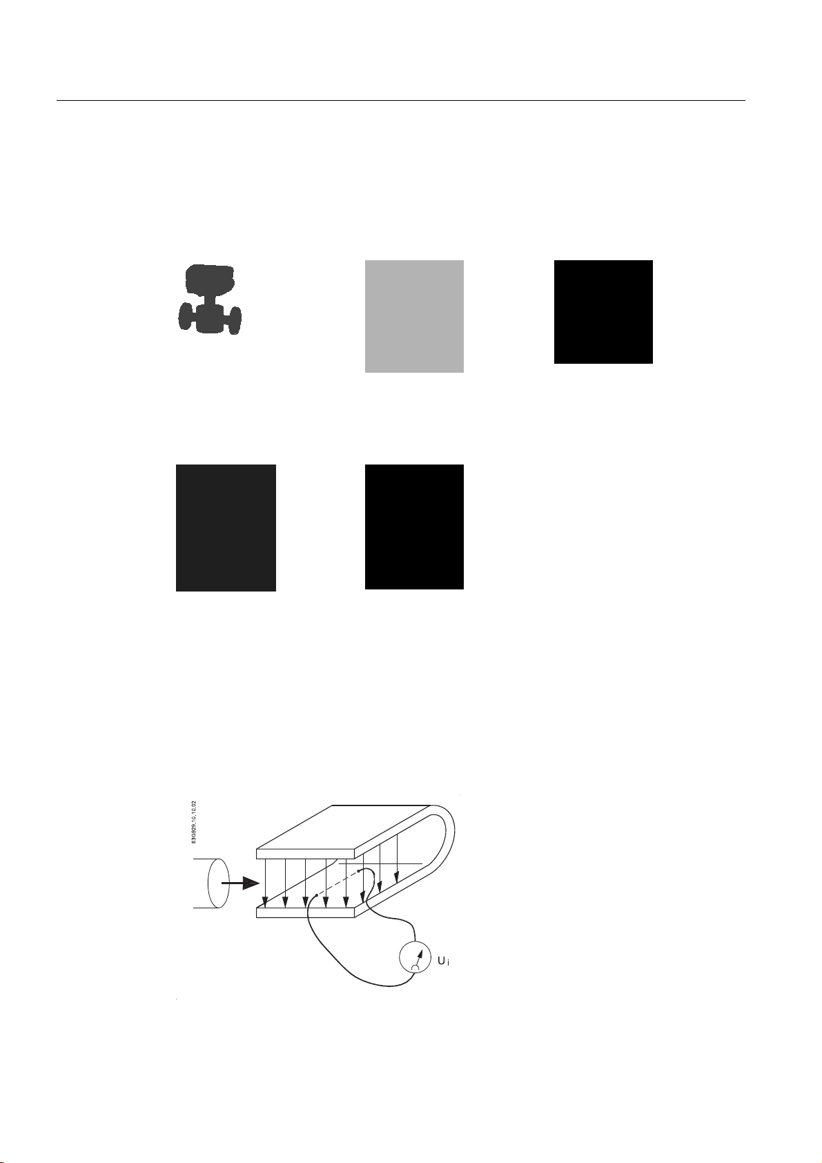
MAG 5100W DN15 ... 40 MAG 5100W DN50 ... 300 MAG 5100W
MAG 5100W compact
installation with MAG
5000/6000 IP67
The sensors carry a wide range of approvals, see Technical data (Page 37).
3.2 Theory of operation
MAG 5100W compact
installation with MAG 6000 I
DN350 ... 1200
(7ME6520)
MAG 5100W DN25 ... 2000
(7ME6580)
The flow measuring principle is based on Faraday’s law of electromagnetic induction.
0DJQHWLF)LHOG
)ORZ
SITRANS F M MAG 5100 W
12 Operating Instructions, 11/2010, A5E03063678-02

Description
3.2 Theory of operation
Ui = When an electrical conductor of length L is moved at velocity v, perpendicular to the
lines of flux through a magnetic field of strength B, the voltage Ui is induced at the ends of
the conductor
= L x B x v
U
i
● Ui = Induced voltage
● L = Conductor length = Inner pipe diameter = k
● B = Magnetic field strength = k
● v = Velocity of conductor (media)
● k = k
Ui = k x v, the electrode signal is directly proportional to the fluid velocity
Operating principle
The coil current module generates a pulsating magnetizing current that drives the coils in the
sensor. The current is permanently monitored and corrected. Errors or cable faults are
registered by the self-monitoring circuit.
Input circuit amplifies the flow-proportional induced voltage signal from the electrodes. The
input impedance is extremely high: >10
conductivities as low as 5 µS/cm. Measuring errors due to cable capacitance are eliminated
due to active cable screening.
Digital signal processor converts the analog flow signal to a digital signal and suppresses
electrode noise through a digital filter. Inaccuracies in the transmitter as a result of long-term
drift and temperature drift are monitored and continuously compensated for via the selfmonitoring circuit. The analog to digital conversion takes place in an ultra low noise ASIC
with 23 bit signal resolution. This has eliminated the need for range switching. The dynamic
range of the transmitter is therefore unsurpassed with a turn down ratio of minimum 3000:1.
x k2
1
1
2
14
Ω which allows flow measurements on fluids with
SITRANS F M MAG 5100 W
Operating Instructions, 11/2010, A5E03063678-02
13

Description
3.2 Theory of operation
SITRANS F M MAG 5100 W
14 Operating Instructions, 11/2010, A5E03063678-02
Installing/Mounting
SITRANS F flowmeters with minimum IP67/NEMA 4X enclosure rating are suitable for inand outdoor installations.
● Make sure that pressure and temperature specifications indicated on the device
nameplate / label will not be exceeded.
4.1 Installation safety precautions
WARNING
Installation in hazardous location
Special requ
transmitter. See "Installation in hazardous area" (Page 9)
WARNING
In applications with working pressures/media that can be dangerous to people,
surroundings, equipment or others in case of pipe fracture, we recommend that special
precautions such as special placement, shielding or installation of a security guard or a
security valve are taken when the sensor is mounted.
irements apply to the location and interconnection of sensor and
4
● Ensure that stresses and loading caused by e.g. earthquakes, traffic, high winds and fire
damage if appropriate are taken into account during installation.
● Ensure that the flowmeter is installed such that it does not act as a focus for pipeline
stresses. External loadings are not taken into account in the flowmeter design.
● Provide adequate protection to minimise any risk of contact with hot surfaces.
SITRANS F M MAG 5100 W
Operating Instructions, 11/2010, A5E03063678-02
WARNING
Prevent personal injuries by assuring that operation belo
place, if working with vacuum or fluids boiling readily.
w pressure guards cannot take
15
Installing/Mounting
4.2 Determining a location
4.2 Determining a location
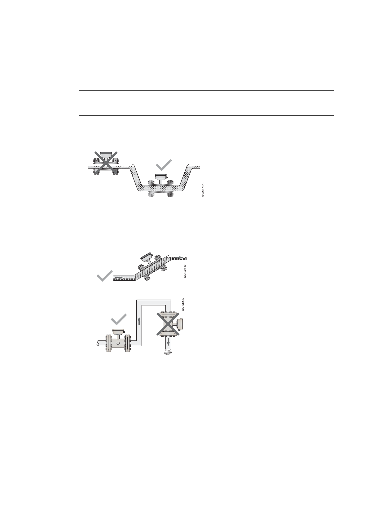
NOTICE
The sensor must always be completely filled with liquid.
● Locate the the flowmeter in u-shaped pipes if pipes are only partially filled or have free
outlet
Figure 4-1 Correct installation in U-tube
● Avoid the following installations
– Installation at the highest point in the pipe system
– Installation in vertical pipes with free outlet
Figure 4-2 Correct installation with filled pipes
Figure 4-3 Correct installation at low point in system before outlet
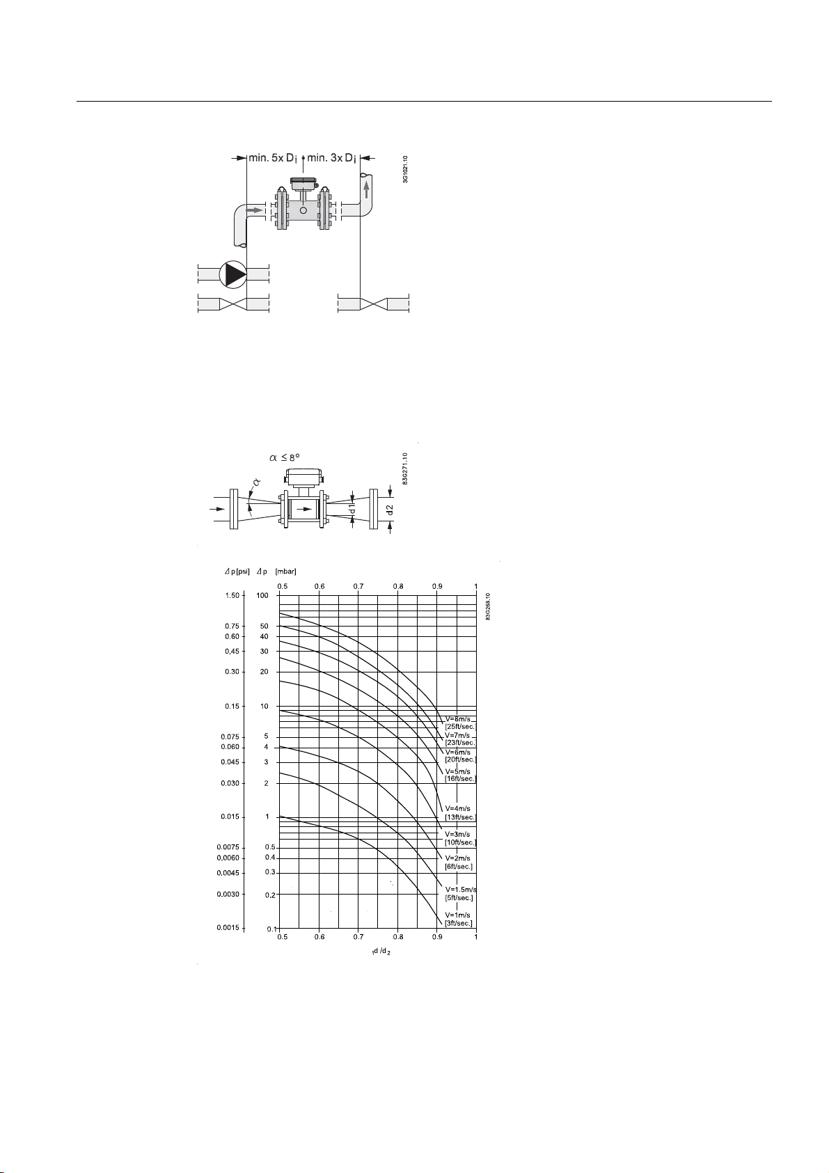
Inlet and outlet conditions
To achieve accurate flow measurement it is essential to have straight lengths of inlet and
outlet pipes and a certain distance to pumps and valves.
It is also important to centre the flowmeter in relation to pipe flanges and gaskets.
SITRANS F M MAG 5100 W
16 Operating Instructions, 11/2010, A5E03063678-02
Installing/Mounting
4.2 Determining a location
Figure 4-4 Inlet and outlet conditions
Installation in large pipes
The flowmeter can be installed between two reducers (e.g. DIN 28545). At 8° the following
pressure drop curves apply. The curves are applicable to water.
Example:
A flow of 3 m/s (V) in a sensor with a diameter reduction from DN 100 to DN 80 (d
gives a pressure drop of 2.9 mbar.
SITRANS F M MAG 5100 W
Operating Instructions, 11/2010, A5E03063678-02
= 0.8)
1/d2
17
Installing/Mounting
4.3 Orienting the sensor
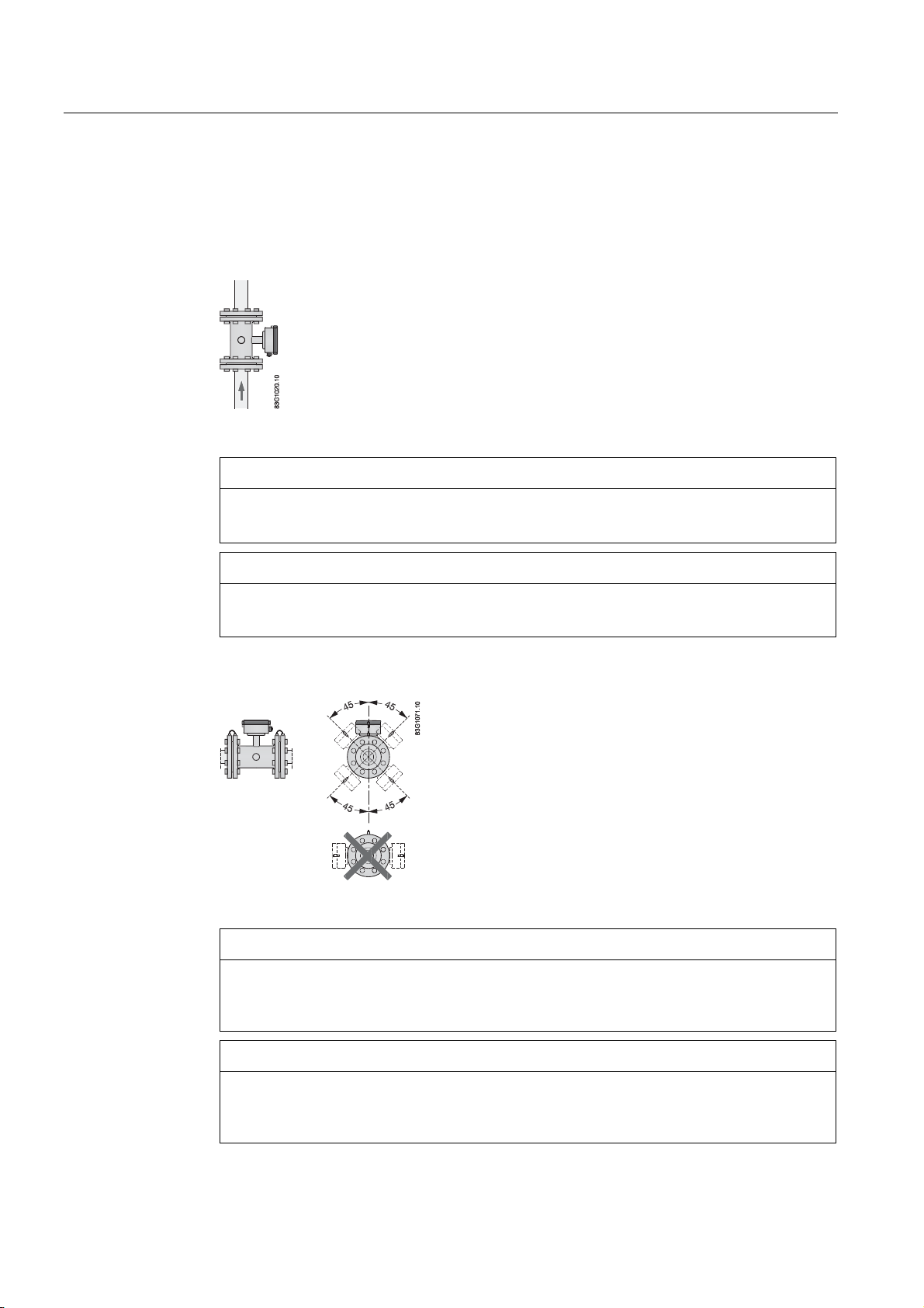
4.3 Orienting the sensor
The sensor operates in all orientations, but Siemens has the following recommendations:
● Vertical installation with an upwards flow
Figure 4-5 Vertical orientation, upwards flow
CAUTION
Abrasive liquids / liquids containing solid particles
A vertical installation minimizes wear and deposits in the sensor
NOTICE
Gas/air bubbles in the liquid
A vertical installation minimizes any negative effect of gas/air bubbles in the liquid
● Horizontal installation, terminal box upwards or downwards
Figure 4-6 Horizontal installation, various terminal box positions
CAUTION
Do NOT mount the sensor with the terminal box sideways
This will position the electrodes at the top where there is possibility for air bubbles and
at the bottom where there is possibility for mud, sludge, sand etc.
NOTICE
Empty pipe detection
For applications with empty pipe detection, the sensor can be tilted 45°, as shown
above.
SITRANS F M MAG 5100 W
18 Operating Instructions, 11/2010, A5E03063678-02
 Loading...