

Siemens SITRANS F M MAG 5000 Blind, SITRANS F M MAG 5000 CT, SITRANS F M MAG 6000 Blind, SITRANS F M MAG 6000 CT, SITRANS F M MAG 5000 SV Operating Instructions Manual
...
Electromagnetic Flowmeters
SITRANS F M MAG 5000/6000
Operating Instructions • 01/2010
SITRANS F


SITRANS F
Flowmeters
SITRANS F M MAG 5000/6000
Operating Instructions
Introduction
Safety notes
Description
Installing/Mounting
Connecting
Commissioning
Service and maintenance
Functions
Alarm, error, and system
messages
Troubleshooting/FAQs
Technical data
Spare parts/Accessories
Menu diagrams
Appendix
1
2
3
4
5
6
7
8
9
10
11
12
A
B
Electromagnetic flow transmitter designed for use with
flow sensor types
MAG 1100/1100 F/3100/3100 P/5100 W
Compact and remote i
nstallation
01/2010
SFIDK.PS.026.G1.02
Legal information
Warning notice system
This manual contains notices you have to observe in order to ensure your personal safety, as well as to prevent
damage to property. The notices referring to your personal safety are highlighted in the manual by a safety alert
symbol, notices referring only to property damage have no safety alert symbol. These notices shown below are
graded according to the degree of danger.
DANGER
indicates that death or severe personal injury will result if proper precautions are not taken.
WARNING
indicates that death or severe personal injury may result if proper precautions are not taken.
CAUTION
with a safety alert symbol, indicates that minor personal injury can result if proper precautions are not taken.
CAUTION
without a safety alert symbol, indicates that property damage can result if proper precautions are not taken.
NOTICE
indicates that an unintended result or situation can occur if the corresponding information is not taken into
account.
If more than one degree of danger is present, the warning notice representing the highest degree of danger will
be used. A notice warning of injury to persons with a safety alert symbol may also include a warning relating to
property damage.
Qualified Personnel
The product/system described in this documentation may be operated only by personnel qualified for the specific
task in accordance with the relevant documentation for the specific task, in particular its warning notices and
safety instructions. Qualified personnel are those who, based on their training and experience, are capable of
identifying risks and avoiding potential hazards when working with these products/systems.
Proper use of Siemens products
Note the following:
WARNING
Siemens products may only be used for the applications described in the catalog and in the relevant technical
documentation. If products and components from other manufacturers are used, these must be recommended
or approved by Siemens. Proper transport, storage, installation, assembly, commissioning, operation and
maintenance are required to ensure that the products operate safely and without any problems. The permissible
ambient conditions must be adhered to. The information in the relevant documentation must be observed.
Trademarks
All names identified by ® are registered trademarks of the Siemens AG. The remaining trademarks in this
publication may be trademarks whose use by third parties for their own purposes could violate the rights of the
owner.
Disclaimer of Liability
We have reviewed the contents of this publication to ensure consistency with the hardware and software
described. Since variance cannot be precluded entirely, we cannot guarantee full consistency. However, the
information in this publication is reviewed regularly and any necessary corrections are included in subsequent
editions.
Siemens AG Ordernumber: A5E02338368 Copyright © Siemens AG 2010.
Industry Sector Ⓟ 01/2010 Technical data subject to change
Postfach 48 48
90026 NÜRNBERG
GERMANY

Table of contents
1 Introduction................................................................................................................................................ 7
1.1 Preface...........................................................................................................................................7
1.2 Items supplied................................................................................................................................7
1.3 History............................................................................................................................................8
1.4 Further Information ........................................................................................................................9
2 Safety notes............................................................................................................................................. 11
2.1 Laws and directives .....................................................................................................................11
2.2 Installation in hazardous location.................................................................................................12
3 Description............................................................................................................................................... 13
3.1 System components ....................................................................................................................13
3.2 Operating principle.......................................................................................................................13
3.3 Applications..................................................................................................................................13
3.4 Features.......................................................................................................................................14
3.5 MAG 5000/MAG 6000 versions ...................................................................................................15
4 Installing/Mounting................................................................................................................................... 17
4.1 Installation conditions...................................................................................................................18
4.2 MAG 5000/6000 compact ............................................................................................................20
4.3 Remote installation ......................................................................................................................22
4.4 MAG 5000/6000 CT.....................................................................................................................27
4.4.1 Installing hardware key ................................................................................................................27
4.4.2 Seal device...................................................................................................................................28
4.5 Turning transmitter/keypad ..........................................................................................................29
5 Connecting .............................................................................................................................................. 33
5.1 Electrical connection....................................................................................................................34
5.2 Connection of add-on modules....................................................................................................35
6 Commissioning ........................................................................................................................................ 37
MAG 5000/6000 Blind..................................................................................................................37
6.1
6.2 Local user interface......................................................................................................................38
6.3 Menu structure .............................................................................................................................39
6.4 Changing password .....................................................................................................................40
6.5 Changing basic settings...............................................................................................................40
6.6 Changing operator menu setup ...................................................................................................42
6.7 Changing language......................................................................................................................43
SITRANS F M MAG 5000/6000
Operating Instructions, 01/2010, SFIDK.PS.026.G1.02
3

Table of contents
7 Service and maintenance ........................................................................................................................ 45
7.1 Transmitter check list .................................................................................................................. 45
7.2 Technical support........................................................................................................................ 46
7.3 Return procedures ...................................................................................................................... 48
7.4 Recalibration ............................................................................................................................... 48
8 Functions................................................................................................................................................. 49
8.1 Output settings ............................................................................................................................ 49
8.2 External input .............................................................................................................................. 50
8.3 Sensor characteristics................................................................................................................. 51
8.4 Reset mode................................................................................................................................. 52
8.5 Service mode .............................................................................................................................. 53
8.6 MAG 5000 CT and MAG 6000 CT settings................................................................................. 53
8.7 MAG 6000 SV ............................................................................................................................. 54
9 Alarm, error, and system messages ........................................................................................................ 55
9.1 Diagnostics.................................................................................................................................. 55
9.2 List of error numbers................................................................................................................... 57
10 Troubleshooting/FAQs............................................................................................................................. 59
11 Technical data ......................................................................................................................................... 61
11.1 Technical specifications .............................................................................................................. 61
11.2 Accuracy...................................................................................................................................... 64
11.3 Output characteristics ................................................................................................................. 66
11.4 Cable data................................................................................................................................... 68
11.5 Cable requirements..................................................................................................................... 68
12 Spare parts/Accessories.......................................................................................................................... 69
12.1 Ordering ...................................................................................................................................... 69
12.2 Accessories................................................................................................................................. 69
12.3 Spare parts
.................................................................................................................................. 70
12.4 Sun shield.................................................................................................................................... 71
A Menu diagrams........................................................................................................................................ 73
A.1 Overview MAG 5000/6000.......................................................................................................... 73
A.2 Overview MAG 5000/6000 CT.................................................................................................... 75
A.3 Change password ....................................................................................................................... 76
A.4 Basic settings.............................................................................................................................. 77
A.5 Operator menu setup .................................................................................................................. 78
A.6 Language mode .......................................................................................................................... 79
A.7 Current output ............................................................................................................................. 79
SITRANS F M MAG 5000/6000
4 Operating Instructions, 01/2010, SFIDK.PS.026.G1.02

Table of contents
A.8 Digital output - pulse ....................................................................................................................79
A.9 Digital output - frequency.............................................................................................................80
A.10 Error level.....................................................................................................................................80
A.11 Error number................................................................................................................................80
A.12 Direction/limit................................................................................................................................81
A.13 Batch ............................................................................................................................................82
A.14 Cleaning .......................................................................................................................................82
A.15 External input ...............................................................................................................................83
A.16 Sensor characteristics..................................................................................................................84
A.17 Reset mode..................................................................................................................................85
A.18 Reset mode - MAG 6000 SV .......................................................................................................86
A.19 Service mode ...............................................................................................................................87
A.20 Product identity ............................................................................................................................88
A.21 HART module...............................................................................................................................89
B Appendix.................................................................................................................................................. 91
B.1 Factory settings............................................................................................................................91
B.2 Sensor dependent factory settings for M
AG 5000/6000 Blind.....................................................93
B.3 Approvals/certificates...................................................................................................................94
B.3.1 Certificates ...................................................................................................................................94
Index........................................................................................................................................................ 95
SITRANS F M MAG 5000/6000
Operating Instructions, 01/2010, SFIDK.PS.026.G1.02
5

Table of contents
SITRANS F M MAG 5000/6000
6 Operating Instructions, 01/2010, SFIDK.PS.026.G1.02
Introduction
1.1 Preface
These instructions contain all the information you need for using the device.
The instructions are aimed at persons mechanically installing the device, connecting it
electronically, configuring the parameters and commissioning it as well as service and
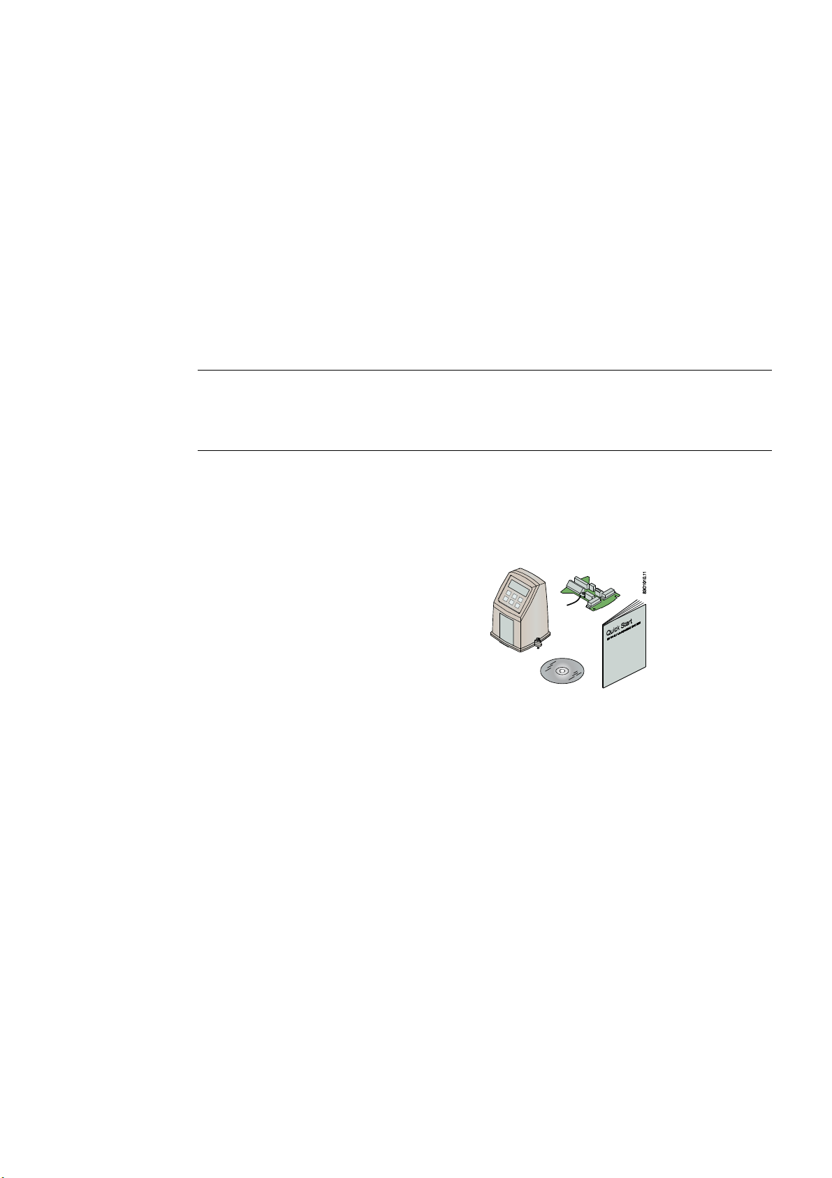
1.2 Items supplied
maintenance engineers.
Note
It is the responsibility of the customer that the instructions and directions provided in the
manual are read, understood and followed by the relevant personnel before installing the
device.
• SITRANS F M MAG 5000/6000
transmitter
• Calibration report
• SITRANS F literature CD
• Quick start guide
1
Inspection
1. Check for mechanical damage due to possible improper handling during shipment. All
claims for damage are to be made promptly to the shipper.
2. Make sure the scope of delivery, and the information on the type plate corresponds to the
ordering information
SITRANS F M MAG 5000/6000
Operating Instructions, 01/2010, SFIDK.PS.026.G1.02
7
Introduction
83G1121.10
SITRANS F M MAGFLO
MAG 6000
Maximum teghtening torque 4 ft-lb
No direct sunlight exposure
Class 1, Division 2, Group A, B, C, D
Code no.:
Supply:
IP:
Tamb.:
7ME6920-1AA10-1AA0
115/230V AC 50-60Hz 17VA
67 / NEMA 6
-20° to +60° C
1.3 History
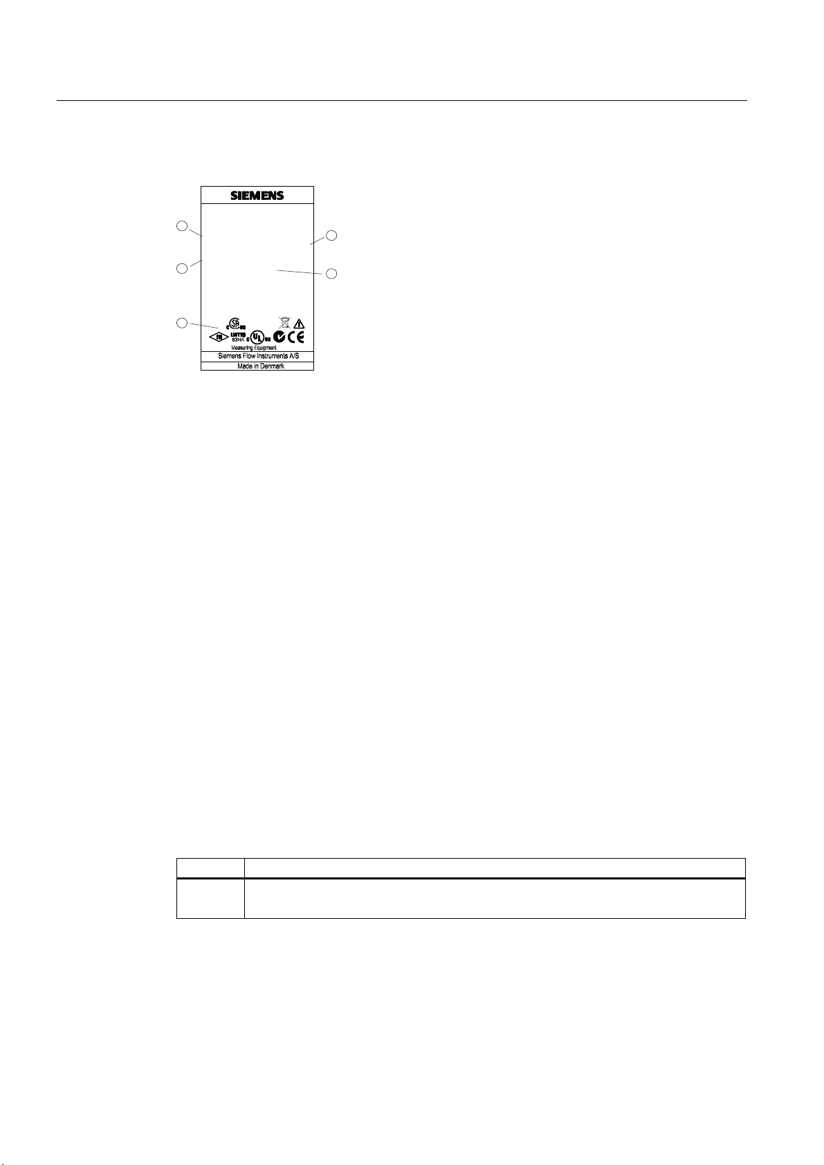
Device identification
1
3
5
① Code number
② Power supply
③ Enclosure rating
④ Ambient temperature
⑤ Approvals
Figure 1-1 MAG 5000/6000 type plate
1.3 History
This document describes:
● SITRANS F MAG 5000 and MAG 6000 transmitters (standard version).
SITRANS F M MAGFLO
MAG 6000
Code no.:
7ME6920-1AA10-1AA0
Supply:
115/230V AC 50-60Hz 17VA
IP:
67 / NEMA 6
Tamb.:
-20° to +60° C
Maximum teghtening torque 4 ft-lb
No direct sunlight exposure
Class 1, Division 2, Group A, B, C, D
83G1121.10
2
4
● Optional versions:
– MAG 5000 Blind and MAG 6000 Blind
– MAG 5000 CT and MAG 6000 CT
– MAG 6000 SV
Documentation history
The contents of these instructions are regularly reviewed and corrections are included in
subsequent editions. We welcome all suggestions for improvement.
The following table shows the most important changes in the documentation compared to
each previous edition.
Edition Remarks
01
01/2010
SITRANS F M MAG 5000/6000
8 Operating Instructions, 01/2010, SFIDK.PS.026.G1.02
First edition

Introduction
1.4 Further Information
1.4 Further Information
The contents of these Operating Instructions shall not become part of or modify any prior or
existing agreement, commitment or legal relationship. All obligations on the part of Siemens
AG are contained in the respective sales contract which also contains the complete and
solely applicable warranty conditions. Any statements contained herein do not create new
warranties or modify the existing warranty.
Product information on the Internet
The Operating Instructions are available on the CD-ROM shipped with the device, and on
the Internet on the Siemens homepage, where further information on the range of SITRANS
F flowmeters may also be found:
Product information on the internet (http://www.siemens.com/flowdocumentation
Worldwide contact person
If you need more information or have particular problems not covered sufficiently by the
operating instructions, please get in touch with your contact person. You can find contact
information for your local contact person on the Internet:
Local contact person (http://www.automation.siemens.com/partner
)
)
SITRANS F M MAG 5000/6000
Operating Instructions, 01/2010, SFIDK.PS.026.G1.02
9

Introduction
1.4 Further Information
SITRANS F M MAG 5000/6000
10 Operating Instructions, 01/2010, SFIDK.PS.026.G1.02

Safety notes
2.1 Laws and directives
General requirements
CAUTION
Correct, reliable operation of the product requires proper transport, storage, positioning and
assembly as well as careful operation and maintenance. Only qualified personnel should
install or operate this instrument.
Note
Alterations to the product, including opening or improper repairs of the product, are not
permitted.
If this requirement is not observed, the CE mark and the manufacturer's warranty will expire.
Installation of the equipment must comply with national regulations. For example EN 6007914 for the European Community.
2
Instrument safety standards
The device has been tested at the factory, based on the safety requirements. In order to
maintain this condition over the expected life of the device the requirements described in
these Operating Instructions must be observed.
CE marked equipment
The CE-mark symbolizes the compliance of the device with the following guidelines:
● EMC-guideline 89/336/EEC
● Low voltage guideline 73/23/EWG
● ATEX Directive 94/9/EG
● CT: (MI-001) Directive 2004/22/EC
SITRANS F M MAG 5000/6000
Operating Instructions, 01/2010, SFIDK.PS.026.G1.02
11

Safety notes
2.2 Installation in hazardous location
2.2 Installation in hazardous location
WARNING
Equipment used in hazardous areas must be Ex-approved and marked accordingly. It is
required that the special conditions for safe use provided in the manual and in the Ex
certificate are followed!
Ex approvals
CSA Class I, Division 2, Groups A, B, C and D. Code T5 for an ambient temperature of
+60ºC.
FM Class I, Division 2, Groups A, B, C and D and Class I, Zone 2, Group IIC indoor/outdoor
Type IP67 hazardous (classified) locations
Temperature specifications for Ex use
Temperature class Ambient temperature [°C]
-40...+40 -40...+50 -40...+60
T2 180 (process temperature) - T3 165 (process temperature) 140 (process temperature) T4 100 (process temperature) 100 (process temperature) 80 (process temperature)
T5 65 (process temperature) 65 (process temperature) 65 (process temperature)
T6 50 (process temperature) 50 (process temperature) 50 (process temperature)
EX requirements
It is required that:
● Electrical connections are in accordance with Elex V (VO in explosion hazardous areas)
and EN60079-14 (Installing Electrical Systems in Explosion Hazardous Areas).
● The protective cover over the power supply is properly installed. For intrinsically safe
circuits the connection area can be opened.
● Appropriate cable connectors are used for the output cicuits: intrinsically safe: blue, nonintrinsically safe: black
● Sensor and transmitter are connected to the potential equalization. For intrinsically safe
output circuits potential equalization must be maintained along the entire connection path.
● Sensor insulation thickness is max. 100mm (only insulated sensors).
● EN50281-1-2 is considered for installation in areas with combustible dust.
● When protective earth (PE) is connected, no potential difference between the protective
earth (PE) and the potential equalization (PA) can exist, even during a fault condition.
SITRANS F M MAG 5000/6000
12 Operating Instructions, 01/2010, SFIDK.PS.026.G1.02

Description
3.1 System components
A SITRANS F M MAG 5000/6000 flowmeter system includes:
● Transmitter (type SITRANS F M MAG 5000/6000)
● Sensor (types: SITRANS F MAG 1100/1100F/3100/3100 P/5100 W)
● Communication module (optional) (types: HART, PROFIBUS PA/DP, MODBUS RTU RS
485, Foundation Fieldbus H1, Devicenet)
● SENSORPROM memory unit
Communication solutions
The SITRANS F USM II range of add on modules, presently including HART, Foundation
Fieldbus. MODBUS RTU RS 485, PROFIBUS PA / DP and Devicenet, are all applicable with
the SITRANS F M MAG 6000 transmitter.
3.2 Operating principle
3
The transmitters are microprocessor-based with a built-in alphanumeric display in several
languages. The flow measuring principle is based on Faraday's law of electromagnetic
induction. Magnet coils mounted diametrically on the measuring pipe generate a pulsed
electromagnetic field. The liquid flowing through this electromagnetic field induces a voltage.
The transmitters evaluate the signals from the associated electromagnetic sensors, convert
the signals into appropriate standard signals such as 4 ... 20 mA, and also fulfil the task of a
power supply unit providing the magnet coils with a constant current.
The transmitter consists of a number of function blocks which convert the sensor voltage into
flow readings.
3.3 Applications
The DC-powered magnetic flowmeters are suitable for measuring the flow of almost all
electrically conductive liquids, pastes, and slurries with max. 40% solids. The main
applications can be found in the following sectors:
● Water and waste water
● Chemical and pharmaceutical industries
● Food & beverage industry
● Mining, aggregates and cements industries
● Pulp and paper industry
● Steel industry
● Power generation; utility and chilled water industry
SITRANS F M MAG 5000/6000
Operating Instructions, 01/2010, SFIDK.PS.026.G1.02
13

Description
3.4 Features
3.4 Features
Power supply
2 different types of power supply are available. A 12 ... 24 V AC/DC and a 115 ... 230 V AC
switch mode type.
Coil current module generates a pulsating magnetizing current that drives the coils in the
sensor. The current is permanently monitored and corrected. Errors or cable faults are
registered by the self-monitoring circuit.
Input circuit amplifies the flow-proportional signal from the electrodes. The input impedance
is extremely high: >10
low as 5 µS/cm. Measuring errors due to cable capacitance are eliminated due to active
cable screening.
Digital signal processor converts the analog flow signal to a digital signal and suppresses
electrode noise through a digital filter. Inaccuracies in the transmitter as a result of long-term
drift and temperature drift are monitored and continuously compensated for via the selfmonitoring circuit. The analog to digital conversion takes place in an ultra low noise ASIC
with 23 bit signal resolution. This has eliminated the need for range switching. The dynamic
range of the transmitter is therefore unsurpassed with a turn down ratio of minimum 3000:1.
CAN communication
The transmitter operates internally via an internal CAN communication bus. Signals are
transferred through a signal conditioner to the display module and to/from internal/external
option modules and the dialog module.
Dialog module
The display unit consists of a 3-line display and a 6-key keypad. The display shows a flow
rate or a totalizer value as a primary reading.
Output module
The output module converts flow data to analog, digital and relay outputs. The outputs are
galvanically isolated and can be individually set to suit a particular application.
14
Ω which allows flow measurements on fluids with conductivities as
SITRANS F M MAG 5000/6000
14 Operating Instructions, 01/2010, SFIDK.PS.026.G1.02

Description
3.5 MAG 5000/MAG 6000 versions
3.5 MAG 5000/MAG 6000 versions
The transmitters are designed in various versions and offer high performance and easy
installation, commissioning and maintenance.
Standard version
The standard version is an IP67 version for compact or remote installation. Its robust design
ensures a long lifetime if installed outdoors.
Blind version
This version carries all the normal MAG 5000/6000 features, except those associated with
the display and keypad.
Both current and digital outputs are available.
Factory setting of current output in unit is switched off when delivered.
CT version
The MAG 5000/6000 CT version is a custody transfer-approved transmitter.
It is approved accordi
ng to:
● Cold water pattern approval (MAG 5000/6000 CT):
– PTB
– OIML R 49
● Cold water pattern approval (MAG 6000 CT only):
– MI-001
● Hot water pattern approval (MAG 6000 CT only):
– PTB
● Heat meter pattern approval (MAG 6000 CT only):
– OIML R 75
● Other media than water (MAG 6000 CT only):
– OIML R 117
SV version (MAG 6000 only)
This version is identical to the standard MAG 6000 transmitters except for the following
additional functions:
● Zero point adjustment
● Adjustable excitation frequency up to 44 Hz
SITRANS F M MAG 5000/6000
Operating Instructions, 01/2010, SFIDK.PS.026.G1.02
15

Description
3.5 MAG 5000/MAG 6000 versions
SITRANS F M MAG 5000/6000
16 Operating Instructions, 01/2010, SFIDK.PS.026.G1.02
Installing/Mounting
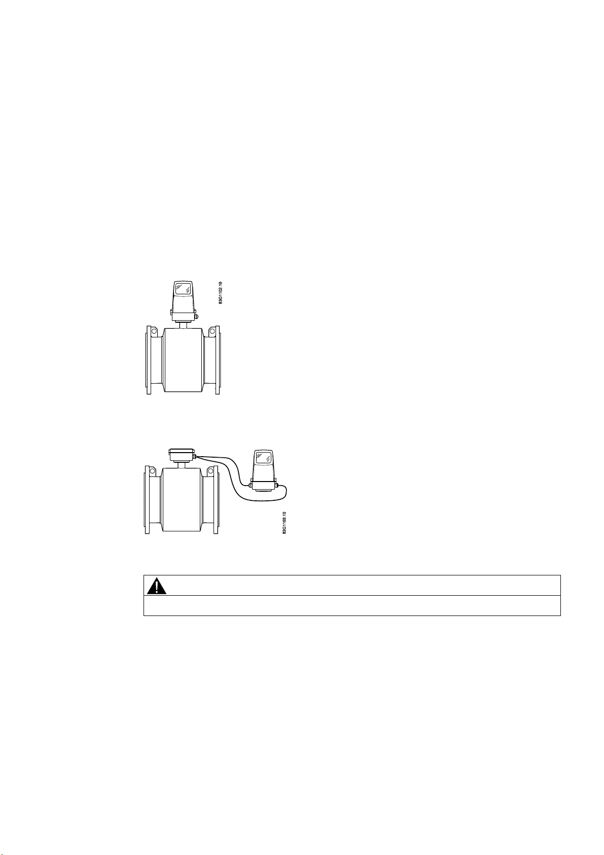
This chapter describes how to install the flowmeter in the compact version as well as in the
remote version.
The transmitter is delivered ready for mounting on the sensor. The transmitter is delivered
with a compression plate ready for mounting on the sensor. No further assembling is
necessary.
The transmitter can be installed either compact on the sensor or remote.
Figure 4-1 Compact installation
4
Figure 4-2 Remote installation
CAUTION
See Cable requirements (Page 68) before installing transmitter
SITRANS F M MAG 5000/6000
Operating Instructions, 01/2010, SFIDK.PS.026.G1.02
17
Installing/Mounting
4.1 Installation conditions
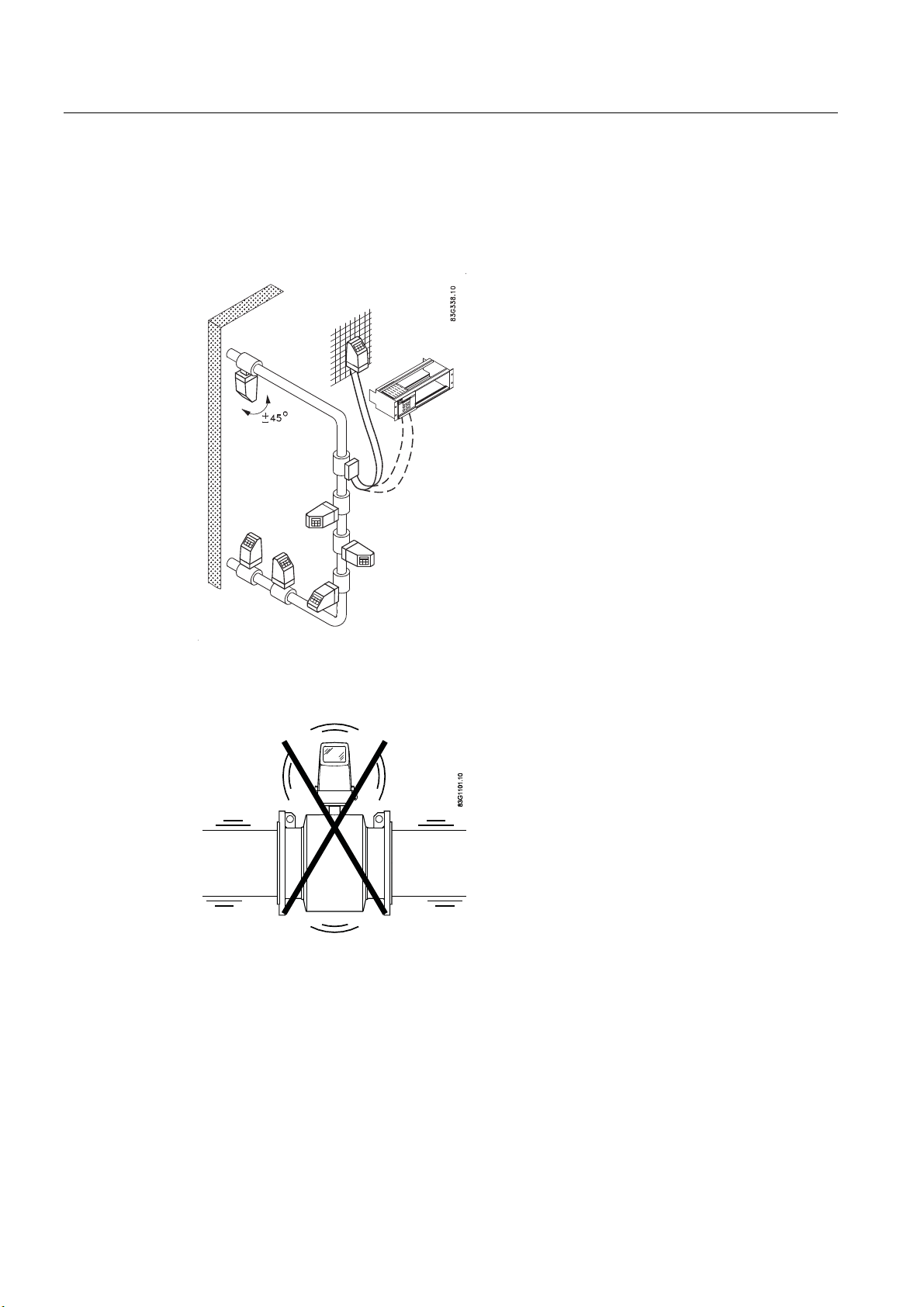
4.1 Installation conditions
Reading and operating the flowmeter is possible under almost any installation conditions
because the display can be oriented in relation to the sensor. To ensure optimum flow
measurement, attention should be paid to the following:
Vibrations
Figure 4-3 Avoid strong vibrations
SITRANS F M MAG 5000/6000
18 Operating Instructions, 01/2010, SFIDK.PS.026.G1.02
Installing/Mounting
4.1 Installation conditions
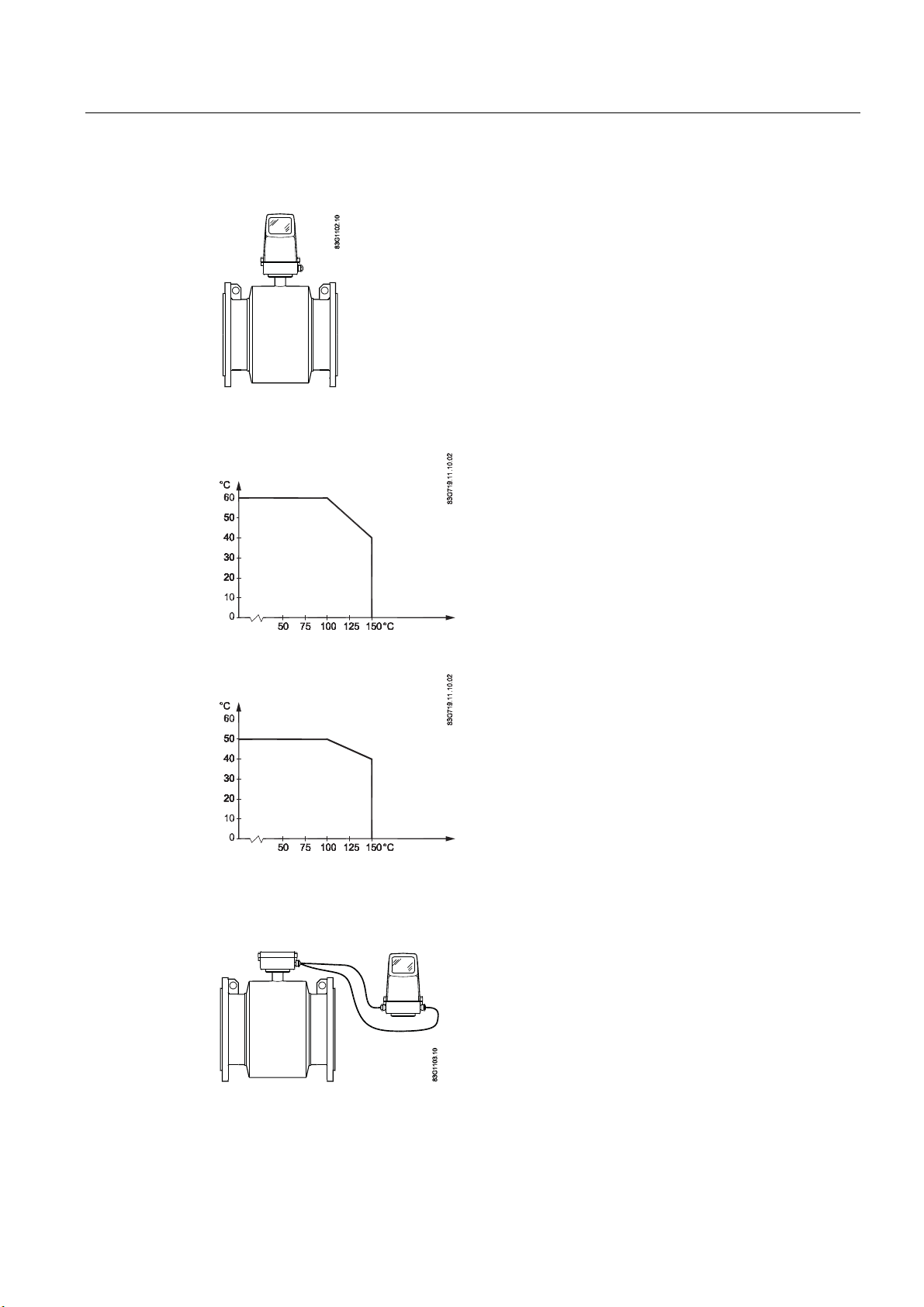
Compact installation
Medium temperature must be in accordance with the graphs showing max. ambient
temperature as a function of medium temperature.
$PELHQWWHPSHUDWXUH
Figure 4-4 Standard, blind and SV versions
$PELHQWWHPSHUDWXUH
Figure 4-5 CT version
Remote installation
0HGLXP
WHPSHUDWXUH
0HGLXP
WHPSHUDWXUH
Cable length and type (as described in Cable requirements) must be used.
For installation conditions for sensors, see respective sensor operating instructions.
SITRANS F M MAG 5000/6000
Operating Instructions, 01/2010, SFIDK.PS.026.G1.02
19
Installing/Mounting
4.2 MAG 5000/6000 compact
4.2 MAG 5000/6000 compact
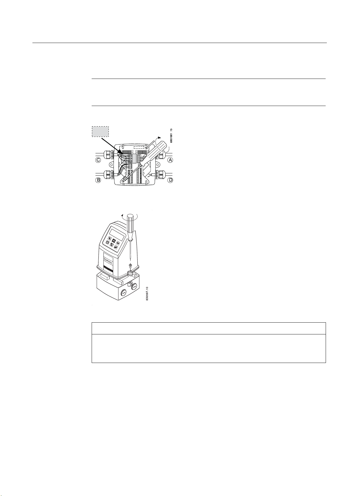
Install MAG 5000 / MAG 6000 compact version
1. Remove and discard terminal box lid of sensor.
2. Ensure SENSORPROM
3. Fit M20 or ½" NPT cable glands for supply and output cables.
®
memory unit is installed.
4. Unplug the two black plug assemblies for coil and electrode cables in terminal box.
5. Connect earth wire from connection board to bottom of terminal box.
6. Connect 2-pin connector and 3-pin connector as shown to their corresponding terminal
numbers on connection board as shown in Electrical connection (Page 34).
Note
System will not register flow if black plugs are not connected to connection board
A
7. Fit supply and output cables through cable glands and connect to connection plate as
shown in Electrical connection (Page 34).
SITRANS F M MAG 5000/6000
20 Operating Instructions, 01/2010, SFIDK.PS.026.G1.02
Installing/Mounting
4.2 MAG 5000/6000 compact
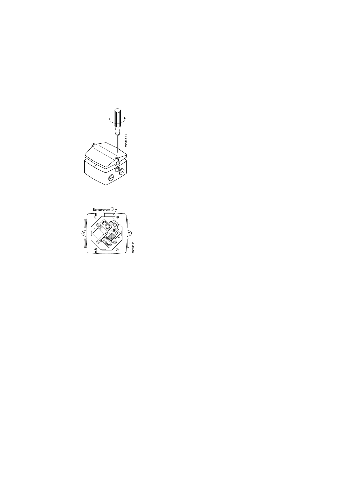
8. Mount connection plate in terminal box.
Note
Check that your connection board lines up with SENSORPROM
®
SENSORPROM
unit to the other side of terminal box.
®
unit, if not, move
SENSORPROM® memory unit connections will be established automatically when
connection plate is mounted in terminal box.
B
9. Tighten cable glands to obtain optimum sealing.
10. Mount transmitter on terminal box.
11. Transmitter is ready to be powered up.
CAUTION
Exposing transmitter to direct sunlight may increase operating temperature above its
specified limit, and decrease display visibility.
A sunshield is available as accessory.
SITRANS F M MAG 5000/6000
Operating Instructions, 01/2010, SFIDK.PS.026.G1.02
21
Installing/Mounting
4.3 Remote installation
4.3 Remote installation
At sensor
1. Remove terminal box lid.
2. Remove SENSORPROM
wall mounting unit.
®
unit from sensor terminal box and mount it in terminal box of
3. Fit M20 or ½" NPT cable glands for cables.
SITRANS F M MAG 5000/6000
22 Operating Instructions, 01/2010, SFIDK.PS.026.G1.02
Installing/Mounting
4.3 Remote installation
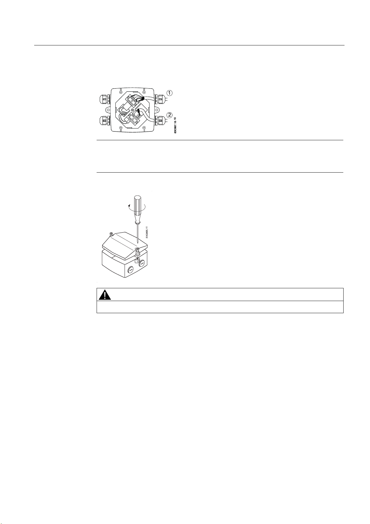
4. Fit and connect electrode (1) and coil (2) cables as shown in Electrical connection
(Page 34).
Note
Unscreened cable ends must be kept as short as possible.
Electrode cable and coil cable must be kept separate to prevent interference.
5. Tighten cable glands well to obtain optimum sealing.
WARNING
Mount terminal box lid before power up.
SITRANS F M MAG 5000/6000
Operating Instructions, 01/2010, SFIDK.PS.026.G1.02
23
Installing/Mounting
4.3 Remote installation
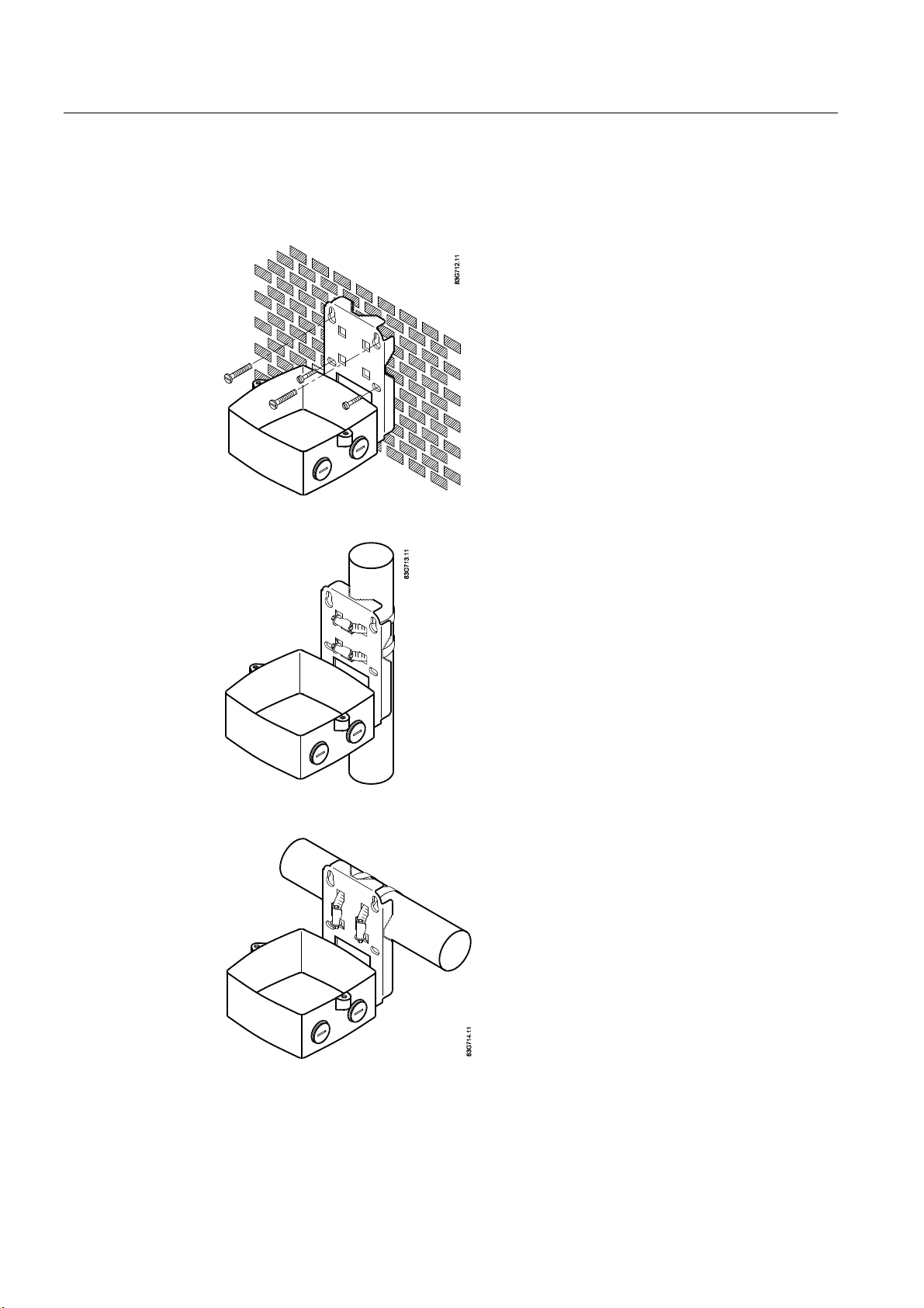
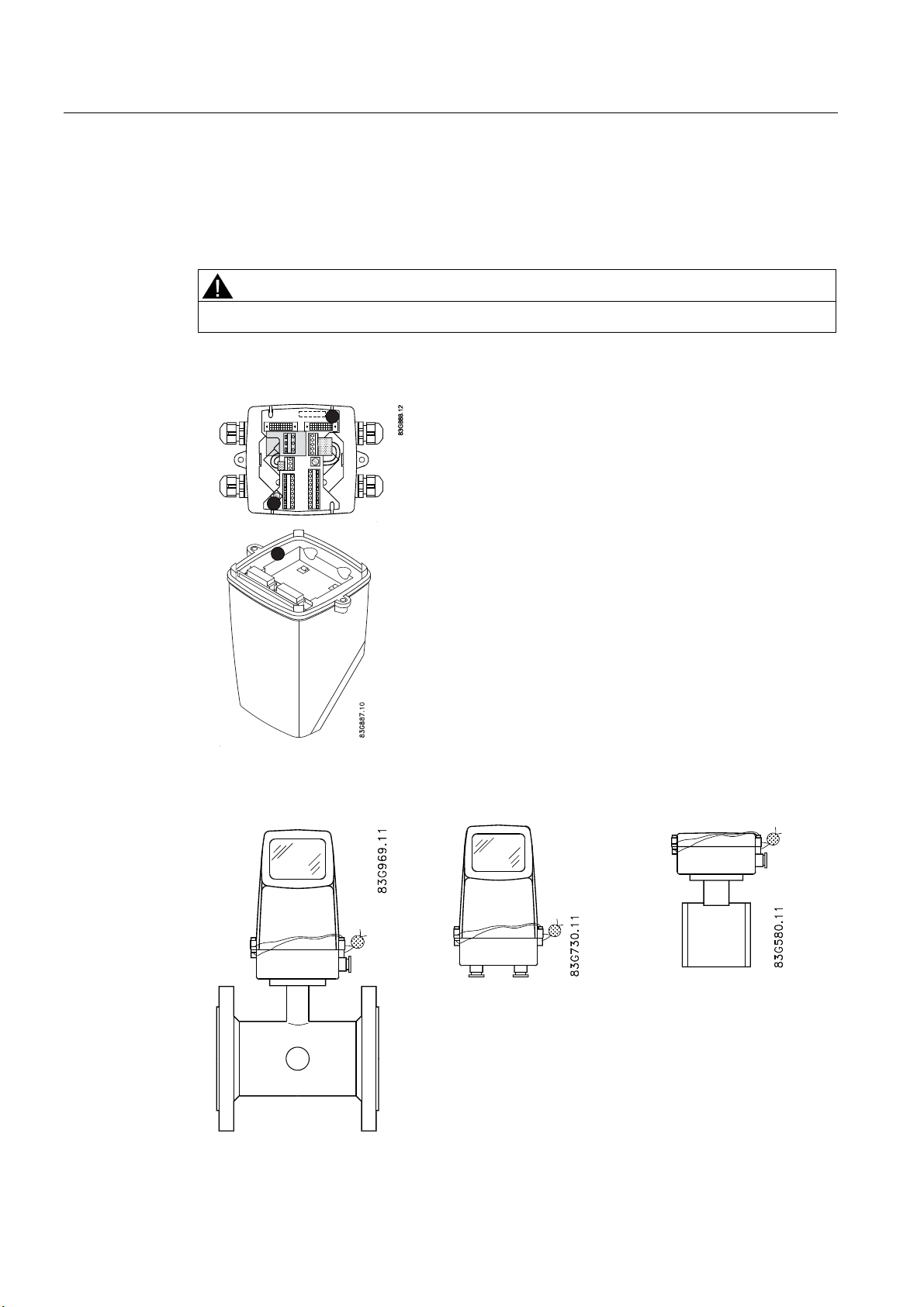
Wall mounting
1. Mount bracket on a wall or on a horizontal or a vertical pipe using ordinary hose clips or
duct straps.
Figure 4-6 Wall mounting
Figure 4-7 Pipe mounting - vertical
Figure 4-8 Pipe mounting - horizontal
2. Ensure that correct SENSORPROM® memory unit is mounted in wall/pipe mounting unit.
3. Fit M20 or ½" NPT cable glands for cables from bottom or sides of terminal box.
SITRANS F M MAG 5000/6000
24 Operating Instructions, 01/2010, SFIDK.PS.026.G1.02
Installing/Mounting
4.3 Remote installation
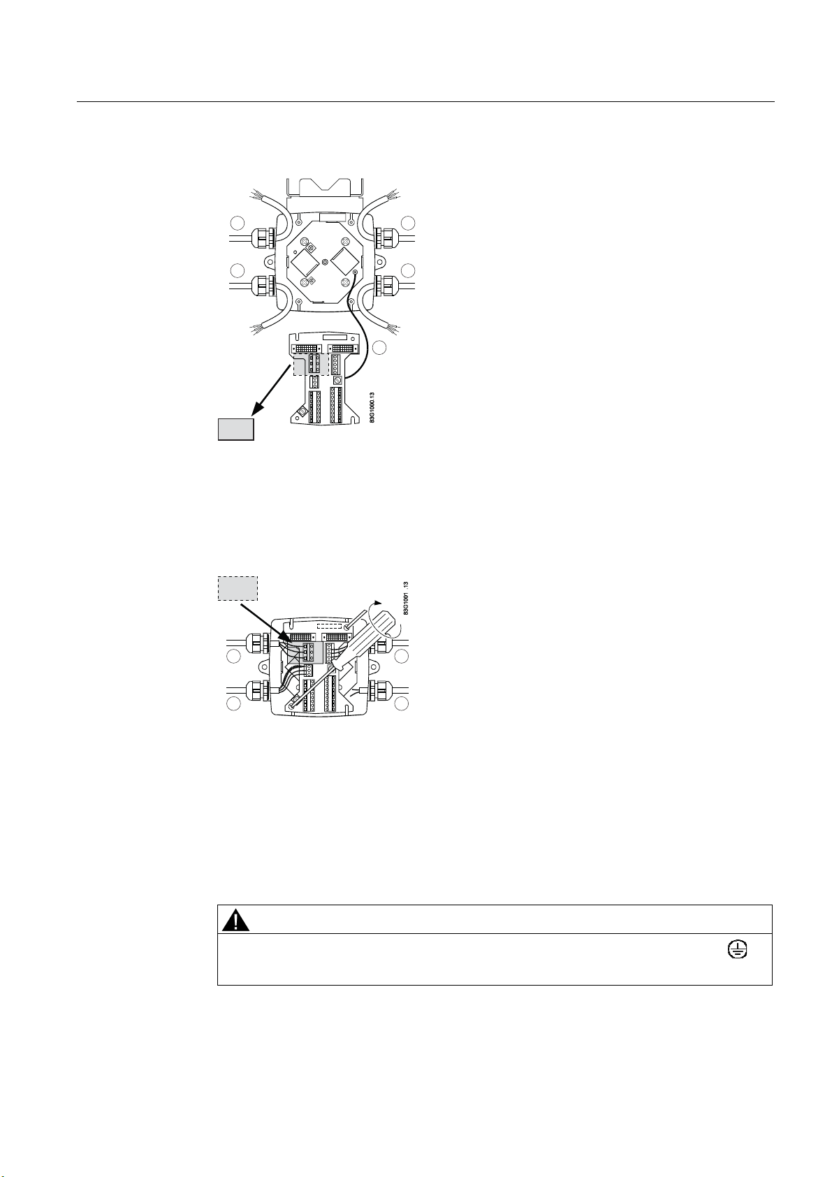
4. Mount earth wire in bottom of terminal box.
3
2
1
4
5
1 Connect electrode cable
2 Connect coil cable - keep separate from electrode cable
3 Connect power supply
4 Connect output cable
5 Connect PE (ground) wire
1. Mount connection plate in terminal box.
B
3
2
1
4
1 Electrode cable
2 Coil cable
3 Power supply
4 Output cable
1. Fit coil, electrode, supply and output cables through cable glands and connect to
connection plate as shown in Electrical connection (Page 34).
2. Fix conne
ction plate with the two diagonally opposite screws.
3. Tighten cable glands to obtain optimum sealing.
CAUTION
When remote mounted, power supply PE wire must be connected to PE terminal ( ).
Coil cable shield must be connected to SHIELD terminal.
SITRANS F M MAG 5000/6000
Operating Instructions, 01/2010, SFIDK.PS.026.G1.02
25
Installing/Mounting
4.3 Remote installation
4. Mount transmitter on terminal box.
5. Transmitter is ready to be powered up.
CAUTION
Exposing the transmitter to direct sunlight may increase the operating temperature
above its specified limit, and decrease display visibility.
A sun shield is available as accessory.
SITRANS F M MAG 5000/6000
26 Operating Instructions, 01/2010, SFIDK.PS.026.G1.02
Installing/Mounting
4.4 MAG 5000/6000 CT
4.4 MAG 5000/6000 CT
To ensure that the settings of this custody transfer-approved MAG 5000/6000 CT transmitter
are not changed, it is necessary to install a hardware key to lock the software functions and
to seal the device.
MAG 6000 CT is installed like a Standard MAG 6000 except for the final sealing.
Calibration sealing has been carried out at calibration.
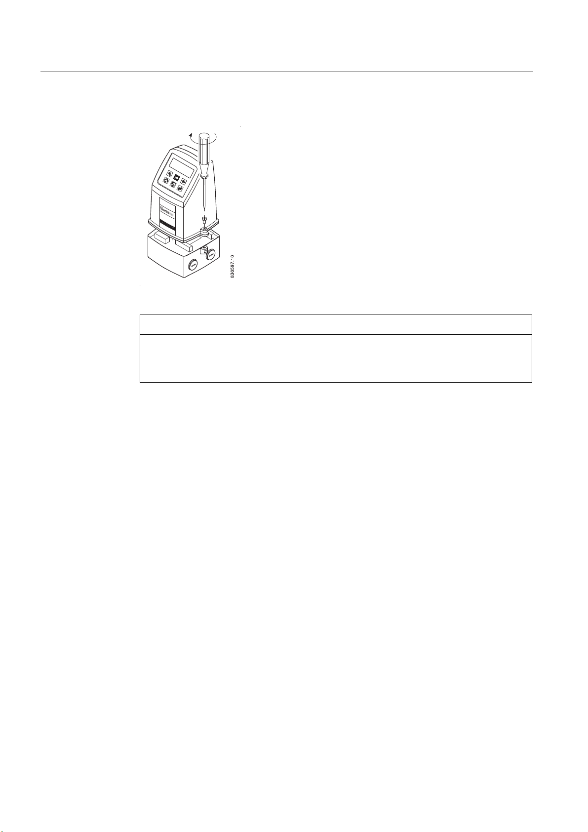
4.4.1 Installing hardware key
Use hardware key on non-verified transmitter
1. Mount hardware key on transmitter connection plate during setting of primary operating
parameters such as Q
commissioning or calibration. See setup menus in appendix menu diagrams (Page 73).
., low-flow cut-off, units, approvals, etc. in connection with
max
2. Remove hardware key after setting up and calibrating unit.
This locks the menu structure and the selected settings.
Note
Hardware key function
Setting of primary operating parameters is blocked during normal operation.
When key is mounted, access to all menu items is gained. When key is removed, primary
settings are blocked in accordance with requirements in authorisation.
SITRANS F M MAG 5000/6000
Operating Instructions, 01/2010, SFIDK.PS.026.G1.02
27
Installing/Mounting
4.4 MAG 5000/6000 CT
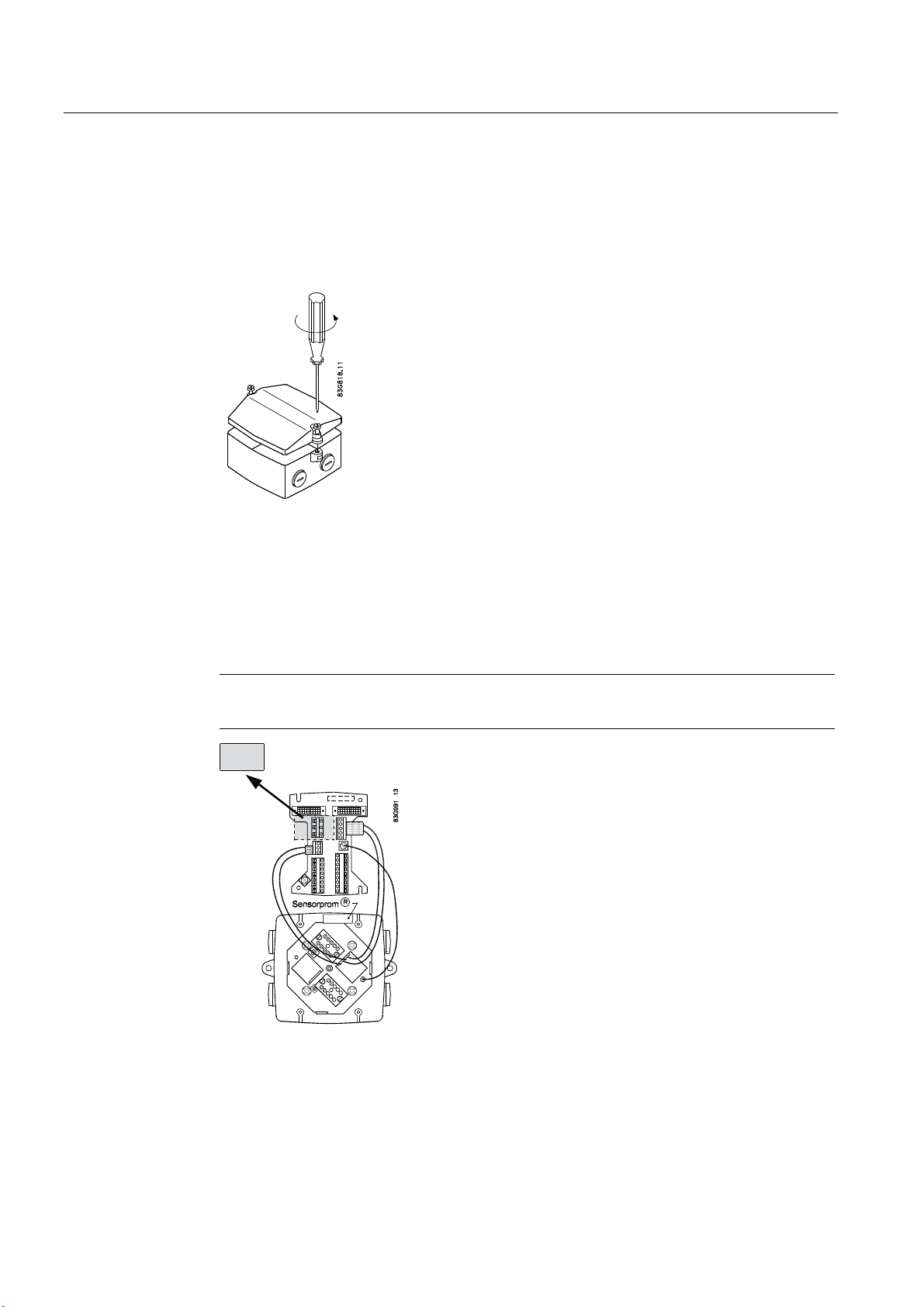
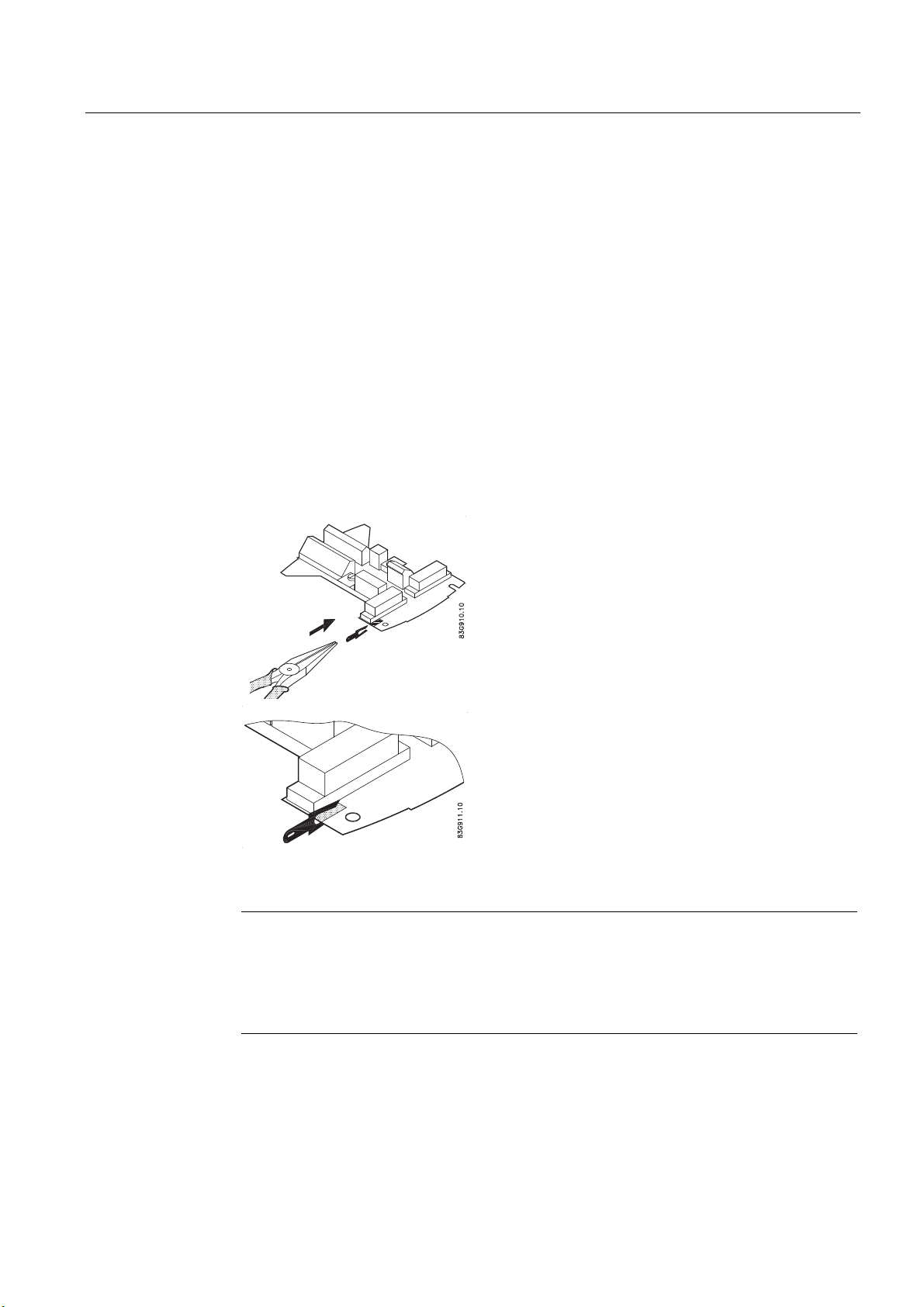
4.4.2 Seal device
Seal transmitter
CAUTION
Seal transmitter to prevent unauthorized access.
1. Seal connection plate to prevent access to SENSORPROM® memory unit as shown
below. 1 indicates sealing locations.
1
1
1
2. Drill through marked drilling holes in terminal box and transmitter/lid. Seal transmitter
externally as shown below.
SITRANS F M MAG 5000/6000
28 Operating Instructions, 01/2010, SFIDK.PS.026.G1.02
 Loading...