

Siemens SITRANS F M MAG 3100 Operating Instructions Manual
SITRANS F
Electromagnetic flowmeters
SITRANS F M MAG 3100
Operating Instructions • 06/2010
SITRANS F


1
Introduction
2
Safety notes
3
Description
SITRANS F
4
Installing/Mounting
Electromagnetic Flowmeters
SITRANS F M MAG 3100
5
Connecting
6
Service and maintenance
Operating Instructions
7
Troubleshooting/FAQs
8
Technical data
A
Appendix
Electromagnetic flow sensor designed for use with
transmitter types SITRANS F M MAG 5000 / 6000 and
MAG 6000 I
06/2010
A5E03005599-01

Legal information
Warning notice system
This manual contains notices you have to observe in order to ensure your personal safety, as well as to prevent
damage to property. The notices referring to your personal safety are highlighted in the manual by a safety alert
symbol, notices referring only to property damage have no safety alert symbol. These notices shown below are
graded according to the degree of danger.
DANGER
indicates that death or severe personal injury will result if proper precautions are not taken.
WARNING
indicates that death or severe personal injury may result if proper precautions are not taken.
CAUTION
with a safety alert symbol, indicates that minor personal injury can result if proper precautions are not taken.
CAUTION
without a safety alert symbol, indicates that property damage can result if proper precautions are not taken.
NOTICE
indicates that an unintended result or situation can occur if the corresponding information is not taken into
account.
If more than one degree of danger is present, the warning notice representing the highest degree of danger will
be used. A notice warning of injury to persons with a safety alert symbol may also include a warning relating to
property damage.
Qualified Personnel
The product/system described in this documentation may be operated only by personnel qualified for the specific
task in accordance with the relevant documentation for the specific task, in particular its warning notices and
safety instructions. Qualified personnel are those who, based on their training and experience, are capable of
identifying risks and avoiding potential hazards when working with these products/systems.
Proper use of Siemens products
Note the following:
WARNING
Siemens products may only be used for the applications described in the catalog and in the relevant technical
documentation. If products and components from other manufacturers are used, these must be recommended
or approved by Siemens. Proper transport, storage, installation, assembly, commissioning, operation and
maintenance are required to ensure that the products operate safely and without any problems. The permissible
ambient conditions must be adhered to. The information in the relevant documentation must be observed.
Trademarks
All names identified by ® are registered trademarks of the Siemens AG. The remaining trademarks in this
publication may be trademarks whose use by third parties for their own purposes could violate the rights of the
owner.
Disclaimer of Liability
We have reviewed the contents of this publication to ensure consistency with the hardware and software
described. Since variance cannot be precluded entirely, we cannot guarantee full consistency. However, the
information in this publication is reviewed regularly and any necessary corrections are included in subsequent
editions.
Siemens AG order number: A5E03005599 Copyright © Siemens AG 2010.
Industry Sector Ⓟ 11/2010 Technical data subject to change
Postfach 48 48
90026 NÜRNBERG
GERMANY

SITRANS F M MAG 3100
Operating Instructions, 06/2010, A5E03005599-01
3
Table of contents
1 Introduction................................................................................................................................................ 5
1.1 Items supplied................................................................................................................................5
1.2 History............................................................................................................................................6
1.3 Further Information ........................................................................................................................7
2 Safety notes............................................................................................................................................... 9
2.1 Laws and directives .......................................................................................................................9
2.2 Installation in hazardous area......................................................................................................11
2.3 Certificates ...................................................................................................................................15
3 Description............................................................................................................................................... 17
3.1 System components ....................................................................................................................17
3.2 Design..........................................................................................................................................18
3.3 Theory of operation......................................................................................................................19
4 Installing/Mounting................................................................................................................................... 21
4.1 Installation safety precautions......................................................................................................21
4.2 Determining a location .................................................................................................................22
4.3 Orienting the sensor.....................................................................................................................24
4.4 Removing the liner protectors......................................................................................................25
4.5 Mounting ......................................................................................................................................27
4.6 Potential equalization...................................................................................................................29
4.7 Installation with earthing flanges..................................................................................................31
5 Connecting .............................................................................................................................................. 33
5.1 General safety requirements........................................................................................................33
5.2 Remote installation ......................................................................................................................35
5.3 Installation check .........................................................................................................................37
5.4 Potting..........................................................................................................................................37
6 Service and maintenance ........................................................................................................................ 39
6.1
Maintenance.................................................................................................................................39
6.2 Recalibration ................................................................................................................................39
6.3 Transportation/storage.................................................................................................................39
6.4 Unit repair.....................................................................................................................................40
6.5 Technical support.........................................................................................................................40
6.6 Return procedures .......................................................................................................................41

Table of contents
SITRANS F M MAG 3100
4 Operating Instructions, 06/2010, A5E03005599-01
7 Troubleshooting/FAQs............................................................................................................................. 43
7.1 Sensor check .............................................................................................................................. 43
7.2 Fluctuating process values.......................................................................................................... 45
8 Technical data ......................................................................................................................................... 47
8.1 Cable data................................................................................................................................... 53
8.2 Pressure / temperature range ..................................................................................................... 54
8.3 Process fluid conductivity............................................................................................................ 55
8.4 Liner selection ............................................................................................................................. 56
8.5 Electrode selection...................................................................................................................... 57
8.6 Dimensions and weight............................................................................................................... 58
A Appendix.................................................................................................................................................. 63
A.1 Flange mating dimensions (metric)............................................................................................. 63
A.2 Factory settings........................................................................................................................... 65
A.3 Coil resistance............................................................................................................................. 67
A.4 Ordering ...................................................................................................................................... 68
Glossary .................................................................................................................................................. 69
Index........................................................................................................................................................ 71

SITRANS F M MAG 3100
Operating Instructions, 06/2010, A5E03005599-01
5
Introduction
1
These instructions contain all the information you need for using the device.
The instructions are aimed at persons mechanically installing the device, connecting it
electronically, configuring the parameters and commissioning it as well as service and
maintenance engineers.
Note
It is the responsibilit
y of the customer that the instructions and directions provided in the
manual are read, understood and followed by the relevant personnel before installing the
device.
1.1 Items supplied
SITRANS F M MAG 3100
Calibration report
SITRANS F literature CD
Quick Start guide
Inspection
1. Check for mechanical damage due to possible improper handling during shipment. All
claims for damage are to be made promptly to the shipper.
2. Make sure the scope of delivery, and the information on the type plate corresponds to the
ordering information
Introduction
1.2 History
SITRANS F M MAG 3100
6 Operating Instructions, 06/2010, A5E03005599-01
Identification
6,5$$7(;;
([GHLD,%&777D5HIHUWRXVHULQVWUXFWLRQV
([,'$,37r& 3LSHWHPSHUDWXUH.
([LD7(50,1$/68L 9,L P$3L :&L Q)/L ˩+
([H7(50,1$/68L 9SN,L P$
'212723(1:+,/((1(5*,6('
/
6,75$16)00$*)/20$*([
,,*'
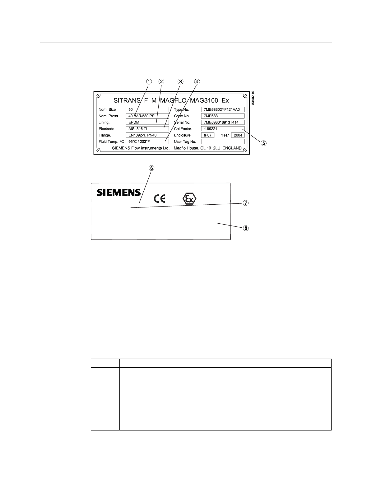
① Nominal pressure ⑤ Calibration facotr
② Liner type ⑥ Ex approval reference
③ Electrode material ⑦ Ex approval type
④ Media temperature ⑧ Intrinsical safety data
Figure 1-1 Type plate example, MAG 3100 Ex
1.2 History
The contents of these instructions are regularly reviewed and corrections are included in
subsequent editions. We welcome all suggestions for improvement.
The following table shows the most important changes in the documentation compared to
each previous edition.
Edition Remarks
01
06/2010
First edition
The Operating Instructions replaces:
MAG 3100 part of SITRANS F M HANDBOOK (A5E02435647)
MAG 3100 part of SITRANS F M MAG 6000 I Ex d Operating Instructions
MAG 3100 part of SITRANS F M MAG 6000 19" & Safety Barrier Operating
Instructions
MAG 3100 Instructions
MAG 3100 with PTFE and PFA liners Instructions

Introduction
1.3 Further Information
SITRANS F M MAG 3100
Operating Instructions, 06/2010, A5E03005599-01
7
1.3 Further Information
The contents of these Operating Instructions shall not become part of or modify any prior or
existing agreement, commitment or legal relationship. All obligations on the part of Siemens
AG are contained in the respective sales contract which also contains the complete and
solely applicable warranty conditions. Any statements contained herein do not create new
warranties or modify the existing warranty.
Product information on the Internet
The Operating Instructions are available on the CD-ROM shipped with the device, and on
the Internet on the Siemens homepage, where further information on the range of SITRANS
F flowmeters may also be found:
Product information on the internet (http://www.siemens.com/flow
)
Worldwide contact person
If you need more information or have particular problems not covered sufficiently by the
operating instructions, please get in touch with your contact person. You can find contact
information for your local contact person on the Internet:
Local contact person (http://www.automation.siemens.com/partner
)

Introduction
1.3 Further Information
SITRANS F M MAG 3100
8 Operating Instructions, 06/2010, A5E03005599-01
SITRANS F M MAG 3100
Operating Instructions, 06/2010, A5E03005599-01
9
2
Safety notes
CAUTION
Correct, reliable operation of the product requires proper transport, storage, positioning and
assembly as well as careful operation and maintenance. Only qualified personnel should
install or operate this instrument.
Note
Alterations to the product, including opening or im
proper repairs of the product, are not
permitted.
If this requirement is not observed, the CE mark and the manufacturer's warranty will expire.
2.1 Laws and directives
General requirements
Installation of the equipment must comply with national regulations. For example EN 6007914 for the European Community.
Instrument safety standards
The device has been tested at the factory, based on the safety requirements. In order to
maintain this condition over the expected life of the device the requirements described in
these Operating Instructions must be observed.
CAUTION
Material compatibility
Siemens Flow Instruments can provide assistance with the selection of wetted sensor
parts. However, the full responsibility for the selection rests with the customer and Siemens
Flow Instruments can take no responsibility for any failure due to material incompatibility.
CE marked equipment
The CE-mark symbolizes the compliance of the device with the following guidelines:
● EMC Directive 2004/108/EC
● Low Voltage Directive (LVD) 2006/95/EC
● Pressure Equipment Directive (PED/DGRL) 93/23/EG

Safety notes
2.1 Laws and directives
SITRANS F M MAG 3100
10 Operating Instructions, 06/2010, A5E03005599-01
● ATEX Directive 94/9/EC
● MID Directive 2004/22/EC
Compliance with PED directive
"Pressure Equipment Directive" (PED) is mandatory for all pressure equipment sold within
the EU and EFTA.
Siemens Flow Instruments products complies to PED as stated in the following table.
Table 2- 1 MAG 3100 PED Compliance
Flange
mm
PN 6 PN 10 PN 16 PN25 PN 40 PN 63 PN 100 150 lb 300 lb AWWA
15 N/A N/A N/A N/A EXD.PED N/A N/A N/A N/A N/A
25 N/A N/A N/A N/A EXD.PED N/A EXD.PED N/A N/A N/A
40 N/A N/A N/A N/A EXD.PED N/A PED N/A N/A N/A
50 N/A N/A N/A N/A EXD.PED PED PED N/A N/A N/A
65 EXD.PED N/A EXD.PED N/A PED PED PED N/A N/A N/A
80 EXD.PED N/A EXD.PED N/A PED PED PED N/A N/A N/A
100 EXD.PED N/A EXD.PED N/A PED PED PED N/A N/A N/A
125 EXD.PED N/A EXD.PED N/A PED PED PED N/A N/A N/A
150 EXD.PED N/A PED N/A PED PED PED N/A N/A N/A
200 EXD.PED EXD.PED PED PED PED PED PED N/A N/A N/A
250 EXD.PED EXD.PED PED PED PED PED PED N/A N/A N/A
300 EXD.PED EXD.PED PED PED PED PED PED N/A N/A N/A
350 EXD.PED EXD.PED PED PED PED N/A N/A N/A N/A N/A
400 EXD.PED EXD.PED PED PED PED N/A N/A N/A N/A N/A
450 EXD.PED EXD.PED PED PED PED N/A N/A N/A N/A N/A
500 EXD.PED EXD.PED PED PED PED N/A N/A N/A N/A N/A
600 EXD.PED EXD.PED PED PED PED N/A N/A N/A N/A N/A
700 EXD.PED EXD.PED PED* N/A N/A N/A N/A N/A N/A N/A
750 N/A N/A N/A N/A N/A N/A N/A N/A N/A N/A
800 EXD.PED EXD.PED PED* N/A N/A N/A N/A N/A N/A N/A
900 EXD.PED EXD.PED PED* N/A N/A N/A N/A N/A N/A N/A
1000 EXD.PED EXD.PED PED* N/A N/A N/A N/A N/A N/A N/A
1050 N/A N/A N/A N/A N/A N/A N/A N/A N/A N/A
1100 N/A N/A N/A N/A N/A N/A N/A N/A N/A N/A
1200 EXD.PED EXD.PED PED* N/A N/A N/A N/A N/A N/A N/A
1400 EXD.PED EXD.PED N/A* N/A N/A N/A N/A N/A N/A N/A
1500 EXD.PED EXD.PED N/A* N/A N/A N/A N/A N/A N/A N/A
1600 EXD.PED EXD.PED N/A* N/A N/A N/A N/A N/A N/A N/A
1800 EXD.PED EXD.PED N/A* N/A N/A N/A N/A N/A N/A N/A
2000 EXD.PED EXD.PED N/A* N/A N/A N/A N/A N/A N/A N/A
Safety notes
2.2 Installation in hazardous area
SITRANS F M MAG 3100
Operating Instructions, 06/2010, A5E03005599-01
11
Table 2- 2 PED table key
EXD.PED Excluded from PED under SEP or LVD
PED Product covered by PED and only available as fully PED-conforming
PED* Product covered by PED but available as either conforming or non-conforming to
PED
N/A Size/pressure outside of PED scope or not available in the size range
N/A* DN1400-2000 only avalable non conforming to PED
CAUTION
All products sold outside of EU and EFTA are excluded from the Pressure Equipment
directive, also products sold into certain market sectors are excluded. These include
1. Meters used in networks for the supply, distribution and discharge of water.
2. Meters used in pipelines for the conveyance of any fluid from offshore to onshore.
3. Meters used in the extraction of petroleum or gas, including christmas tree and manifold
equipment.
4. Any meter mounted on a ship or mobile offshore platform.
2.2 Installation in hazardous area
WARNING
Equipment used in hazardous areas must be Ex-approved and marked accordingly. It is
required that the special conditions for safe use provided in the manual and in the Ex
certificate are followed!
Hazardous area approvals
The device is approved for use in hazardous area and has the following approvals:
MAG 3100 Ex DN 350-2000:
● II 2 GD Ex e ia IIC T3-T6 (MAG 3100 Ex remote mounted)
● II 2 (1) (2) GD Ex de [ia] ia [ib] IIC T3-T6 (MAG 3100 Ex compact mounted with MAG
6000 I Ex de)

Safety notes
2.2 Installation in hazardous area
SITRANS F M MAG 3100
12 Operating Instructions, 06/2010, A5E03005599-01
MAG 3100 Ex DN 15-300
● II 2 (1) GD Ex d e ia IIC T3-T6 (MAG 3100 Ex remote mounted)
● II 2 (1)(2) GD Ex de [ia] [ib] ia IIC T3-T6 (MAG 3100 Ex compact mounted with MAG 6000
I Ex de)
WARNING
Make sure the hazardous area approval is suitable for the enviro
nment in which the
device will be installed.
WARNING
All approvals are based on non-fla
mmable processes only!
Intrinsically safe data
Table 2- 3 Intrinsically safe data for MAG 3100 Ex remote mounted
Electrode circuit "ia" (Terminal 82,83)
Ui 30V
Li 2μH
Ii 50mA
Pi 0.5W
Ci 50nF
Coil circuit "Ex e" (Terminal 85,86)
Ui 30/70V
Ii 130mA
WARNING
Compact mounted versions
For intrinsically safe data for MAG 3100 Ex compact mounted with MAG 6000 I Ex d, refer
to the Operating Instructions of MAG 6000 I or to certificate number Sira 07ATEX1182X,
available here: Certificates (http://www.siemens.com/processinst
rumentation/certificates).
WARNING
With intrinsically safe circuits, use only certified meters appropriate for the transmitter.
If a non-conforming supply unit is used, the "fail-safe" type of protection will no longer be
effective and the approval certification will be invalid.

Safety notes
2.2 Installation in hazardous area
SITRANS F M MAG 3100
Operating Instructions, 06/2010, A5E03005599-01
13
Temperature specifications for Ex use
Table 2- 4 Temperature specifications for MAG 3100 Ex
Temperature class Maximum process fluid temperature
[°C]
Ambient temperature [°C]
T3 180 -20 ... +50
T4 122 -20 ... +60
T5 87 -20 ... +60
T6 72 -20 ... +60
For dust protection, the surface temperature is equal to the process fluid temperature plus 5°C
Special conditions for safe use
It is required that:
● Electrical connections are in accordance with EN60079-14 (Installing Electrical Systems
in Explosion Hazardous Areas).
● Appropriate cable connectors are used for the output circuits:
– Intrinsically safe: blue
– Non-intrinsically safe: black
Safety notes
2.2 Installation in hazardous area
SITRANS F M MAG 3100
14 Operating Instructions, 06/2010, A5E03005599-01
● Sensor insulation thickness is max. 100mm (only insulated sensors).
● IEC/EN 61241-14 and 61241-17 are considered for installation in areas with combustible
dust.
WARNING
Potential equalization
In operation, the output is earthed through the conductive medium b
eing measured and
therefore potential equalisation is necessary throughout the hazardous area.
The apparatus housing shall be connected to the potential equalising conductor in the
hazardous area.
WARNING
External connections to Ex e terminals
The ext
ernal connections to the Ex 'e' Terminals of the Remote version shall comply
with the following:
The wire conductors shall have a cross-sectional area between 0.5 mm
2
and 4 mm2.
No more than one single or multiple strand wire conductor shall normally be
connected to each of the terminals. If multiple conductors are required, these shall be
joined in a suitable manner, e.g. two conductors into a single insulated crimped boot
lace ferrule.
The insulation on the wire conductors shall extend to within 1mm of the metal of the
terminal throat.
The terminal screws shall be tightened down with a torque between 0.5 Nm and 0.7
Nm.
The terminals shall never be exposed to temperatures outside of the range -50°C to
+ 130°C; in addition, they shall only be installed and wired with cable in an ambient
temperature of -10 to +80°C. Furthermore, in the event of there being a process
temperatures of + 180°C in conjunction with an upper ambient temperature of +50°C
the terminal strips should not be installed or wired with cable.
WARNING
Explosive gas or dust
The termin
al box shall not be opened when an explosive gas or dust atmosphere may
be present.
WARNING
"Flameproof enclosure" type of protection
Only o
pen devices with type of protection "Flameproof enclosure" in hazardous areas
when the power to the device is turned off, otherwise there is a risk of explosion.
WARNING

Safety notes
2.3 Certificates
SITRANS F M MAG 3100
Operating Instructions, 06/2010, A5E03005599-01
15
Laying of cables
Cable for use in zone 1 and 2 or 21 and 22 must satisfy the requirements for having a
proof voltage < AC 500 V applied between the conductor/ground, conductor/shield and
shield/ground.
Connect the devices that are operated in hazardous areas as per the stipulations
applicable in the country of operation, e.g. for Ex "d" and "nA", permanent cables must
be laid.
2.3 Certificates
Certificates are posted on the Internet and on the documentation CD-ROM shipped with the
device.
See also
Certificates (http://www.siemens.com/processinstrumentation/certificates)

Safety notes
2.3 Certificates
SITRANS F M MAG 3100
16 Operating Instructions, 06/2010, A5E03005599-01

SITRANS F M MAG 3100
Operating Instructions, 06/2010, A5E03005599-01
17
Description
3
The main applications of the SITRANS F M electromagnetic flow sensors can be found in the
following fields:
● Process industry
● Chemical industry
● Steel industry
● Mining
● Utility
● Power generation & distribution
● Oil & gas / HPI
● Water & waste water
● Pulp & paper
3.1 System components
The SITRANS F M USM II flowmeter system includes:
● Transmitter (types: SITRANS F M MAG 5000/6000 or MAG 6000 I)
● Sensor (types: SITRANS F M MAG 1100/1100F, MAG 3100/3100 P or MAG 5100 W)
● Communication module (optional) (types: HART, PROFIBUS PA/DP, MODBUS RTU RS
485, Foundation Fieldbus H1, Devicenet)
● SENSORPROM memory unit
Communication solutions
The SITRANS F USM II range of add on modules, presently including HART, Foundation
Fieldbus. MODBUS RTU RS 485, PROFIBUS PA / DP and Devicenet, are all applicable with
the SITRANS F M MAG 6000 transmitter.
Description
3.2 Design
SITRANS F M MAG 3100
18 Operating Instructions, 06/2010, A5E03005599-01
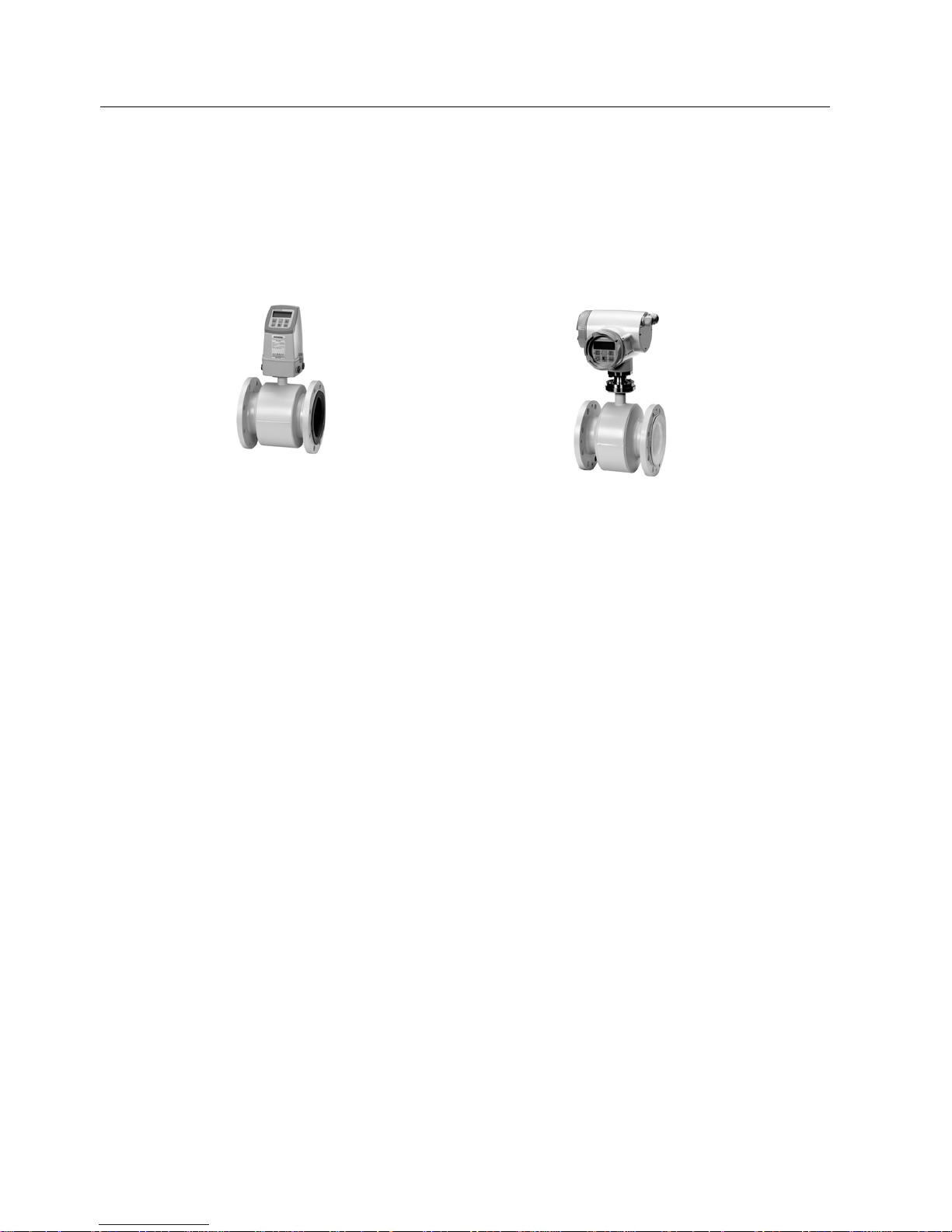
3.2 Design
SITRANS F M MAG 3100 is available in a wide range of sizes (DN 15 to DN 2000 (½" to
78")) and pressure ratings (PN 6 to PN 100 / ANSI Class 150 / 300, AS 2129 / AS 4087. On
request up to 690 bar (10 000 psi)) The fully welded construction provides a ruggedness that
suits the toughest applications and environments.
Sensor housing and flanges are designed in carbon steel (ASTM A 105) and terminal box in
fibre glass reinforced polyamide or optionally in stainless steel (AISI 316). Measuring pipe is
made of stainless steel (AISI 304) while liners and electrodes are available in various
material, which makes the sensor highly resistant to a wide range of chemicals.
The present range of liner types includes:
● PTFE
● PFA
● Neoprene
● EPDM
● Linatex
● NBR
● Hard Rubber,
● Ebonite Hard Rubber
● PDM
Electrodes are available in:
● Hastelloy C276 or C22
● AISI 316 (1.4571)
● Platinum / Iridium
● Titanium
● Tantalum
The sensors carry a wide range of approvals, see
Technical data (Page 47).
Description
3.3 Theory of operation
SITRANS F M MAG 3100
Operating Instructions, 06/2010, A5E03005599-01
19
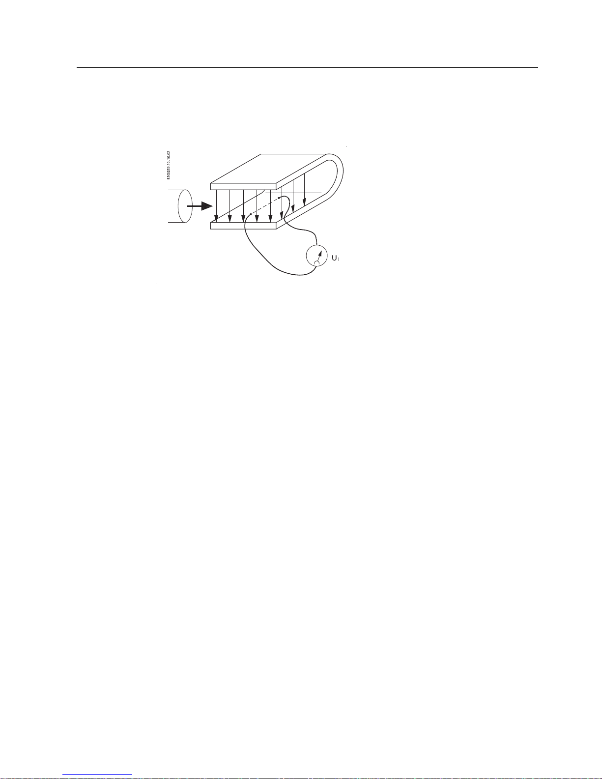
3.3 Theory of operation
The flow measuring principle is based on Faraday’s law of electromagnetic induction.
0DJQHWLF)LHOG
)ORZ
U
i
= When an electrical conductor of length L is moved at velocity v, perpendicular to the
lines of flux through a magnetic field of strength B, the voltage Ui is induced at the ends of
the conductor
U
i
= L x B x v
● Ui = Induced voltage
● L = Conductor length = Inner pipe diameter = k
1
● B = Magnetic field strength = k
2
● v = Velocity of conductor (media)
● k = k
1
x k2
Ui = k x v, the electrode signal is directly proportional to the fluid velocity
Sensorprom memory unit
All SITRANS F M electromagnetic flowmeters feature a unique SENSORPROM® memory
unit which stores sensor calibration data and transmitter settings for the lifetime of the
product.
At commissioning the flowmeter commences measurement without any initial programming.
The factory settings matching the sensor are stored in the SENSORPROM® unit. Also
customer- specified settings are downloaded to the SENSORPROM® unit. Should the
transmitter be replaced, the new transmitter will upload all previous settings and resume
measurement without any need for re-programming.
Furthermore, the "fingerprint" used in connection with the Siemens Flow Instruments
Verificator is stored during the sensor calibration.
USM II "Plug & Play" add-on communication modules
USM II - the Universal Signal Module with "Plug & Play" simplicity makes it easy to access
and integrate the flow measurement with almost any system. It ensures the flowmeter will be
easy to upgrade to new communication platforms in the future, too.

Description
3.3 Theory of operation
SITRANS F M MAG 3100
20 Operating Instructions, 06/2010, A5E03005599-01
SITRANS F M MAG 3100
Operating Instructions, 06/2010, A5E03005599-01
21
4
Installing/Mounting
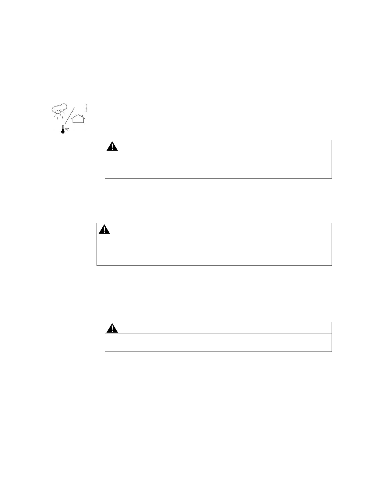
SITRANS F flowmeters
with minimum IP67/NEMA 4X enclosure rating are suitable for in-
and outdoor installations.
● Make sure that pressure and temperature specifications indicated on the device
nameplate / label will not be exceeded.
WARNING
Installation in hazardous location
Special
requirements apply to the location and interconnection of sensor and
transmitter. See "Installation in hazardous area" (Page 11)
4.1 Installation safety precautions
WARNING
In applications with working pressures/media that can be dangerous to people,
surroundings, equipment or others in case of pipe fracture, we recommend that special
precautions such as special placement, shielding or installation of a security guard or a
security valve are taken when the sensor is mounted.
● Ensure that stresses and loading caused by e.g. earthquakes, traffic, high winds and fire
damage if appropriate are taken into account during installation.
● Ensure that the flowmeter is installed such that it does not act as a focus for pipeline
stresses. External loadings are not taken into account in the flowmeter design.
● Provide adequate protection to minimise any risk of contact with hot surfaces.
WARNING
Prevent personal injuries by assurin
g that operation below pressure guards cannot take
place, if working with vacuum or fluids boiling readily.
 Loading...