

SITRANS F MAG 8000 Standard,SITRANS F MAG 8000 Irrigation,SITRANS F MAG 8000 CT,SITRANS F Series
Table of contents
 Loading...
Siemens SITRANS F MAG 8000 Standard,SITRANS F MAG 8000 Irrigation,SITRANS F MAG 8000 CT,SITRANS F Series Operating Instructions Manual

SITRANS F
Electromagnetic flowmeters
SITRANS MAG 8000
7ME6810 (MAG 8000)
7ME6820 (MAG 8000 CT)
Introduction
1
Operating Instructions
Safety notes
Description
Installing/Mounting
Connecting
Commissioning
Operation
Service and maintenance
2
3
4
5
6
7
8
Troubleshooting/FAQs
Technical data
Flow Tool
Qualification certificate
Appendix
9
10
A
B
C
11/2018
A5E03071515-AE

Legal information
Warning notice system
This manual contains notices you have to observe in order to ensure your personal safety, as well as to prevent
damage to property. The notices referring to your personal safety are highlighted in the manual by a safety alert
symbol, notices referring only to property damage have no safety alert symbol. These notices shown below are
graded according to the degree of danger.
DANGER
indicates that death or severe personal injury will result if proper precautions are not taken.
WARNING
indicates that death or severe personal injury may result if proper precautions are not taken.
CAUTION
indicates that minor personal injury can result if proper precautions are not taken.
NOTICE
indicates that property damage can result if proper precautions are not taken.
If more than one degree of danger is present, the warning notice representing the highest degree of danger will be
used. A notice warning of injury to persons with a safety alert symbol may also include a warning relating to property
damage.
Qualified Personnel
The product/system described in this documentation may be operated only by personnel qualified for the specific
task in accordance with the relevant documentation, in particular its warning notices and safety instructions. Qualified
personnel are those who, based on their training and experience, are capable of identifying risks and avoiding
potential hazards when working with these products/systems.
Proper use of Siemens products
Note the following:
WARNING
Siemens products may only be used for the applications described in the catalog and in the relevant technical
documentation. If products and components from other manufacturers are used, these must be recommended or
approved by Siemens. Proper transport, storage, installation, assembly, commissioning, operation and
maintenance are required to ensure that the products operate safely and without any problems. The permissible
ambient conditions must be complied with. The information in the relevant documentation must be observed.
Trademarks
All names identified by ® are registered trademarks of Siemens AG. The remaining trademarks in this publication
may be trademarks whose use by third parties for their own purposes could violate the rights of the owner.
Disclaimer of Liability
We have reviewed the contents of this publication to ensure consistency with the hardware and software described.
Since variance cannot be precluded entirely, we cannot guarantee full consistency. However, the information in
this publication is reviewed regularly and any necessary corrections are included in subsequent editions.
Siemens AG
Division Process Industries and Drives
Postfach 48 48
90026 NÜRNBERG
GERMANY
Document order number: A5E03071515
Ⓟ 11/2018 Subject to change
Copyright © Siemens AG 2018.
All rights reserved

Table of contents
1 Introduction...................................................................................................................................................7
1.1 Items supplied..........................................................................................................................7
1.2 History......................................................................................................................................8
1.3 Further Information...................................................................................................................8
2 Safety notes................................................................................................................................................11
2.1 General safety instructions.....................................................................................................11
2.2 Laws and directives................................................................................................................11
2.3 Conformity with European directives......................................................................................12
2.4 Lithium batteries.....................................................................................................................12
2.5 Installation in hazardous area................................................................................................12
3 Description..................................................................................................................................................13
3.1 System components...............................................................................................................13
3.2 Operating principle.................................................................................................................13
3.3 Design....................................................................................................................................13
3.4 Benefits..................................................................................................................................15
4 Installing/Mounting......................................................................................................................................17
4.1 Sensor installation..................................................................................................................18
4.1.1 Locating the sensor................................................................................................................18
4.1.2 Orienting the sensor...............................................................................................................20
4.1.3 Mounting the sensor...............................................................................................................22
4.2 Potential equalization.............................................................................................................25
4.3 Grounding..............................................................................................................................25
4.4 Cathodic-protected pipes.......................................................................................................27
4.5 Potting and direct burial.........................................................................................................28
4.6 Transmitter installation...........................................................................................................29
5 Connecting.................................................................................................................................................31
5.1 General safety requirements..................................................................................................32
5.2 Remote version......................................................................................................................33
5.3 Power supply..........................................................................................................................34
5.4 Outputs...................................................................................................................................36
5.5 Communication modules........................................................................................................37
5.6 Connection of add-on modules..............................................................................................40
SITRANS MAG 8000
Operating Instructions, 11/2018, A5E03071515-AE 3

Table of contents
6 Commissioning...........................................................................................................................................41
6.1 SIMATIC PDM........................................................................................................................41
6.2 Initial commissioning via SIMATIC PDM................................................................................41
6.2.1 Configuring the device...........................................................................................................43
6.3 Setting the basic parameters.................................................................................................48
6.4 Unit selection..........................................................................................................................53
6.5 Output configuration...............................................................................................................53
6.6 Data protection.......................................................................................................................55
7 Operation....................................................................................................................................................57
7.1 Operation via key and display................................................................................................57
7.2 Display symbols.....................................................................................................................58
7.3 Default display information and accessible display menus....................................................59
7.4 Operator menu.......................................................................................................................62
7.5 Internal data handling.............................................................................................................68
7.6 Battery-powered operation.....................................................................................................69
8 Service and maintenance...........................................................................................................................75
8.1 Maintenance...........................................................................................................................75
8.2 MAG 8000 service guidelines................................................................................................75
8.3 Replacing transmitter or PCB board......................................................................................76
8.4 Battery replacement...............................................................................................................77
8.5 Power up with battery reset, date and time set up.................................................................79
8.6 Verification.............................................................................................................................80
8.7 User and verification sealings................................................................................................81
8.8 Technical support...................................................................................................................82
8.9 Return procedures.................................................................................................................83
8.10 Battery disposal......................................................................................................................84
9 Troubleshooting/FAQs................................................................................................................................85
9.1 Fault codes.............................................................................................................................85
9.2 Built-in functions.....................................................................................................................87
9.3 Flow simulation......................................................................................................................89
10 Technical data............................................................................................................................................91
10.1 MAG 8000 water meter..........................................................................................................91
10.2 Sensor....................................................................................................................................92
10.3 Transmitter.............................................................................................................................93
10.4 Power supply..........................................................................................................................94
SITRANS MAG 8000
4 Operating Instructions, 11/2018, A5E03071515-AE

Table of contents
10.5 Modbus RTU..........................................................................................................................95
10.6 Output characteristics............................................................................................................96
10.7 Meter uncertainty.................................................................................................................101
10.8 FM Fire Service applications (MAG 8000 and MAG 8000 CT)............................................103
10.9 MAG 8000 CT (7ME6820) (Revenue program) water meter type approval.........................103
10.10 MAG 8000 CT (7ME6820) (Revenue program) MI-001.......................................................104
10.11 The effect of temperature MAG 8000 (7ME6810) and MAG 8000 CT (7ME6820)..............106
10.12 Dimensions and drawings....................................................................................................107
A Flow Tool..................................................................................................................................................115
A.1 Flow Tool..............................................................................................................................115
A.2 Initial commissioning via Flow Tool......................................................................................115
A.3 Configuring the device.........................................................................................................116
A.4 Setting the basic parameters...............................................................................................118
A.5 Unit selection........................................................................................................................122
A.6 Output configuration.............................................................................................................125
A.7 Default display information and accessible display menus..................................................125
A.8 Internal data handling...........................................................................................................126
A.9 Battery configuration............................................................................................................128
B Qualification certificate.............................................................................................................................129
B.1 Commissioning.....................................................................................................................129
B.2 Enabling insulation test........................................................................................................130
B.3 Uploading the device data to the pc.....................................................................................131
B.4 Generating the qualification certificate.................................................................................132
B.5 Result evaluation..................................................................................................................134
C Appendix...................................................................................................................................................135
C.1 Unit conversion table............................................................................................................135
C.2 Parameter lists.....................................................................................................................136
C.2.1 1-99......................................................................................................................................136
C.2.2 100-199................................................................................................................................137
C.2.3 200-299................................................................................................................................139
C.2.4 300-399................................................................................................................................142
C.2.5 400-499................................................................................................................................145
C.2.6 500-599................................................................................................................................145
C.2.7 600-799................................................................................................................................147
C.2.8 800-899................................................................................................................................152
C.3 Sizing sensor........................................................................................................................156
C.3.1 Sizing table DN 25 to 1200 (1" to 48").................................................................................156
C.4 Certificates...........................................................................................................................157
SITRANS MAG 8000
Operating Instructions, 11/2018, A5E03071515-AE 5

Table of contents
C.5 Spare parts/Accessories......................................................................................................157
C.5.1 Ordering of spare parts........................................................................................................157
C.6 Features...............................................................................................................................158
Index.........................................................................................................................................................163
SITRANS MAG 8000
6 Operating Instructions, 11/2018, A5E03071515-AE
Introduction
These instructions contain all the information you need for using the device.
The instructions are aimed at persons mechanically installing the device, connecting it
electrically, configuring the parameters and commissioning it, as well as service and
maintenance engineers.
Note
It is the responsibility of the customer that the instructions and directions provided in the
operating instructions are read, understood, and followed by the relevant personnel before
installing the device.
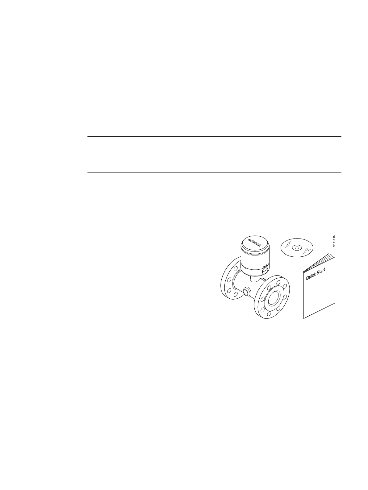
1.1 Items supplied
1
Inspection
● SITRANS F M MAG 8000 Standard, MAG
8000 CT, or MAG 8000 Irrigation
● Calibration certificate
● Operating Instructions
● SITRANS F M documentation disk
1. Check for mechanical damage due to possible improper handling during shipment. All
claims for damage are to be made promptly to the shipper.
2. Make sure the items supplied, and the information on the nameplate corresponds to the
ordering information.
SITRANS MAG 8000
Operating Instructions, 11/2018, A5E03071515-AE 7
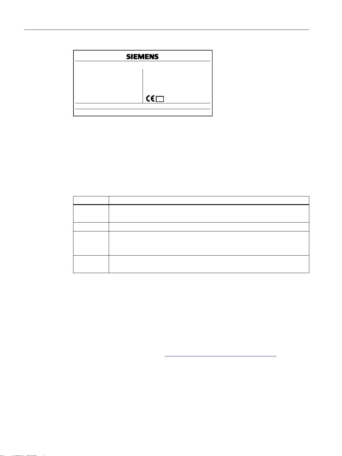
SITRANS F M MAG 8000 CT
0200
M17
Siemens AG, DE-76181 Karlsruhe
Made in France
2UGHU1R
6HULDO1R
6L]H'1LQFK
6HQVRUPDWHULDO
0HWHURULHQWDWLRQ
(QFORVXUH
)OXLG*URXS3('/
&HUWLILFDWLRQ1R
0$:336DWr&r)76
0$:336DWr&r)76
7PHGLDPLQ
7PHGLDPD[
3URFHVVFRQQHFWLRQ
<HDURI0DQXI
6RIWZDUHYHUVLRQ
4PK
0(31&$
+
/LQLQJ(3'0
$670$
+RUL]RQWDO+
(0,31(0$3
&DO)DFWRU
'.0,
EDUSVL
EDUSVL
r&r)
r&r)
$631
44
Introduction
1.3 Further Information
Figure 1-1 MAG 8000 CT nameplate example
1.2 History
The contents of these instructions are regularly reviewed and corrections are included in
subsequent editions. We welcome all suggestions for improvement.
The following table shows the most important changes in the documentation compared to each
previous edition.
Edition Remarks
11/2018
● Update for software version 3.09
● Technical data and Appendix C.2 updated
05/2014
10/2012
● NMI M 10 approval for MAG 8000 Irrigation
● Primary operation software changed from Flow Tool to PDM (Flow Tool moved to
appendix)
● Qualification Certificate functionality added
03/2010
● Integration of MAG 8000 for irrigation applications
● Restructuring of the document
1.3 Further Information
Product information on the Internet
The Operating Instructions are available on the documentation disk shipped with the device,
and on the Internet on the Siemens homepage, where further information on the range of
SITRANS F flowmeters may also be found:
Product information on the internet (
http://www.siemens.com/flowdocumentation)
Worldwide contact person
8 Operating Instructions, 11/2018, A5E03071515-AE
If you need more information or have particular problems not covered sufficiently by these
Operating Instructions, get in touch with your contact person. You can find contact information
for your local contact person on the Internet:
SITRANS MAG 8000

Introduction
1.3 Further Information
Local contact person (http://www.automation.siemens.com/aspa_app/contactmenu.aspx?
ci=yes®id=DEF&lang=en)
SITRANS MAG 8000
Operating Instructions, 11/2018, A5E03071515-AE 9

Introduction
1.3 Further Information
SITRANS MAG 8000
10 Operating Instructions, 11/2018, A5E03071515-AE
Safety notes
2.1 General safety instructions
CAUTION
Correct, reliable operation of the product requires proper transport, storage, positioning and
assembly as well as careful operation and maintenance.
Only qualified personnel should install or operate this instrument.
Note
Alterations to the product, including opening or improper modifications of the product are not
permitted.
If this requirement is not observed, the CE mark and the manufacturer's warranty will expire.
2.2 Laws and directives
2
General requirements
Installation of the equipment must comply with national regulations. For example EN 60079-14
for the European Community.
Instrument safety standards
The device has been tested at the factory, based on the safety requirements. In order to
maintain this condition over the expected life of the device the requirements described in these
Operating Instructions must be observed.
NOTICE
Material compatibility
Siemens Flow Instruments can provide assistance with the selection of wetted sensor parts.
However, the full responsibility for the selection rests with the customer and Siemens Flow
Instruments can take no responsibility for any failure due to material incompatibility.
SITRANS MAG 8000
Operating Instructions, 11/2018, A5E03071515-AE 11

Safety notes
2.5 Installation in hazardous area
2.3 Conformity with European directives
The CE marking on the device symbolizes the conformity with the following European
directives:
Electromagnetic compatibili‐
ty EMC
2014/30/EU
Low voltage directive LVD
2014/35/EU
Atmosphère explosible
ATEX
2014/34/EU
Pressure equipment direc‐
tive PED
2014/68/EU
Measuring instruments direc‐
tive MID
2014/32/EU
The applicable directives can be found in the EU declaration of conformity of the specific device.
2.4 Lithium batteries
Directive of the European Parliament and of the Council on the
harmonisation of the laws of the Member States relating to elec‐
tromagnetic compatibility
Directive of the European Parliament and of the Council on the
harmonisation of the laws of the Member States relating to the
making available on the market of electrical equipment designed
for use within certain voltage limits
Directive of the European Parliament and the Council on the har‐
monisation of the laws of the Member States relating to equip‐
ment and protective systems intended for use in potentially ex‐
plosive atmospheres
Directive of the European Parliament and of the Council on the
harmonisation of the laws of the Member States relating to the
making available on the market of pressure equipment
Directive of the European Parliament and the Council on the har‐
monisation of the laws of the Member States relating to the mak‐
ing available on the market of measuring instruments
Lithium batteries are primary power sources with high energy content designed to provide the
highest possible degree of safety.
WARNING
Potential hazard
Lithium batteries may present a potential hazard if they are abused electrically or
mechanically. Observe the following precautions when handling and using lithium batteries:
● Do not short-circuit, recharge or connect with false polarity.
● Do not expose to temperatures beyond the specified temperature range.
● Do not incinerate.
● Do not crush, puncture or open cells or disassemble.
● Do not weld or solder to the battery’s body.
● Do not expose contents to water.
2.5 Installation in hazardous area
This device is not approved for use in hazardous areas.
SITRANS MAG 8000
12 Operating Instructions, 11/2018, A5E03071515-AE

Description
3.1 System components
A SITRANS F M MAG 8000 water meter system includes:
● A transmitter and a sensor. The transmitter is either compact mounted (integral) or remote
mounted at a distance of maximum 30 m (100 ft).
● An internally or externally mounted battery supply or 115 to 230 V AC or 12/24 V AC/DC
power supply with battery backup.
Communication solutions
The following communication modules are available:
● RS 232
● RS 485 Modbus RTU
● Encoder interface for AMR solutions
● GSM/GPRS module
3
3.2 Operating principle
MAG 8000 is a microprocessor-based water meter with graphical display and key for optimum
customer operation and information on site. The transmitter drives the magnetic field in the
sensor, evaluates the flow signal from the sensor, and calculates the volume passing through.
It delivers the required information via the integrated pulse output or communication interfaces
as part of a system solution. Its intelligent functionality, information and diagnostics ensure
optimum meter performance and information to optimize water supply and billing.
MAG 8000 Standard and MAG 8000 CT can be ordered as a Basic or an Advanced version,
and MAG 8000 Irrigation as Basic version only.
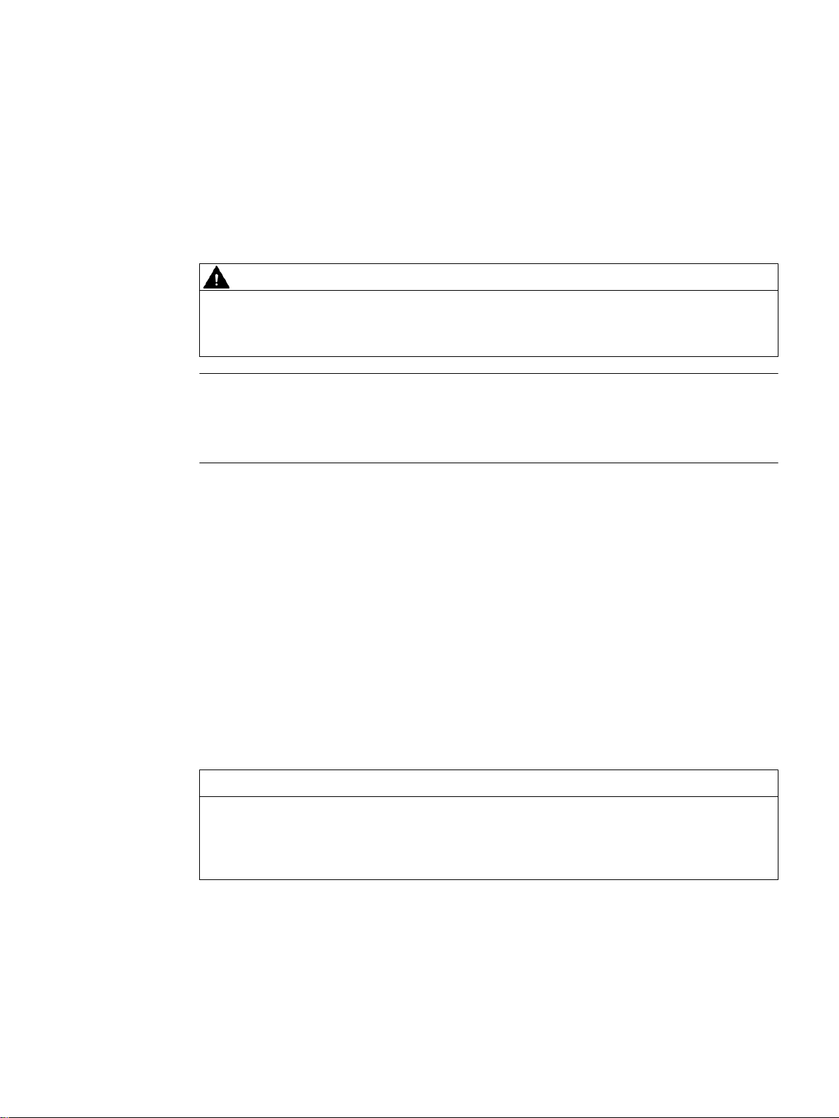
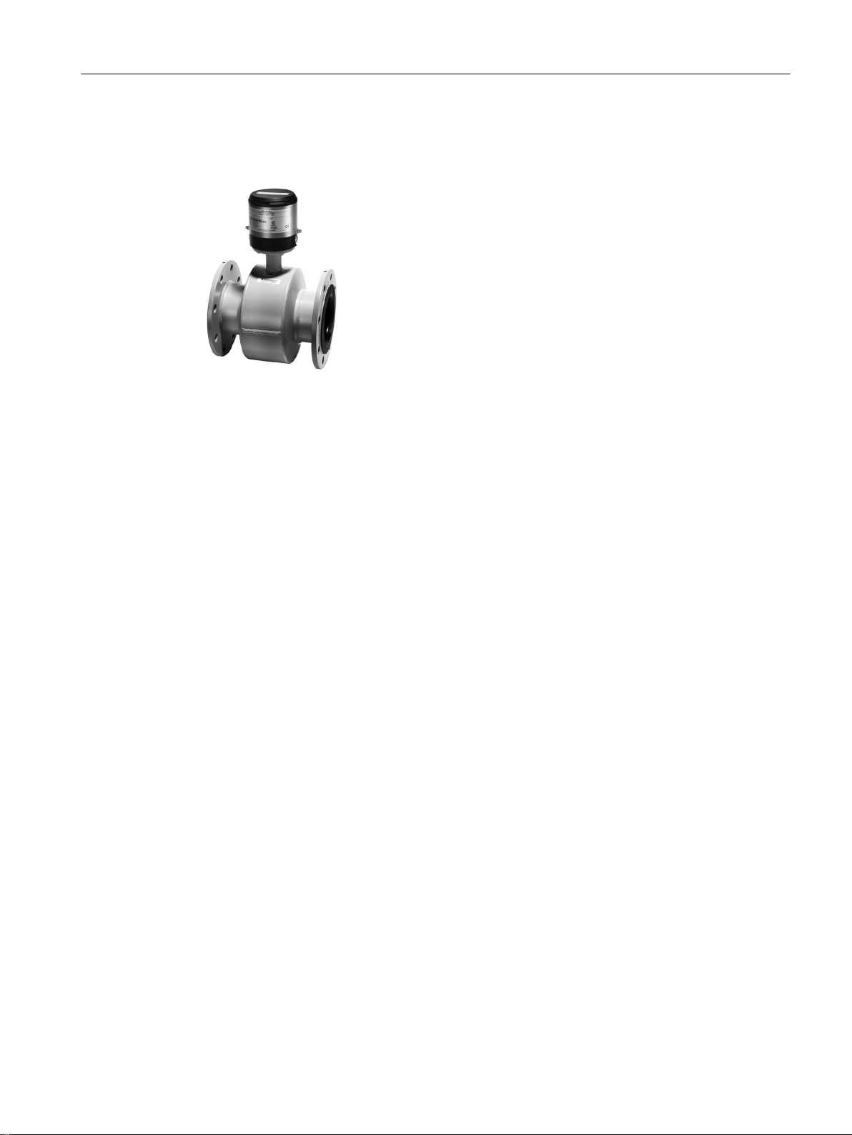
3.3 Design
MAG 8000 is a battery-supplied magnetic inductive water meter for revenue, district and
irrigation metering application.
Figure 3-1 MAG 8000 product program
SITRANS MAG 8000
Operating Instructions, 11/2018, A5E03071515-AE 13
Description
3.3 Design
Compact
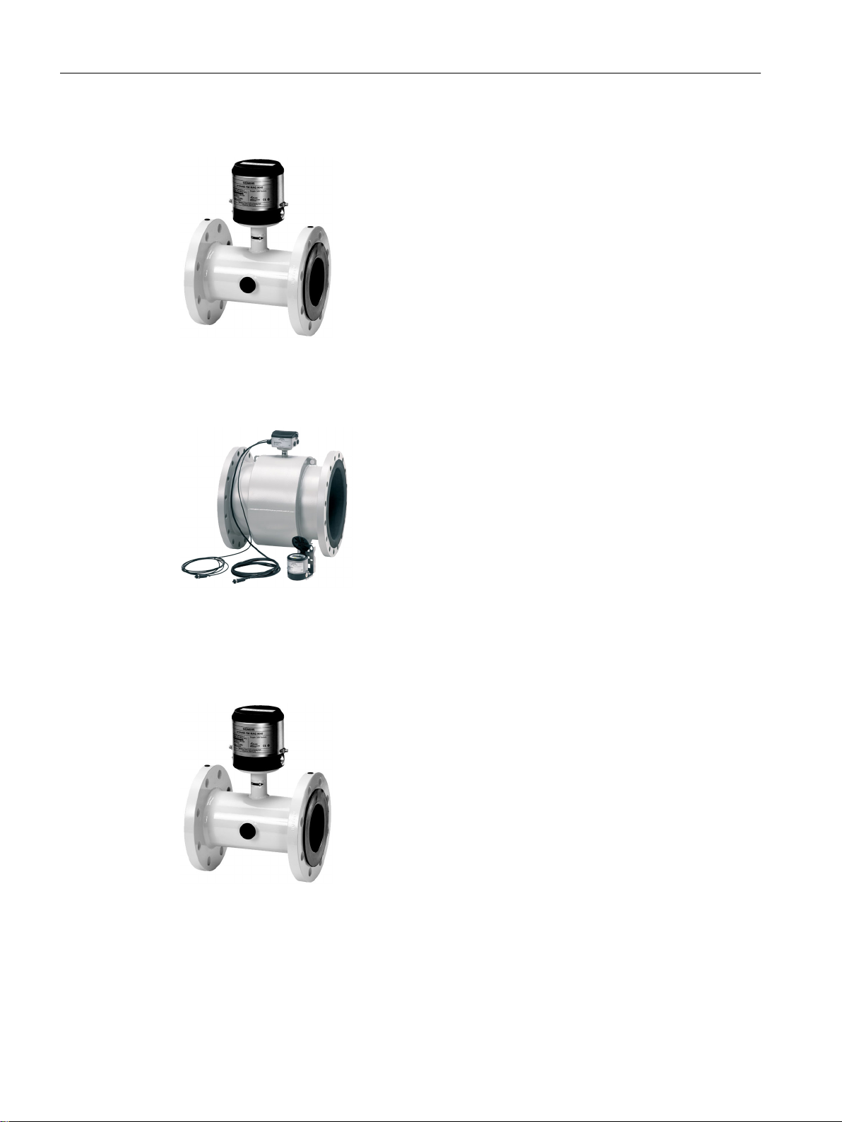
Remote
Figure 3-2 MAG 8000 Standard compact
Custody transfer
Figure 3-3 MAG 8000 Standard remote
Compact and remote versions.
Figure 3-4 MAG 8000 CT (compact version)
SITRANS MAG 8000
14 Operating Instructions, 11/2018, A5E03071515-AE
Irrigation
Compact and remote versions.
Figure 3-5 MAG 8000 Irrigation (compact version)
3.4 Benefits
Description
3.4 Benefits
● Simple placement of the meter - bury the meter underground or in a floating chamber. The
IP 68 (NEMA 6P) design is unaffected by meter position or in-line piping stresses, and there
is no requirement for filters.
● Low pressure loss - an unrestricted flow tube ensures minimal pressure loss, even at the
highest flow rates. Overall network system pressures can be reduced, helping to prevent
leakage from burst pipes and excess stress placed on pumping stations.
● Zero maintenance - designed without moving parts and has a 10-year battery life.
● Measurement in both directions - only one meter required for measuring in both direction.
● Intelligent meter - only one meter for leak detection, data logger function, and self-detection
of errors.
SITRANS MAG 8000
Operating Instructions, 11/2018, A5E03071515-AE 15

Description
3.4 Benefits
SITRANS MAG 8000
16 Operating Instructions, 11/2018, A5E03071515-AE
Installing/Mounting
87L130.10
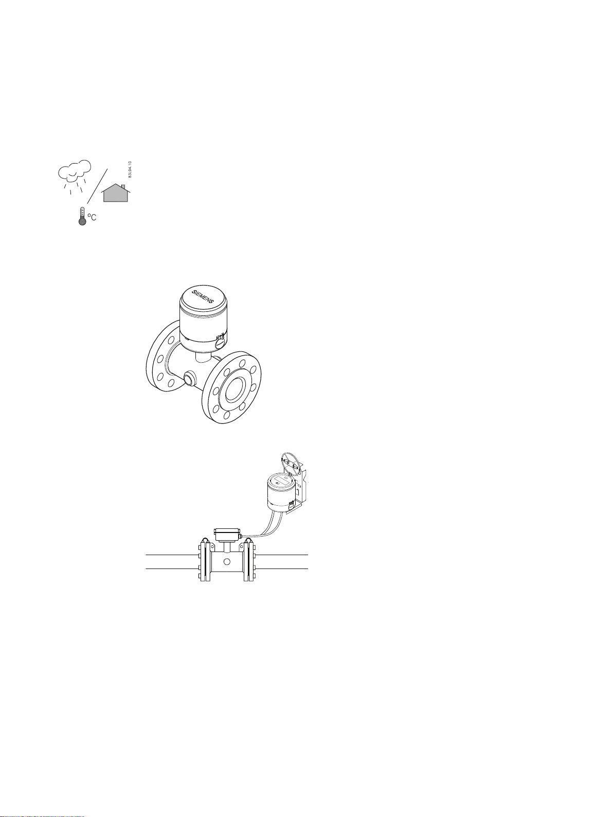
MAG 8000 water meters are suitable for indoor and outdoor installations.
● Make sure that pressure and temperature specifications indicated on the device nameplate /
label are not exceeded.
General information
This chapter describes how to install the water meter in the compact version as well as in the
remote version.
4
Figure 4-1 Compact installation
Figure 4-2 Remote installation
The installation consists of two steps:
1. Sensor installation.
2. Transmitter installation (remote version only).
SITRANS MAG 8000
Operating Instructions, 11/2018, A5E03071515-AE 17
87L166
N
S
)ORZ
GLUHFWLRQ
Installing/Mounting
4.1 Sensor installation
4.1 Sensor installation
The sensor installation consists of three steps:
1. Locating the sensor.
2. Orienting the sensor.
3. Mounting the sensor.
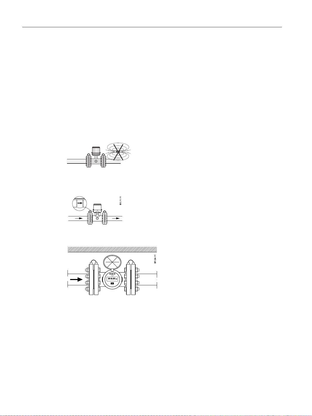
4.1.1 Locating the sensor
Ensure that the sensor is located in the most optimum place and where no magnetic field is
present.
Flow direction
Ensure that sensor is mounted in correct flow direction as indicated on label.
If process flow direction is opposite of flow direction indicated on sensor label, forward flow
rates can be restored via parameter 327, if factor is adjusted to "-1".
MAG 8000 CT is approved for bidirectional measurement.
SITRANS MAG 8000
18 Operating Instructions, 11/2018, A5E03071515-AE
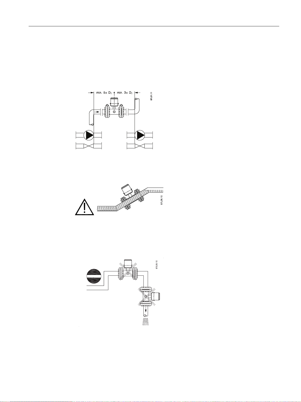
Inlet and outlet condition
To achieve most accurate flow measurement it is essential to have certain straight inlet and
outlet pipe lengths as shown (Di: sensor diameter). MAG 8000 CT is approved for installation
with 0D of straight pipe upstream from the sensor and 0D of straight pipe downstream from
the sensor. It is, however, recommended to follow the installation guidelines for the MAG 8000
Standard water meter for optimal measurement performance.
Installing/Mounting
4.1 Sensor installation
Sensor must be completely full of liquid
Therefore avoid:
● Air in pipe.
● Installation at the highest point in pipe system.
● Installation in vertical pipes with free outlet.
SITRANS MAG 8000
Operating Instructions, 11/2018, A5E03071515-AE 19
Installing/Mounting
4.1 Sensor installation
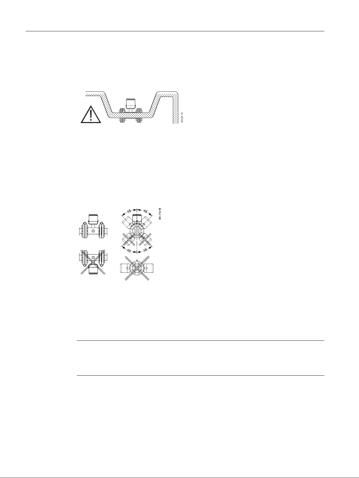
Partially filled pipes
For partially filled pipes or pipes with downwards flow and free outlet, sensor must be mounted
in a U-tube.
4.1.2 Orienting the sensor
MAG 8000 CT DN 50 to DN 150 can be installed in all orentations, while DN 200 to DN 400
can only be installed horizontally.
Horizontal pipes
Sensor must be mounted as shown in upper part of figure. Do not mount sensor as shown in
lower part of figure as electrodes then will be positioned at top where air bubbles may occur
and in bottom, where mud, sludge, sand etc. may deposit and cover the electrode, thus
impacting the measurement.
If "Empty Pipe Detection" is used, sensor should be tilted 45° as shown in upper right figure
to maximize full pipe detection and provide accurate volume calculations.
Note
Physical installation of battery pack may influence battery capacity. Optimal battery capacity
is achieved with battery pack in an upright position. Installation examples marked with dotted
cross will affect battery capacity.
SITRANS MAG 8000
20 Operating Instructions, 11/2018, A5E03071515-AE
Vertical pipes (MAG 8000)
Recommended installation is in a vertical/inclined pipe to minimize wear and deposits in sensor.
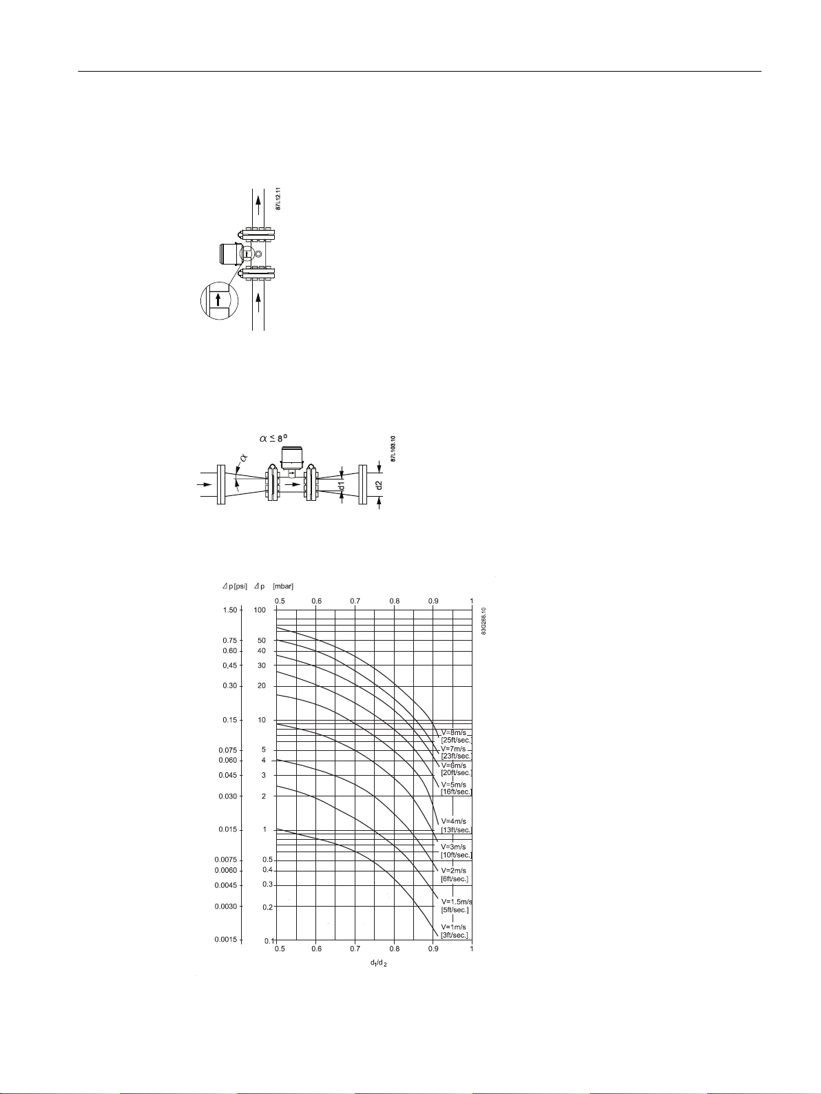
Installation in large pipes (MAG 8000)
The water meter can be installed between two reducers (e.g. DIN 28545).
Installing/Mounting
4.1 Sensor installation
With an 8° reducer, the following pressure drop curve applies. The curves are applicable to
water.
SITRANS MAG 8000
Operating Instructions, 11/2018, A5E03071515-AE 21
Installing/Mounting
4.1 Sensor installation
Example:
A flow velocity of 3 m/s (10 ft./sec.) (V) in a sensor with a diameter reduction from DN 100 to
DN 80 (4" to 3") (d1/d2 = 0.8) gives a pressure drop of 2.9 mbar (0.04 psi).
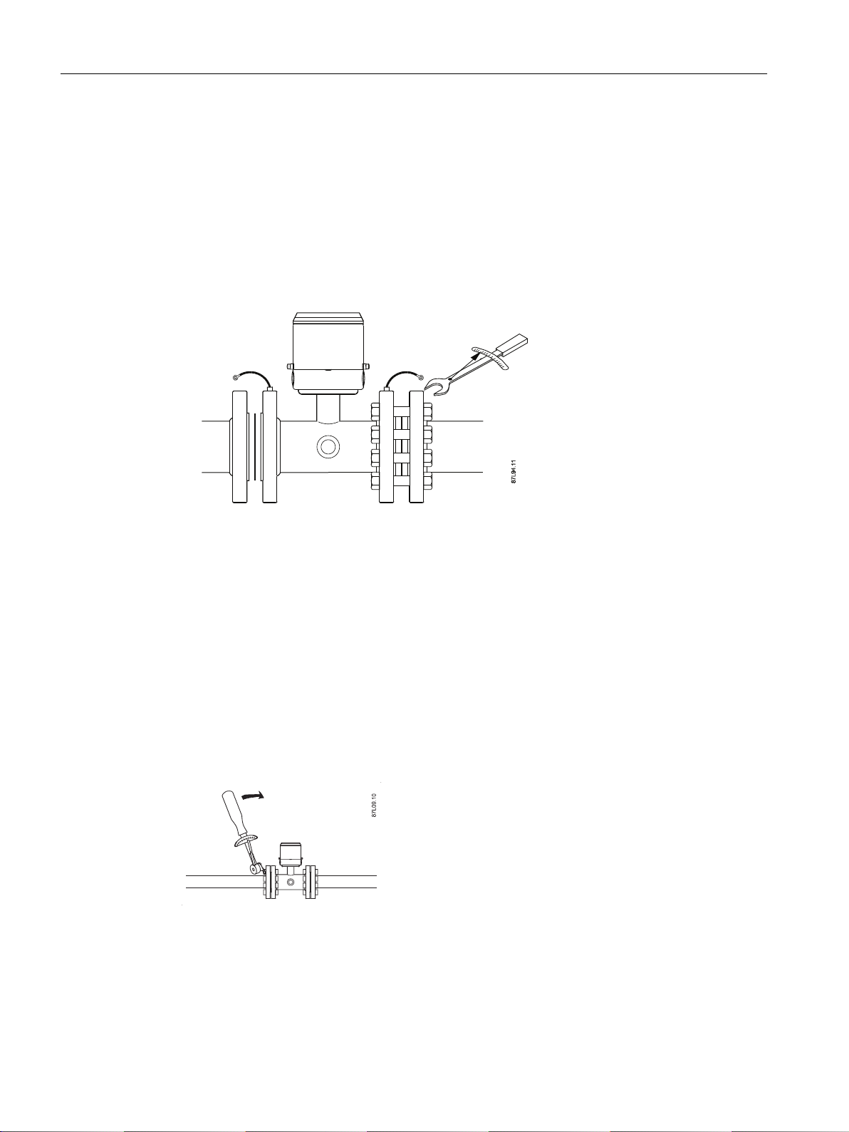
4.1.3 Mounting the sensor
1. Install gaskets.
2. Ensure connection flange has a smooth surface and is in line with sensor.
Gaskets are recommended but not included in water meter delivery.
Advice for gasket selection:
● Only use flat rubber gaskets.
● Thickness 1 to 6 mm (0.0 to 0.02 ft) dependent on gap/tolerance.
● Inner diameter must be larger than bore of water meter.
● Material should be compatible with process fluid.
● Hardness should be maximum 75 Shore A.
Maximum allowable torques
Standard bolts must be well lubricated and tightened evenly around gasket.
Leakage/damage to water meter or piping may arise if bolts are overtightened.
Torque calculations
SITRANS MAG 8000
22 Operating Instructions, 11/2018, A5E03071515-AE

Installing/Mounting
4.1 Sensor installation
All values are theoretical and are calculated on the assumption that:
● All bolts are new and material selection is according to EN 1515-1 table 2.
● Gasket material not exceeding 75 shore A is used between the water meter and mating
flanges.
● All bolts are galvanized and adequately lubricated.
● Flanges are made of carbon steel.
● Water meter and mating flanges are correctly aligned.
Torques for 7ME6810 and 7ME6820
Nominal size PN 10 PN 16 PN 40 Class 150 AWWA
Mm inch Nm f/lbs Nm f/lbs Nm f/lbs Nm f/lbs Nm f/lbs
25 1" N/A N/A N/A N/A 10 7 7 5 N/A N/A
40 1½" N/A N/A N/A N/A 16 12 9 7 N/A N/A
50 2" N/A N/A 25 18 N/A N/A 25 18 N/A N/A
65 2½" N/A N/A 25 18 N/A N/A 25 18 N/A N/A
80 3" N/A N/A 25 18 N/A N/A 34 25 N/A N/A
100 4" N/A N/A 25 18 N/A N/A 26 19 N/A N/A
125 5" N/A N/A 29 21 N/A N/A 42 31 N/A N/A
150 6" N/A N/A 50 37 N/A N/A 57 42 N/A N/A
200 8" 50 37 50 37 N/A N/A 88 65 N/A N/A
250 10" 50 37 82 61 N/A N/A 99 73 N/A N/A
300 12" 57 42 111 82 N/A N/A 132 97 N/A N/A
350 14" 60 44 120 89 N/A N/A 225 166 N/A N/A
400 16" 88 65 170 125 N/A N/A 210 155 N/A N/A
450 18" 92 68 170 125 N/A N/A 220 162 N/A N/A
500 20" 103 76 230 170 N/A N/A 200 148 N/A N/A
600 24" 161 119 350 258 N/A N/A 280 207 N/A N/A
700 28" 200 148 304 224 N/A N/A N/A N/A 200 148
750 30" N/A N/A N/A N/A N/A N/A N/A N/A 240 177
800 32" 274 202 386 285 N/A N/A N/A N/A 260 192
900 36" 288 213 408 301 N/A N/A N/A N/A 240 177
1000 40" 382 282 546 403 N/A N/A N/A N/A 280 207
1050 42" N/A N/A N/A N/A N/A N/A N/A N/A 280 207
1100 44" N/A N/A N/A N/A N/A N/A N/A N/A 290 214
1200 48" 395 292 731 539 N/A N/A N/A N/A 310 229
Torques for 7ME6880
Nominal
size
Mm inch Nm f/lbs Nm f/lbs Nm f/lbs Nm f/lbs Nm f/lbs
25 1" N/A N/A N/A N/A N/A N/A N/A N/A 6 4
SITRANS MAG 8000
Operating Instructions, 11/2018, A5E03071515-AE 23
EN drilled
pattern
PN 7
ANSI dril‐
led pattern
Class150
AS2091
drilled pat‐
tern
PN 7
AS4087
PN 16
AS2129 Tabel E
PN 14

Installing/Mounting
4.1 Sensor installation
Nominal
size
40 1,5" N/A N/A N/A N/A N/A N/A N/A N/A 9 7
50 2" 5 4 5 4 5 4 21 15 N/A N/A
65 2½" 5 4 7 5 7 6 22 16 N/A N/A
80 3" 5 4 9 7 9 7 32 24 N/A N/A
100 4" 7 6 7 6 14 11 50 37 N/A N/A
125 5" 11 9 12 9 11 9 N/A N/A 33 24
150 6" 16 12 15 11 12 9 60 44 N/A N/A
200 8" 24 18 23 17 20 15 55 41 N/A N/A
250 10" 24 18 26 20 36 27 94 70 N/A N/A
300 12" 31 23 35 26 31 23 72 53 N/A N/A
350 14" 32 24 40 30 51 38 153 113 N/A N/A
400 16" 46 34 50 37 62 46 172 127 N/A N/A
450 18" 47 35 56 42 79 59 224 165 N/A N/A
500 20" 57 43 67 50 72 54 198 146 N/A N/A
600 24" 89 66 104 77 111 82 287 211 N/A N/A
700 N/A N/A N/A N/A N/A N/A N/A 228 168 N/A N/A
750 N/A N/A N/A N/A N/A N/A N/A N/A N/A N/A N/A
800 N/A N/A N/A N/A N/A N/A N/A 426 314 N/A N/A
900 N/A N/A N/A N/A N/A N/A N/A 416 307 N/A N/A
1000 N/A N/A N/A N/A N/A N/A N/A 386 284 N/A N/A
1050 N/A N/A N/A N/A N/A N/A N/A N/A N/A N/A N/A
1100 N/A N/A N/A N/A N/A N/A N/A N/A N/A N/A N/A
1200 N/A N/A N/A N/A N/A N/A N/A 443 327 N/A N/A
EN drilled
pattern
PN 7
ANSI dril‐
led pattern
Class150
AS2091
drilled pat‐
tern
PN 7
AS4087
PN 16
AS2129 Tabel E
PN 14
SITRANS MAG 8000
24 Operating Instructions, 11/2018, A5E03071515-AE
4.2 Potential equalization
87L150
/
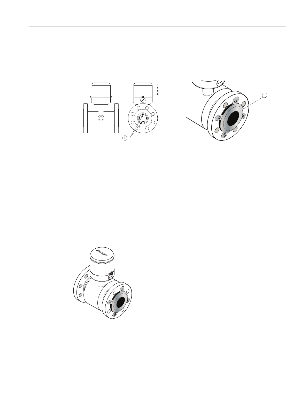
Liquid potential equalization or grounding is accomplished with built-in grounding electrodes
and/or grounding rings. The electrodes ensure electrical connection between liquid and meter
providing a stable and accurate measurement.
Installing/Mounting
4.3 Grounding
① Built-in grounding electrode
(7ME6810 and 7ME6820)
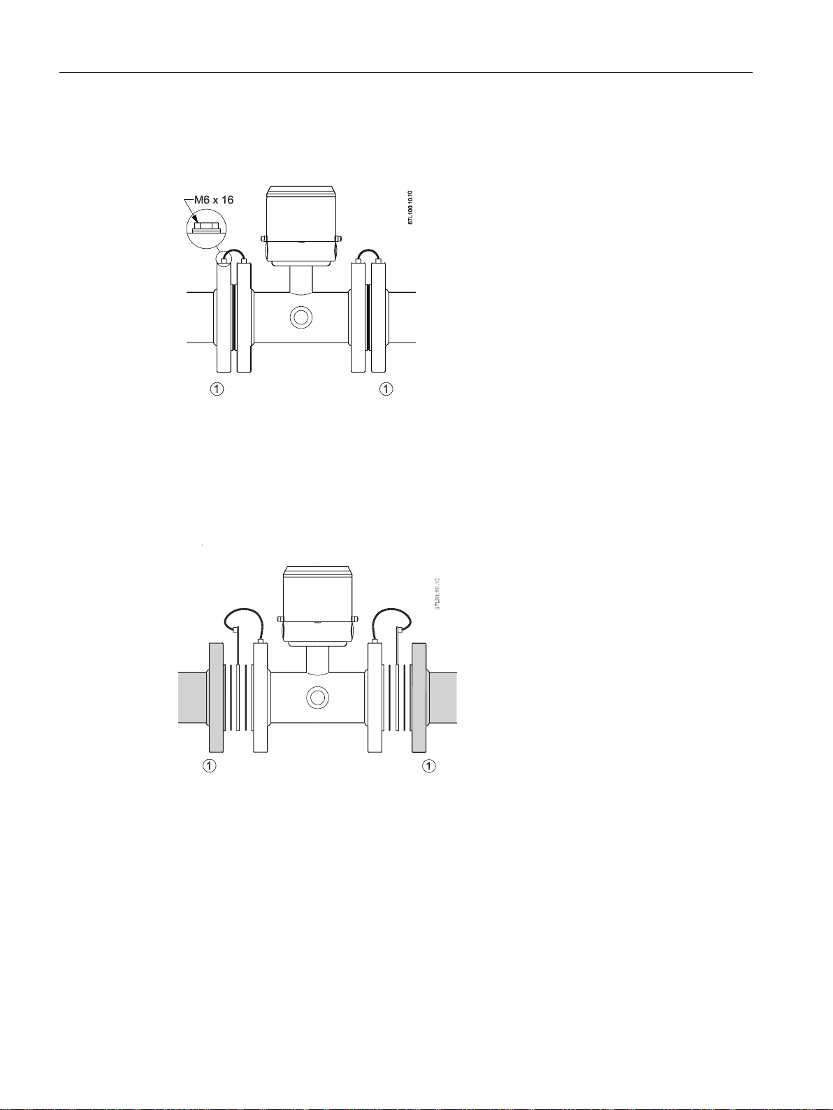
4.3 Grounding
The sensor body must be grounded using grounding/bonding straps and/or grounding rings
to protect flow signal against stray electrical noise and/or lightning. This ensures that noise is
carried through sensor body and that the measuring area within sensor body is noise-free.
Irrigation applications
MAG 8000 Irrigation device is always delivered with pre-mounted grounding rings. Grounding
rings are mandatory for MAG 8000 Irrigation.
② Grounding rings pre-mounted on
MAG 8000 Irrigation (7ME6880)
SITRANS MAG 8000
Operating Instructions, 11/2018, A5E03071515-AE 25
Installing/Mounting
4.3 Grounding
Metal pipes
Connect straps to both flanges with 6 mm (1/4") screws.
① Metal pipes
Bonding/grounding straps are part of delivery and pre-mounted on water meter.
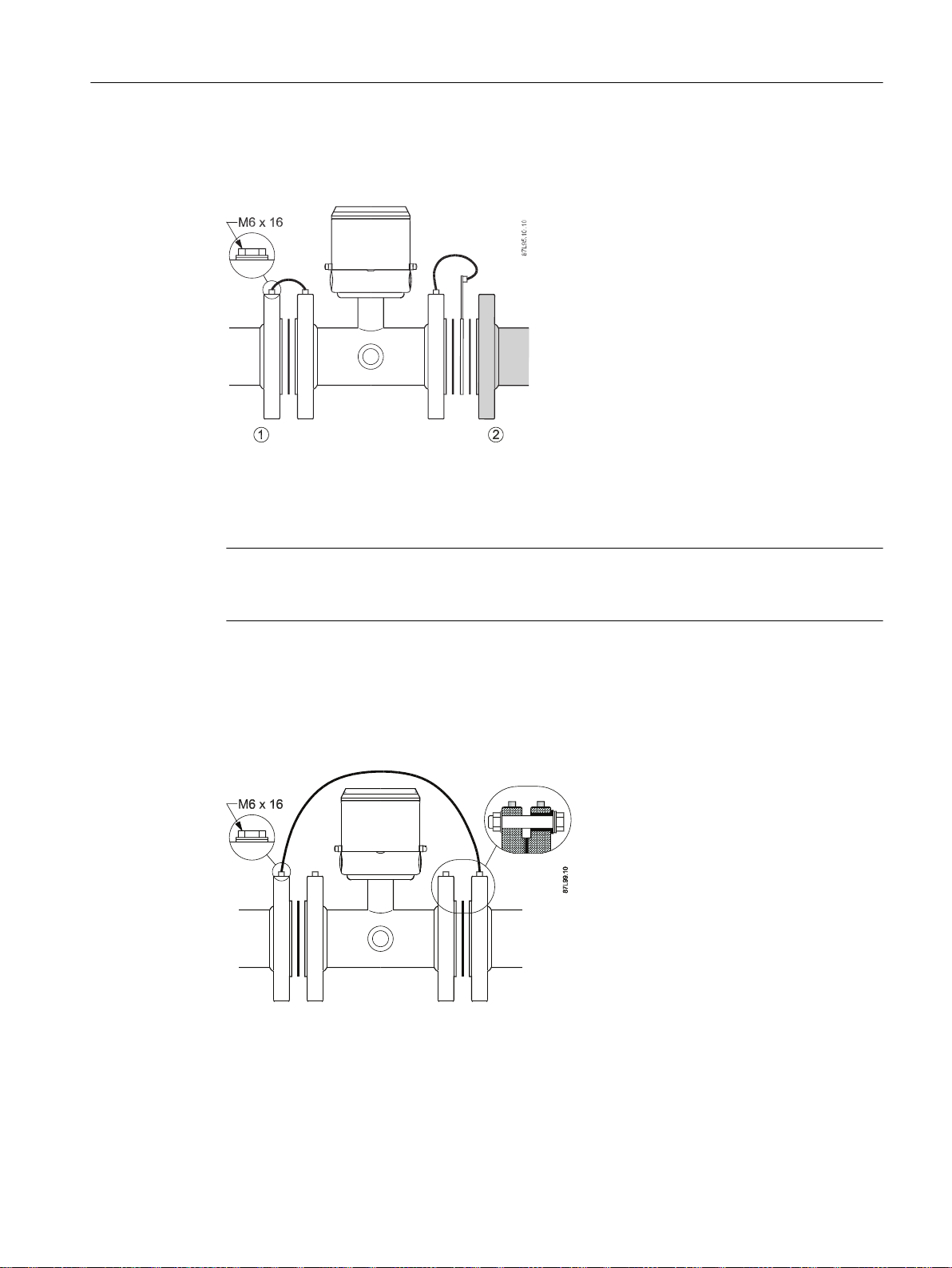
Plastic pipes and lined metal pipes
Use optional grounding rings at both ends.
① Plastic pipes or lined metal pipes
Grounding rings are not included in delivery.
SITRANS MAG 8000
26 Operating Instructions, 11/2018, A5E03071515-AE
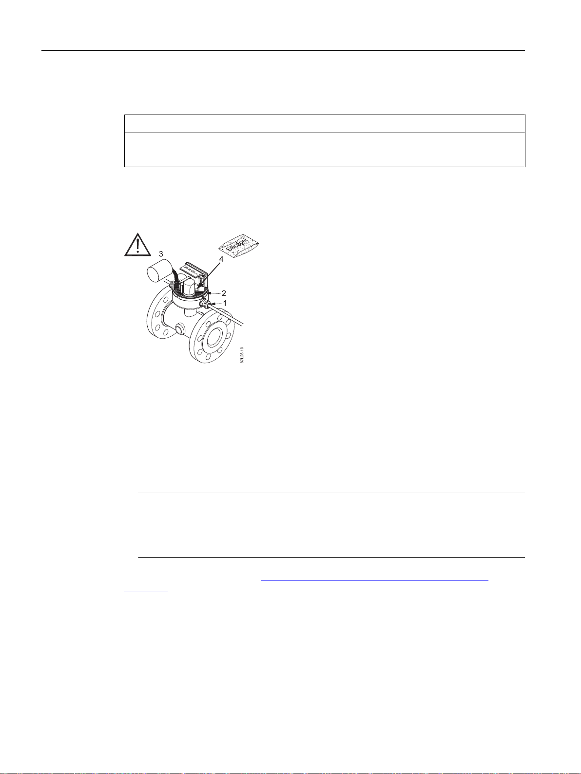
Combination of metal and plastic pipes
Use straps for metal pipe and grounding rings for plastic pipe.
① Metal pipe
② Plastic pipe
Bonding/grounding straps, grounding rings and straps are not included in delivery.
Installing/Mounting
4.4 Cathodic-protected pipes
Note
All straps or grounding wires must be 12 AWG (or heavier) copper wire and connected with 6
mm screws.
4.4 Cathodic-protected pipes
Pay special attention to meter installation in cathodic-protected pipe.
Isolate meter from pipeline by mounting isolation sleeves and washers on flange bolts and
connect a wire dimensioned to manage the cathodic current and environmental influence,
between pipelines.
SITRANS MAG 8000
Operating Instructions, 11/2018, A5E03071515-AE 27
Installing/Mounting
4.5 Potting and direct burial
4.5 Potting and direct burial
NOTICE
Electrical connections
Do not pot meter before electrical connections have been made.
Meter is rated IP68/NEMA 6P from the factory as standard. If cable glands are used, IP68/
NEMA 6P enclosure rating is obtained by potting transmitter bottom with Sylgard potting kit.
Otherwise only an IP67/NEMA 4 rating is obtained.
Sealing of transmitter
1. Select the proper gland size to fit installed cable size.
2. Mount O-ring properly and correctly and grease with gel.
3. Fill Sylgard potting kit in bottom part of casing.
4. Renew Silicagel bag (placed behind battery cup) to prevent condensation within meter, if
necessary.
5. Mount the enclosure carefully and make sure not to damage the O-ring.
Note
Potting
Ensure not to fill Sylgard potting kit in the space for the battery pack.
Ensure Silicagel bag is not in contact with Sylgard potting.
See also Potting kit instruction (http://support.automation.siemens.com/WW/view/en/
43208835).
SITRANS MAG 8000
28 Operating Instructions, 11/2018, A5E03071515-AE
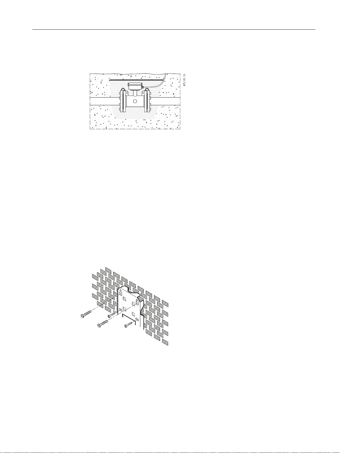
Direct burial of remote sensor
*
Remote sensor is protected to IP68/NEMA 6P and can be buried.
The use of pea gravel, at least 300 mm (12 inches) all around sensor, is mandatory to provide
some drainage and to prevent dirt from solidifying on sensor.
It also helps to locate the sensor should excavation be necessary. Before covering pea gravel
with earth, use electrical cable identification tape above gravel.
Run remote sensor cable through a plastic conduit of minimum 50 mm (2 inches).
Installing/Mounting
4.6 Transmitter installation
4.6 Transmitter installation
Mount bracket on a wall as shown below or on a horizontal or a vertical pipe using ordinary
hose clips or duct straps.
Wall mounting
Figure 4-3 Wall mounting
SITRANS MAG 8000
Operating Instructions, 11/2018, A5E03071515-AE 29
*
*
Installing/Mounting
4.6 Transmitter installation
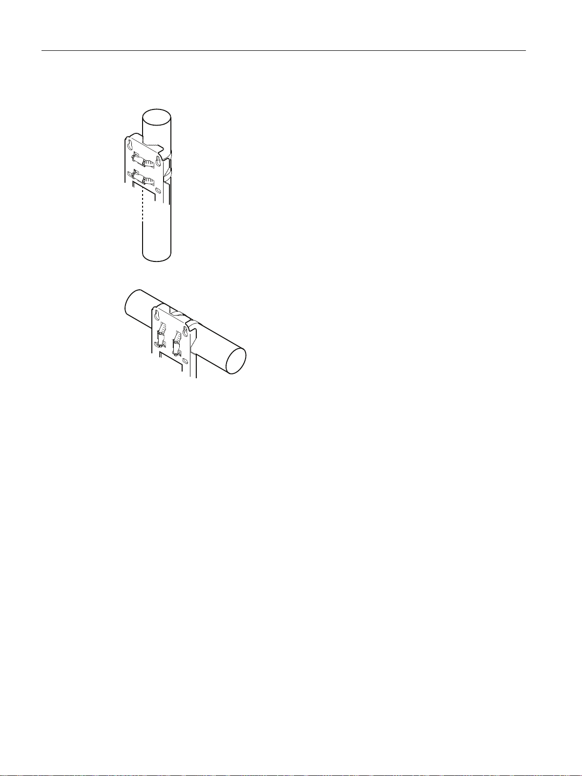
Pipe mounting
Figure 4-4 Pipe mounting - vertical
Figure 4-5 Pipe mounting - horizontal
SITRANS MAG 8000
30 Operating Instructions, 11/2018, A5E03071515-AE
Loading...