

Siemens SITRANS F MAG 6000 I, SITRANS F MAG 6000 EX DE Operating Instructions Manual

SITRANS F
Electromagnetic Flowmeters
MAG 6000 I / MAG 6000 I Ex de transmitter
Operating Instructions
04/2016Edition
Answers for industry.


SITRANS F
Electromagnetic Flowmeters
MAG 6000 I / MAG 6000 I Ex de
transmitter
Operating Instructions
Electromagnetic flow transmitter designed for use with
flow sensor types
MAG 1100/1100 HT/1100 F/5100 W/
3100 P/3100/3100 HT
Compact and remote installation
04/2016
A5E02083319
Introduction
1
Safety notes
2
Description
3
Installing/Mounting
4
Connecting
5
Commissioning
6
Functions
7
Alarm, error, and system
messages
8
Service and maintenance
9
Troubleshooting/FAQs
10
Technical data
11
Spare parts/Accessories
12
Menu diagrams
A
Factory settings
B
Control drawing
C
-AG

Siemens AG
Division Process Industries and Drives
Postfach 48 48
90026 NÜRNBERG
GERMANY
Document order number: A5E02083319
Ⓟ
Copyright © Siemens AG 2012 - 2016.
All rights reserved
Legal information
Warning notice system
DANGER
indicates that death or severe personal injury will result if proper precautions are not taken.
WARNING
may
CAUTION
indicates that minor personal injury can result if proper precautions are not taken.
NOTICE
indicates that property damage can result if proper precautions are not taken.
Qualified Personnel
personnel qualified
Proper use of Siemens products
WARNING
Siemens products may only be used for the applications described in the catalog and in the relevant technical
maintenance are required to ensure that the products operate safely and without any problems. The permissible
ambient conditions must be complied with. The information in the relevant documentation must be observed.
Trademarks
Disclaimer of Liability
This manual contains notices you have to observe in order to ensure your personal safety, as well as to prevent
damage to property. The notices referring to your personal safety are highlighted in the manual by a safety alert
symbol, notices referring only to property damage have no safety alert symbol. These notices shown below are
graded according to the degree of danger.
indicates that death or severe personal injury
If more than one degree of danger is present, the warning notice representing the highest degree of danger will
be used. A notice warning of injury to persons with a safety alert symbol may also include a warning relating to
property damage.
result if proper precautions are not taken.
The product/system described in this documentation may be operated only by
task in accordance with the relevant documentation, in particular its warning notices and safety instructions.
Qualified personnel are those who, based on their training and experience, are capable of identifying risks and
avoiding potential hazards when working with these products/systems.
Note the following:
documentation. If products and components from other manufacturers are used, these must be recommended
or approved by Siemens. Proper transport, storage, installation, assembly, commissioning, operation and
All names identified by ® are registered trademarks of Siemens AG. The remaining trademarks in this publication
may be trademarks whose use by third parties for their own purposes could violate the rights of the owner.
We have reviewed the contents of this publication to ensure consistency with the hardware and software
described. Since variance cannot be precluded entirely, we cannot guarantee full consistency. However, the
information in this publication is reviewed regularly and any necessary corrections are included in subsequent
editions.
for the specific
04/2016 Subject to change

Table of contents
1 Introduction ............................................................................................................................................. 7
2 Safety notes .......................................................................................................................................... 11
3 Description ............................................................................................................................................ 19
4 Installing/Mounting ................................................................................................................................ 23
5 Connecting ........................................................................................................................................... 29
1.1 Preface ...................................................................................................................................... 7
1.2 Items supplied ........................................................................................................................... 7
1.3 History ....................................................................................................................................... 7
1.4 Device identification .................................................................................................................. 8
1.5 Further Information ................................................................................................................... 9
2.1 General safety instructions ..................................................................................................... 11
2.2 Laws and directives ................................................................................................................ 11
2.3 Installation in hazardous area ................................................................................................. 12
2.3.1 ATEX 2 GD approval .............................................................................................................. 13
2.3.2 FM/CSA Class I, Zone 1 approval .......................................................................................... 17
2.3.3 FM Class I, II, III, Div 1 approval ............................................................................................. 18
2.4 Certificates .............................................................................................................................. 18
3.1 Applications ............................................................................................................................. 19
3.2 System components ............................................................................................................... 19
3.3 Design ..................................................................................................................................... 20
3.4 Features .................................................................................................................................. 21
3.5 Theory of operation ................................................................................................................. 22
4.1 Installation safety precautions ................................................................................................ 23
4.2 Installation conditions.............................................................................................................. 23
4.3 Compact installation ................................................................................................................ 24
4.4 Remote installation ................................................................................................................. 25
4.4.1 Wall mounting using standard mounting plate ........................................................................ 27
4.4.2 Pipe or wall mounting with assembly bracket ......................................................................... 27
5.1 Safety precautions .................................................................................................................. 30
5.2 Electrical connection ............................................................................................................... 31
5.3 Connection of sensor and transmitter in remote version ........................................................ 33
5.4 Wiring in hazardous area ........................................................................................................ 36
5.5 Connection of bus communication add-on modules ............................................................... 37
MAG 6000 I / MAG 6000 I Ex de transmitter
Operating Instructions, 04/2016, A5E02083319-AG
3

Table of contents
6 Commissioning ..................................................................................................................................... 39
7 Functions .............................................................................................................................................. 47
8 Alarm, error, and system messages ...................................................................................................... 51
9 Service and maintenance ...................................................................................................................... 55
10 Troubleshooting/FAQs .......................................................................................................................... 59
11 Technical data ...................................................................................................................................... 61
12 Spare parts/Accessories ....................................................................................................................... 71
5.6 Reassembling the device ....................................................................................................... 37
6.1 Local user interface ................................................................................................................ 39
6.2 Menu structure ....................................................................................................................... 41
6.3 Changing password ............................................................................................................... 42
6.4 Changing basic settings ......................................................................................................... 42
6.5 Changing operator menu setup ............................................................................................. 45
6.6 Changing language ................................................................................................................ 46
7.1 Introduction ............................................................................................................................ 47
7.2 Output settings ....................................................................................................................... 47
7.3 External input ......................................................................................................................... 48
7.4 Sensor characteristics ............................................................................................................ 49
7.5 Reset mode ............................................................................................................................ 49
7.6 Service mode ......................................................................................................................... 49
8.1 Diagnostics ............................................................................................................................. 51
8.2 List of error numbers .............................................................................................................. 53
9.1 Maintenance ........................................................................................................................... 55
9.2 Unit repair ............................................................................................................................... 55
9.3 Technical support ................................................................................................................... 55
9.4 Return procedures ................................................................................................................. 56
10.1 Troubleshooting guide ........................................................................................................... 59
10.2 Transmitter check list ............................................................................................................. 60
11.1 Technical specifications ......................................................................................................... 61
11.2 Dimensions and weight .......................................................................................................... 63
11.3 Accuracy ................................................................................................................................ 64
11.4 Output characteristics ............................................................................................................ 65
11.5 Cable data .............................................................................................................................. 67
11.6 Cable requirements ................................................................................................................ 68
12.1 Ordering ................................................................................................................................. 71
MAG 6000 I / MAG 6000 I Ex de transmitter
4 Operating Instructions, 04/2016, A5E02083319-AG

Table of contents
A Menu diagrams ..................................................................................................................................... 73
B Factory settings .................................................................................................................................... 89
C Control drawing ..................................................................................................................................... 99
Index................................................................................................................................................... 103
12.2 Accessories ............................................................................................................................. 71
12.3 Spare parts ............................................................................................................................. 72
A.1 Transmitter menu overview .................................................................................................... 73
A.2 Basic settings .......................................................................................................................... 75
A.3 Current output ......................................................................................................................... 76
A.4 Digital output - pulse ............................................................................................................... 77
A.5 Digital output - frequency ........................................................................................................ 77
A.6 Error level ................................................................................................................................ 77
A.7 Error number ........................................................................................................................... 78
A.8 Direction/limit .......................................................................................................................... 78
A.9 Batch ....................................................................................................................................... 79
A.10 External input .......................................................................................................................... 80
A.11 Sensor characteristics............................................................................................................. 81
A.12 Reset mode ............................................................................................................................. 82
A.13 Service mode .......................................................................................................................... 83
A.14 Operator menu setup .............................................................................................................. 84
A.15 Product identity ....................................................................................................................... 86
A.16 Add-on communication module .............................................................................................. 87
B.1 Transmitter factory settings .................................................................................................... 89
B.2 50 Hz Dimension dependent Qmax ........................................................................................ 91
B.3 60 Hz Dimension dependent .................................................................................................. 92
B.4 50 Hz Dimension dependent batch and pulse output settings ............................................... 94
B.5 60 Hz Dimension dependent batch and pulse output settings ............................................... 96
C.1 Control drawing ....................................................................................................................... 99
MAG 6000 I / MAG 6000 I Ex de transmitter
Operating Instructions, 04/2016, A5E02083319-AG
5

Table of contents
MAG 6000 I / MAG 6000 I Ex de transmitter
6 Operating Instructions, 04/2016, A5E02083319-AG

1
1.1
Preface
Note
It is the responsibility of the
operating instructions are read, understood, and followed by the relevant personnel before
installing the device.
1.2
Items supplied
•
•
•
•
1.3
History
These instructions contain all the information you need for using the device.
The instructions are aimed at persons mechanically installing the device, connecting it
electrically, configuring the parameters and commissioning it, as well as service and
maintenance engineers.
customer that the instructions and directions provided in the
SITRANS F M MAG 6000 I or MAG 6000 I
Ex de transmitter
Wall mounting bracket (remote version)
SITRANS F M literature CD containing
software, certificates and device manuals
Quick start guide
The contents of these instructions are reviewed regularly and any corrections included in
subsequent editions. We welcome all suggestions for improvement.
MAG 6000 I / MAG 6000 I Ex de transmitter
Operating Instructions, 04/2016, A5E02083319-AG
7

Introduction
Edition
Remarks
HW version
SW version
1.4
Device identification
Inspection
1.4 Device identification
The following table lists the most important changes made to the documentation in the
current and previous editions.
03/2011
12/2011
09/2012
01/2015
04/2016
• First edition
• Transmitter upgrade information included
• Updated ATEX approval
• General update
• Enhanced current output function
• Updated menu functions; possibility of showing user
defined units in display
• Updated ATEX approval
• General update
• Graphics, technical data and factory settings
changed to comprise:
– "BBL42" is displayed as the default setting in
customer unit instead of "?". The unit can still be
changed.
– Improved minimum supply voltage for current
output to 12 V.
• Document revision identification changed according
to new SIEMENS standard
• Various technical specifications updated
• Control drawing updated
3.04
4.04
4.06 X06 4.08 X06
4.06 X06 4.06 X06
08
09
4.06 X06
4.07 X06
4.04
1. Check for mechanical damage due to possible improper handling during shipment. All
claims for damage are to be made promptly to the carrier.
2. Make sure the scope of delivery, and the information on the namelate corresponds to the
ordering information
MAG 6000 I / MAG 6000 I Ex de transmitter
8 Operating Instructions, 04/2016, A5E02083319-AG
Introduction
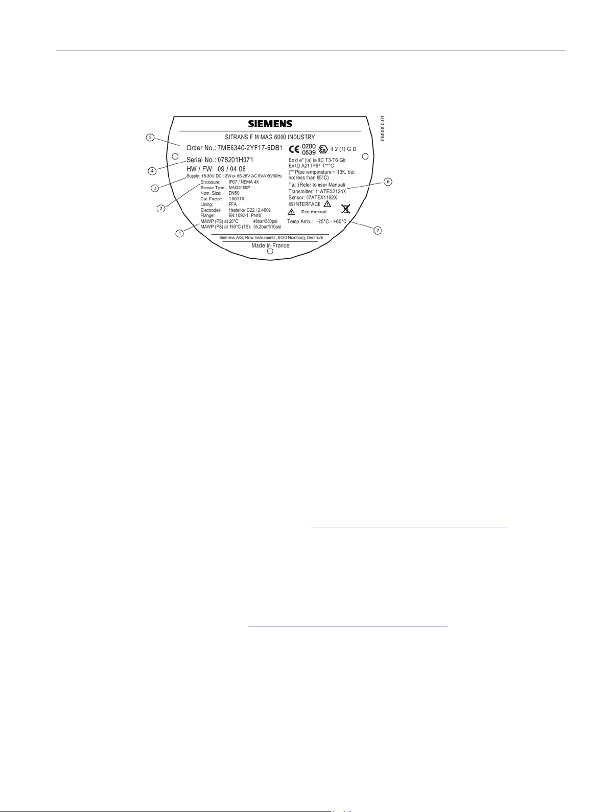
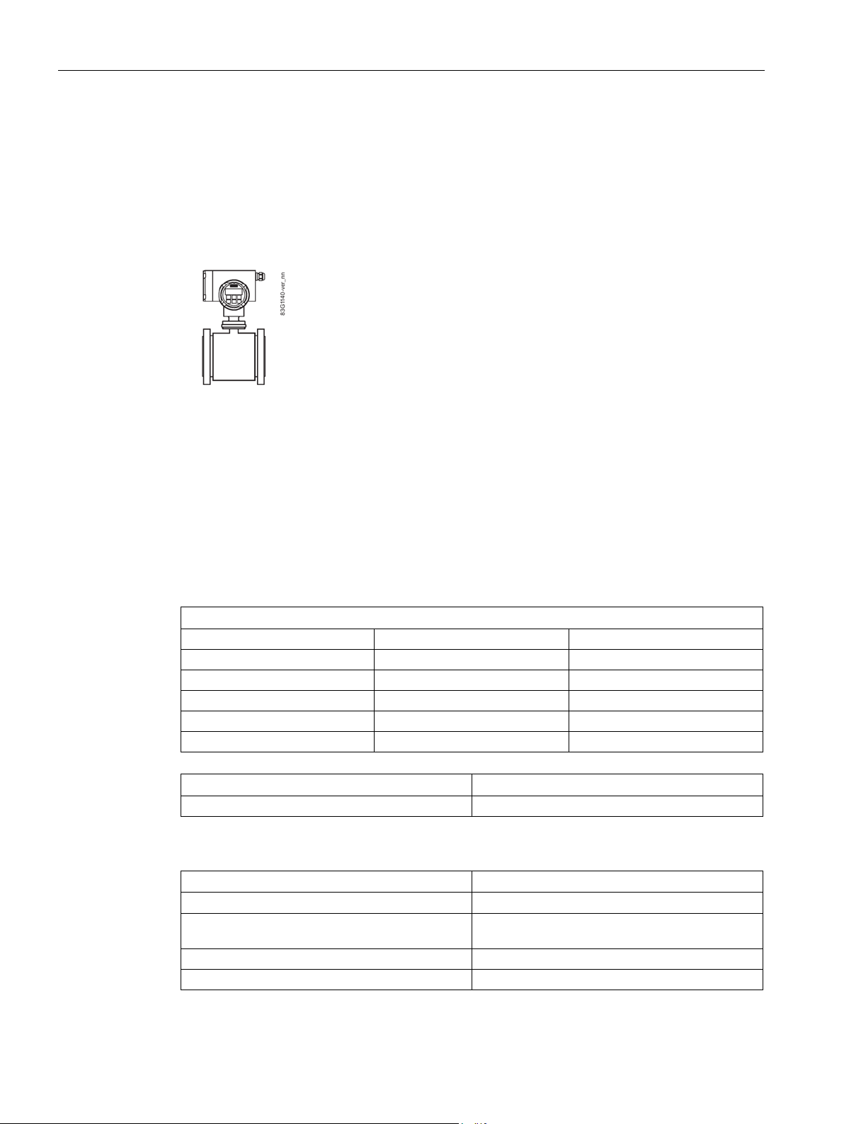
Identification
①
MAWP (Maximum Allowable Working Pressure) at defined temperature, e.g. 20°C
②
Enclosure rating
③
Power supply
④
Serial number
⑤
Code number
⑥
Approvals
⑦
Ambient temperature
1.5
Further Information
Product information on the Internet
Worldwide contact person
1.5 Further Information
Image 1-1 Example of MAG 6000 I Ex nameplate
The Operating Instructions are available on the CD-ROM shipped with the device, and
on the Internet on the Siemens homepage, where further information on the range of
SITRANS F flowmeters may also be found:
Product information on the internet (http://www.siemens.com/flowdocumentation
If you need more information or have particular problems not covered sufficiently by these
Operating Instructions, get in touch with your contact person. You can find contact
information for your local contact person on the Internet:
Local contact person (http://www.automation.siemens.com/partner
)
)
MAG 6000 I / MAG 6000 I Ex de transmitter
Operating Instructions, 04/2016, A5E02083319-AG
9

Introduction
1.5 Further Information
MAG 6000 I / MAG 6000 I Ex de transmitter
10 Operating Instructions, 04/2016, A5E02083319-AG
2
2.1
General safety instructions
CAUTION
Note
Alterations to the product, including opening or improper modifications of the product, are not
permitted.
If this requirement is not observed, the CE mark and the manufacturer's warranty will expire.
2.2
Laws and directives
General requirements
Instrument safety standards
Correct, reliable operation of the product requires proper transport, storage, positioning and
assembly as well as careful operation and maintenance. Only qualified personnel should
install or operate this instrument.
Installation of the equipment must comply with national regulations. For example EN 6007914 for the European Community.
The device has been tested at the factory, based on the safety requirements. In order to
maintain this condition over the expected life of the device, the requirements described in
these Operating Instructions must be observed.
Environmental conditions according to IEC61010-1:
● Indoor/Outdoor use
● Altitude up to 2000 m
● Maximum relative humidity 80% for temperatures up to 31°C (88 °F) decreasing linearly
up to 50% relative humidity from 40 °C (104 °F)
MAG 6000 I / MAG 6000 I Ex de transmitter
Operating Instructions, 04/2016, A5E02083319-AG
11
Safety notes
NOTICE
Material compatibility
CE marked equipment
2.3
Installation in hazardous area
WARNING
WARNING
WARNING
"Flameproof enclosure" type of protection
2.3 Installation in hazardous area
● Overvoltage category II
● Pollution degree 2
Siemens Flow Instruments can provide assistance with the selection of wetted sensor
parts. However, the full responsibility for the selection rests with the customer and
Siemens Flow Instruments can take no responsibility for any failure due to material
incompatibility.
The CE-mark symbolizes the compliance of the device with the following directives:
● EMC-directive 2004/108/EC
● Low voltage directive 2006/95/EC
● Pressure equipment directive (PED/DGRL) 97/23/EC
● ATEX Directive 94/9/EG
Equipment used in hazardous areas must be Ex-approved and marked accordingly. It is
required that the special conditions for safe use provided in the manual and in the Ex
certificate are followed!
Make sure the hazardous area approval is suitable for the environment in which the device
will be installed.
Only open devices with type of protection "Flameproof enclosure" in hazardous areas when
the power to the device is turned off, otherwise there is a risk of explosion.
MAG 6000 I / MAG 6000 I Ex de transmitter
12 Operating Instructions, 04/2016, A5E02083319-AG
Safety notes
WARNING
Laying of cables
WARNING
2.3.1
ATEX 2 GD approval
Remote transmitter version:
Note
Markings for remote version only
These markings are for the Remote version only;
versions depend upon their construction. See the latest issues of certificates Sira
07ATEX3181X, Sira 07ATEX1182X and Sira 03ATEX3339X.
2.3 Installation in hazardous area
Cable for use in Zone 1 and 2 or 21 and 22 must satisfy the requirements for having a proof
voltage > 500 V AC applied between the conductor/ground, conductor/shield and
shield/ground.
Connect the devices that are operated in hazardous areas as per the stipulations applicable
in the country of operation, e.g. for Ex "d" and "nA", permanent cables must be laid
With intrinsically safe circuits, use only certified meters appropriate for the transmitter.
If a non-conforming supply unit is used, the "fail-safe" type of protection will no longer be
effective and the approval certification will be invalid.
The device is approved for use in hazardous area and has certificate Sira 11ATEX2124X.
II 2(1) GD
EX d e [ia] ia IIC T6 Gb
Ex tD A21 IP67 T85 °C
Ta -25 °C to 60 °C
the marking applicable to the Compact
MAG 6000 I / MAG 6000 I Ex de transmitter
Operating Instructions, 04/2016, A5E02083319-AG
13
Safety notes
Compact transmitter version:
Safety parameters associated with the remote transmitter version
Sensor electrode input (Terminals 0, 81, 82, 83, 84 - "ia circuits")
IIB
IIC
UO
30 V DC
30 V DC
IO
6.1 mA
6.1 mA
CO
560 nF
66 nF
LO
1 H
0.96 H
PO
45.5 mW
45.5 mW
Sensor coil terminals
Terminal type
85 and 86
"e"
Power supply:
Parameter
MAG 6000 I Ex de
Supply
115 to 230 VAC or 18 to 30 VDC
ATEX certificate)
Enclosure
IP67 / NEMA 4X
2.3 Installation in hazardous area
● Ex d e [ia] ia IIC T3-T6 Gb
Ex tD A21 IP67 T** °C (** pipe temperature +5K, but not less than T85 °C
(MAG 3100 / MAG 3100 P)
● Ex d e [ia] ia IIB T3-T6 Gb
Ex tD A21 IP67 T** °C (** pipe temperature +18K, but not less than T85 °C
(MAG 1100 / MAG 1100 F)
For sensors:
Refer to sensor certificates:
MAG 3100 / MAG 3100 P: Sira 07ATEX1182X (DN 15-DN300); Sira 03ATEX3339X (DN350DN2000)
MAG 1100 / MAG 1100 F: Sira 07ATEX3181X
Table 2- 1 Intrinsically safe data
Max. allowable supply voltage Um (according to
Ambient temperature -20 to +60 °C (-4 to 140 °F)
MAG 6000 I / MAG 6000 I Ex de transmitter
14 Operating Instructions, 04/2016, A5E02083319-AG
264 V
Safety notes
WARNING
Fail-safe protection
User I/O interface
Passive current
(31, 32)
Active current
(31, 32)
Relay
(44, 45, 46)
Frequency/pulse
(56, 57)
Profi (FISCO)
(95, 96)
Digital input
(77, 78)
IIC IIB
IIC IIC IIC IIC IIC
Ui
28 V DC
UO
30 V DC
30 V DC
Ui
30 V DC
Ui
28 V DC
Ui
17.5 V DC
Ui
30 V DC
II
100 mA
IO
87.8 mA
87.8 mA
II
200 mA
II
100 mA
II
380 mA
II CI
19.7 nF
CO
557 nF
63 nF
CI
3.3 nF
CI
14.2 nF
CI
0 nF
CI
0 nF
LI
36 µH
LO
18.4 mH
4.6 mH
LI
0 µH
LI
36 µH
LI
0 µH
LI
0 µH
PI
0.7 W
PO
0.66 W
0.61 W
PI
1.2 W
PI
1.2 W
PI
5.32 W
PI
1.2 W
2.3 Installation in hazardous area
With intrinsically safe circuits, use only certified meters appropriate for the transmitter.
If a non-conforming suuply unit is used, the "fail-safe" type of protection wil no longer be
effective and the approval certification will be invalid.
Remote MAG 6000 I: Model 7ME693-2BA4/5
Compact:
MAG 6000 I with MAG 3100 series: Model 7ME63x0-xxxxx-xD/E
MAG 6000 I / MAG 6000 I Ex de transmitter
Operating Instructions, 04/2016, A5E02083319-AG
15

Safety notes
Special conditions for ATEX 2 GD
2.3 Installation in hazardous area
It is required that:
● the equipment is supplied with its current output (terminals 31 and 32) in "Passive mode
only.
● the external connections to terminals 85 and 86 shall comply with the following:
– The wire conductors shall have a cross-sectional area between 0.5 mm
– No more than one single or multiple strand wire conductor shall normally be
connected to each of the terminals. If multiple conductors are required, these shall be
joined in a suitable manner, e.g. two conductors into a single insulated crimped boot
lace ferrule.
– The insulation on the wire conductors shall extend to within 1 mm of the metal of the
terminal throat.
– The terminal screws shall be tightened down with a torque between 0.4 Nm and 0.45 Nm.
– The equipment shall not be opened when an explosive gas or dust atmosphere may
be present.
– The equipment internal circuits at the following terminals are not capable of
withstanding a 500 V r.m.s. a.c. test to earth as required by clause 6.3.12 of
EN 60079-11-2007. This must be taken into account in any equipment installation:
2
and 2.5 mm2.
Terminals 77 and 78 – Digital input.
Terminals 95 and 96 – Foundation Fieldbus/Profibus (FISCO). (Not applicable to
Model 7ME693-2BA6)
Terminals 0, 81, 82, 83 and 84 – Sensor electrode input (Remote Version only).
● electrical connections are in accordance with national requirements for installation of
electrical systems in hazardous areas, e.g. EN60079-14 in Europe.
● the protective cover for the power terminals is properly installed.
When the device is de-energized, the power supply terminal room may be opened
because the non-intrinsically safe power terminals are separately covered. Only remove
protective cover when device is de-energized.
● sensor and transmitter are connected to the potential equalizing conductor.
● when protective earth (PE) is connected, no potential difference between the protective
earth (PE) and the potential equalization (PA) can exist, even during a fault condition.
MAG 6000 I / MAG 6000 I Ex de transmitter
16 Operating Instructions, 04/2016, A5E02083319-AG
Safety notes
2.3.2
FM/CSA Class I, Zone 1 approval
Compact and remote versions
User I/O interface
Passive current
(31, 32)
Active current
(31, 32)
Relay
(44, 45, 46)
Frequency/pulse
(56, 57)
Profi (FISCO)
(95, 96)
Digital input
(77, 78)
IIB/IIC
IIB
IIC IIB/IIC
IIB/IIC
IIB/IIC
IIB/IIC
Ui
28 V DC
UO
30 V DC
30 V DC
Ui
30 V DC
Ui
28 V DC
Ui
17.5 V DC
Ui
30 V DC
II
100 mA
IO
87.8 mA
87.8 mA
II
200 mA
II
100 mA
II
380 mA
II
CI
19.7 nF
CO
557 nF
63 nF
CI
7.5 nF
CI
14.2 nF
CI
0 nF
CI
0 nF
LI
36 µH
LO
18.4 mH
4.6 mH
LI
0 µH
LI
36 µH
LI
0 µH
LI
0 µH
PI
0.7 W
PO
0.66 W
0.61 W
PI
1.2 W
PI
1.2 W
PI
5.32 W
PI
1.2 W
2.3 Installation in hazardous area
FM: Class I, Zone 1 IIC
CSA: Class I, Zone 1 IIC, Zone 21
Remote MAG 6000 I: Model 7ME693-2BA4/5
Compact:
MAG 6000 I with MAG 1100: Model 7ME6110-xxx2x-xD/E
MAG 6000 I with MAG 1100 F: Model 7ME6140-xxx2x-xD/E
MAG 6000 I with MAG 3100 series: Model 7ME63x0-xxxxx-xD/E
MAG 6000 I / MAG 6000 I Ex de transmitter
Operating Instructions, 04/2016, A5E02083319-AG
17
Safety notes
2.3.3
FM Class I, II, III, Div 1 approval
Compact version for MAG 3100/3100 P sensors DN 15 to 300 (½" to 12")
User I/O interface
Passive current
(31, 32)
Active current
(31, 32)
Relay
(44, 45, 46)
Frequency/pulse
(56, 57)
Profi (FISCO)
(95, 96)
Digital input
(77, 78)
ABCD
CD
AB ABCD
ABCD
ABCD
ABCD
Ui
28 V DC
UO
30 V DC
30 V DC
Ui
30 V DC
Ui
28 V DC
Ui
17.5 V DC
Ui
30 V DC
II
100 mA
IO
87.8 mA
86.8 mA
II
200 mA
II
100 mA
II
380 mA
II CI
19.7 nF
CO
557 nF
63 nF
CI
3.3 nF
CI
14.2 nF
CI
0 nF
CI
0 nF
LI
36 µH
LO
18.4 mH
4.6 mH
LI
0 µH
LI
36 µH
LI
0 µH
LI
0 µH
PI
0.7 W
PO
0.66 W
0.66 W
PI
1.2 W
PI
1.2 W
PI
5.32 W
PI
1.2 W
Notes from control drawing
See also
2.4
Certificates
2.4 Certificates
Hazardous area
Class I, Div. 1, Group A, B, C, D
1. The non-intrinsically safe terminals (power rail) must not be connected to a device which
uses or generates more than 250/30 Vrms or DC.
2. The installation must meet the requirements of the National Electrical Code/Canadian
Electrical Code.
3. Conduit seal is required within 460 mm (18") from MAG 6000 I in hazardous areas
(Class I, Div. 1).
The control drawings are found on the CD-ROM shipped with the device and on the Siemens
homepage at http://www.siemens.com/flowdocumentation.
Control drawing (Page 99)
MAG 6000 I / MAG 6000 I Ex de transmitter
18 Operating Instructions, 04/2016, A5E02083319-AG
Certificates are posted on the Internet and on the documentation CD-ROM shipped with the
device.

3
3.1
Applications
3.2
System components
Communication solutions
Standard transmitter:
Ex-transmitter:
The pulsed DC-powered magnetic flowmeters are suitable for measuring the flow of almost
all electrically conductive liquids, pastes, and slurries with max. 40% solids.
The main applications can be found in the following sectors:
● Water and waste water
● Chemical and pharmaceutical industries
● Food & beverage industry
● Mining and cements industries
● Pulp and paper industry
● Steel industry
● Power generation; utility and chilled water industry
The SITRANS F M flowmeter system includes:
● Transmitter (types: standard transmitter MAG 6000 I or Ex transmitter MAG 6000 I Ex de
in compact or remote version)
● Sensor (types: SITRANS F M MAG 1100/1100 HT/1100F, MAG 5100 W, MAG 3100 P/
3100 or 3100 HT)
● Communication module (optional) (types: HART, PROFIBUS PA/DP, MODBUS RTU RS485,
Foundation Fieldbus H1, Devicenet)
The SITRANS F M platform enables fitting of add-on bus modules without loss of analog,
pulse and relay outputs, and all modules can be fitted as true Plug & Play.
● HART
● PROFIBUS PA and DP
● Foundation Fieldbus H1
● MODBUS RTU RS485
● Devicenet
● HART
● PROFIBUS PA
MAG 6000 I / MAG 6000 I Ex de transmitter
Operating Instructions, 04/2016, A5E02083319-AG
19
Description
3.3
Design
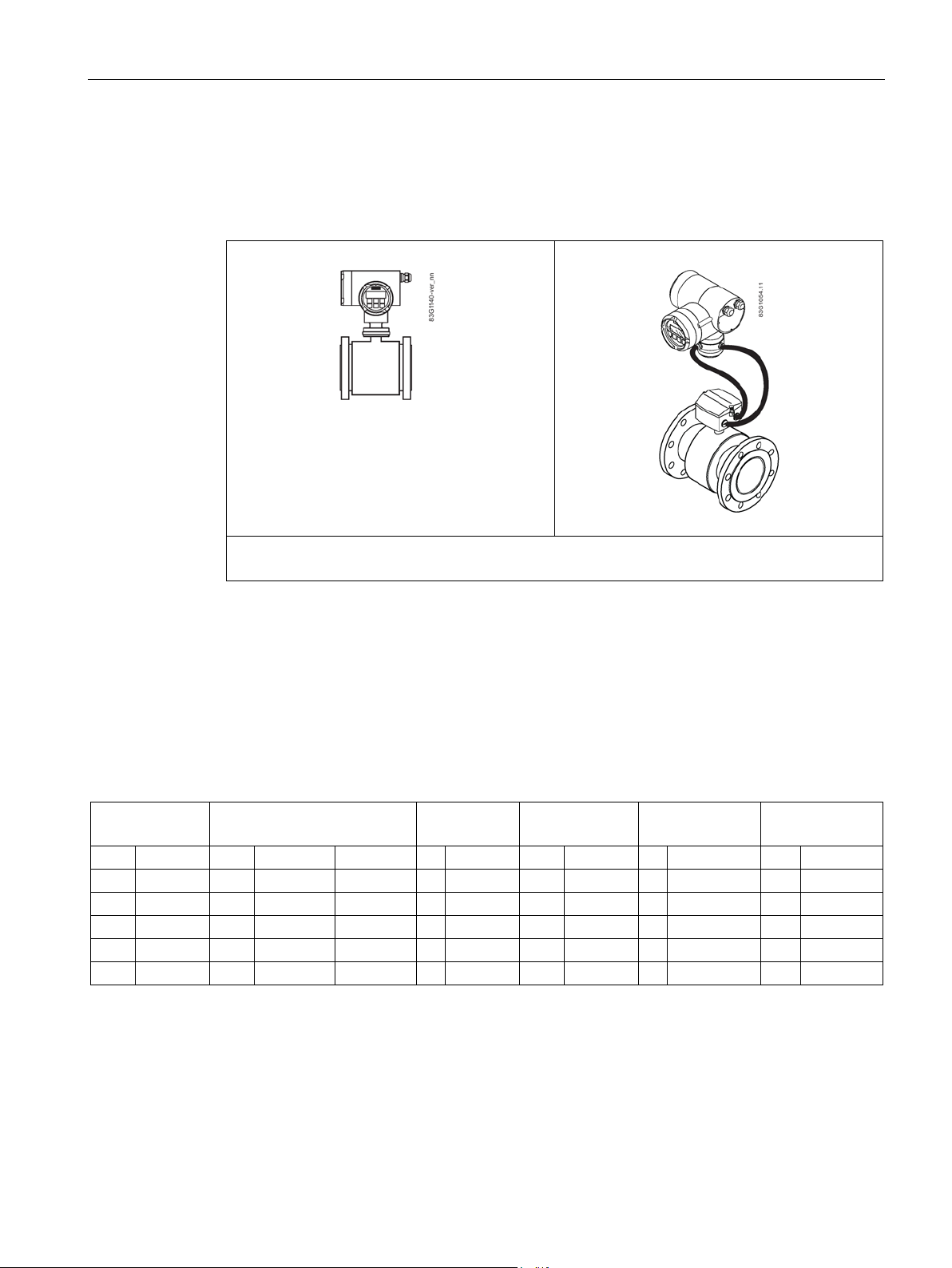
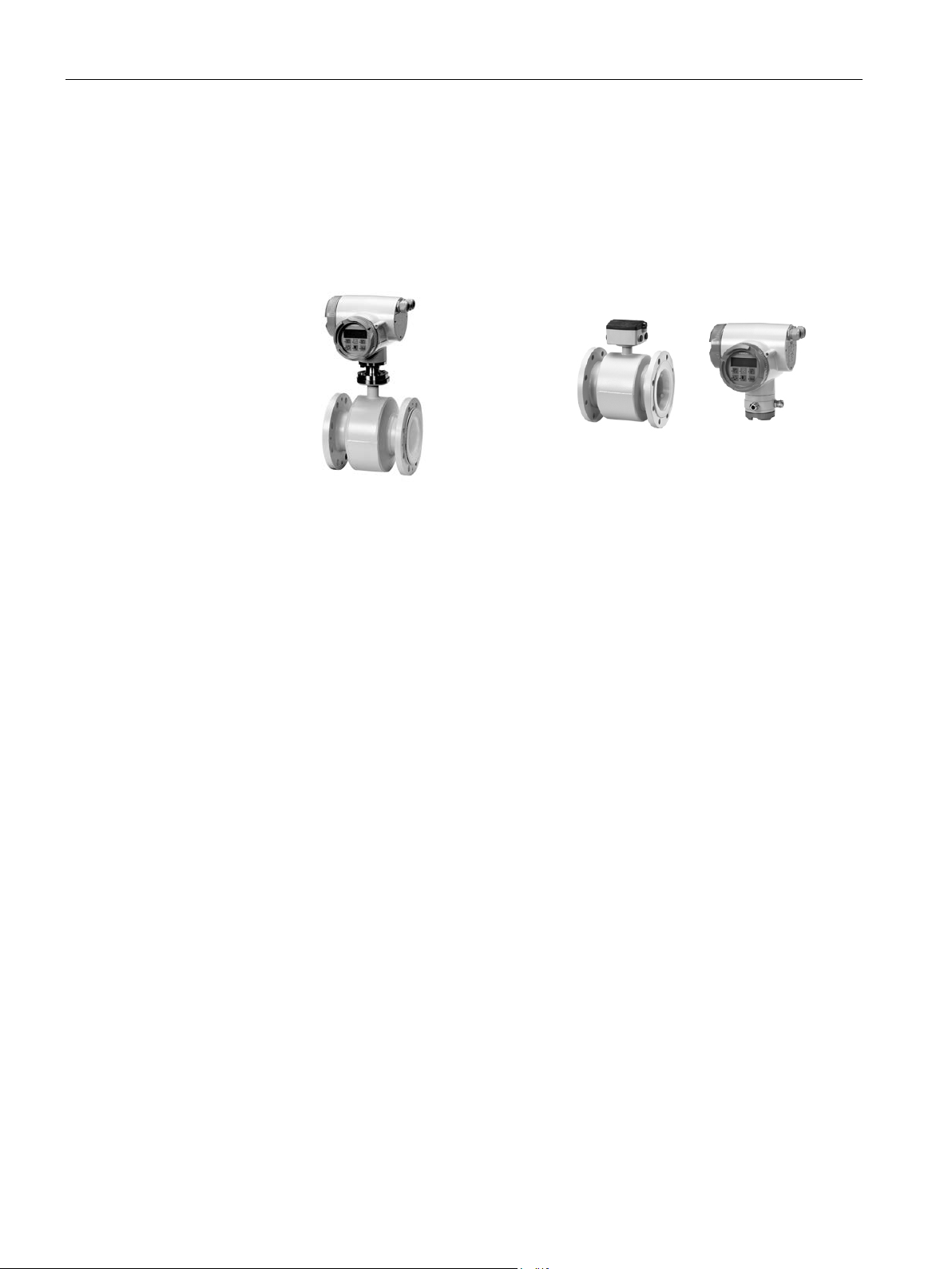
Compact version
Remote version
3.3 Design
The SITRANS F M MAG 6000 I/MAG 6000 I Ex de transmitter is designed for demands in
the process industry. The robust cast aluminum housing provides superb protection, even in
the most harsh industrial environments. Full input and output functionality is given even in
the Ex version.
The transmitter is designed for either compact or remote installation in non-hazardous or
hazardous areas.
Functions:
● Flow rate measurement
● 2 measuring ranges
● Display with 2 totalizers and keypad
● Low flow cut-off
● Analog, pulse/frequence and relay outputs
● Optional: additional digital communication modules
● Error and error log system
● Uni-/bidirectional flow
● Limit switches
● Integrated batch control
MAG 6000 I / MAG 6000 I Ex de transmitter
20 Operating Instructions, 04/2016, A5E02083319-AG

Description
3.4
Features
3.4 Features
● SENSORPROM® memory unit
– All SITRANS F M electromagnetic flowmeters feature a unique SENSORPROM
®
memory unit which stores sensor calibration data as well as transmitter settings for the
lifetime of the product.
– At commissioning the flowmeter commences measurement without any initial
programming.
®
– The factory settings matching the sensor are stored in the SENSORPROM
customer- specified settings are downloaded to the SENSORPROM
®
unit. Also
unit. Should the
transmitter be replaced, the new transmitter will upload all previous settings and
resume measurement without any need for re-programming.
● USM II "Plug & Play" add-on communication modules
USM II - the Universal Signal Module with "Plug & Play" simplicity makes it easy to
access and integrate the flow measurement with almost any control system. It ensures
the flowmeter will be easy to upgrade to new communication platforms in the future, too.
● CAN communication
The transmitter operates internally via an internal CAN communication bus. Signals are
transferred through a signal conditioner to the display module and to/from
internal/external option modules and the dialog module.
● Dialog module
The display unit consists of a 3-line display and a 6-key keypad. The display shows a flow
rate or a totalizer value as a primary reading and can be changed from the factory-set
English to ten other languages. In the Operator menu setup it is possible to configure the
display to show various different menus.
● Output module
The output module converts flow data to analog, digital and relay outputs. The outputs
are galvanically isolated and can be individually set to suit a particular application.
MAG 6000 I / MAG 6000 I Ex de transmitter
Operating Instructions, 04/2016, A5E02083319-AG
21
Description
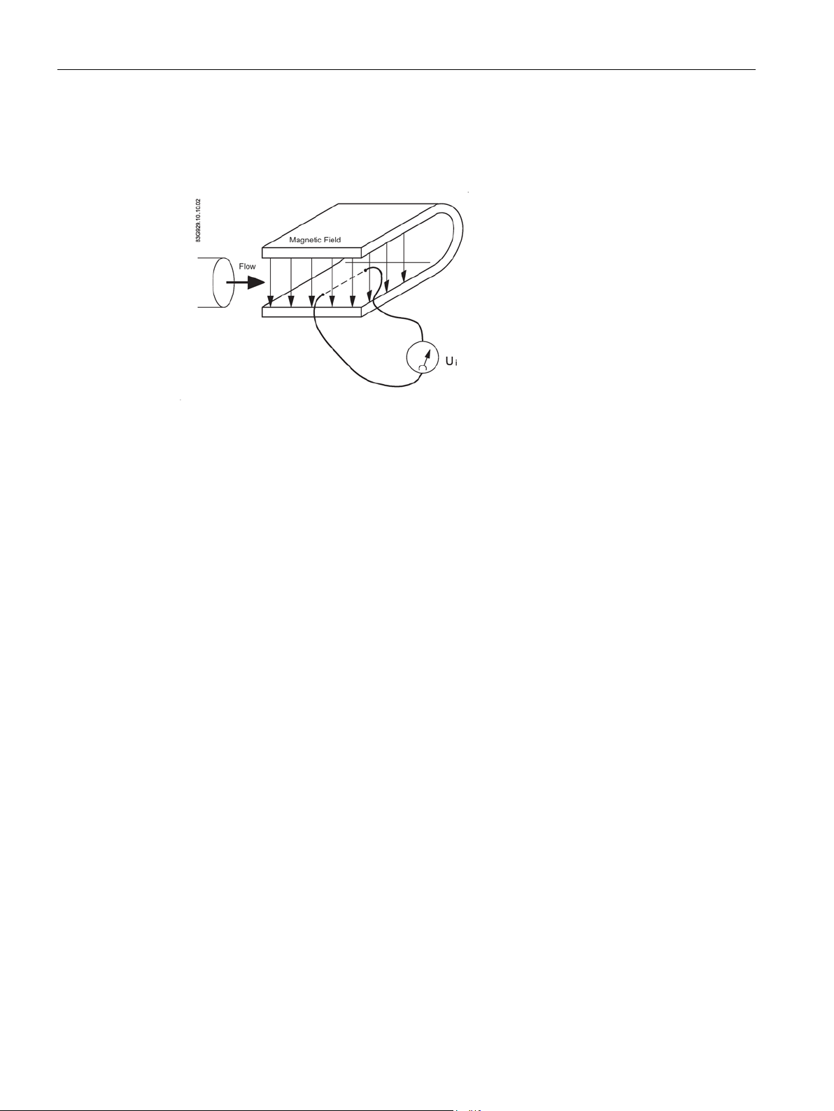
3.5
Theory of operation
Ui = L x B x v
Ui = k x v, the electrode signal is directly proportional to the fluid velocity
3.5 Theory of operation
The flow measuring principle is based on Faraday’s law of electromagnetic induction.
Ui = When an electrical conductor of length L is moved at velocity v, perpendicular to the
lines of flux through a magnetic field of strength B, the voltage Ui is induced at the ends of
the conductor
● Ui = Induced voltage
● L = Conductor length = Inner pipe diameter = k
● B = Magnetic field strength = k
2
1
● v = Velocity of conductor (media)
● k = k
x k2
1
Coil current module generates a pulsating magnetizing current that drives the coils in the
sensor. The current is permanently monitored and corrected. Errors or cable faults are
registered by the self-monitoring circuit.
Input circuit amplifies the flow-proportional induced signal from the electrodes. The input
14
impedance is extremely high: >10
Ω which allows flow measurements on fluids with
conductivities as low as 5 μS/cm. Measuring errors due to cable capacitance are eliminated
due to active cable screening.
Digital signal processor converts the analog flow signal to a digital signal and suppresses
electrode noise through a digital filter. Inaccuracies in the transmitter as a result of long-term
drift and temperature drift are monitored and continuously compensated for via the selfmonitoring circuit. The analog to digital conversion takes place in an ultra low noise ASIC
with 23 bit signal resolution. This has eliminated the need for range switching. The dynamic
range of the transmitter is therefore unsurpassed with a turn down ratio of minimum 3000:1.
MAG 6000 I / MAG 6000 I Ex de transmitter
22 Operating Instructions, 04/2016, A5E02083319-AG
4
4.1
Installation safety precautions
WARNING
High pressure hazard
4.2
Installation conditions
This chapter describes how to install the flowmeter in the compact version as well as in the
remote version.
SITRANS F flowmeters with minimum IP67/NEMA 4X enclosure rating are suitable for indoor
and outdoor installations.
All sensors have an associated SENSORPROM
®
containing all necessary sensor data.
In applications with working pressures/media that can be dangerous to people,
surroundings, equipment or others in case of pipe fracture, we recommend that special
precautions such as special placement, shielding or installation of a pressure guard or a
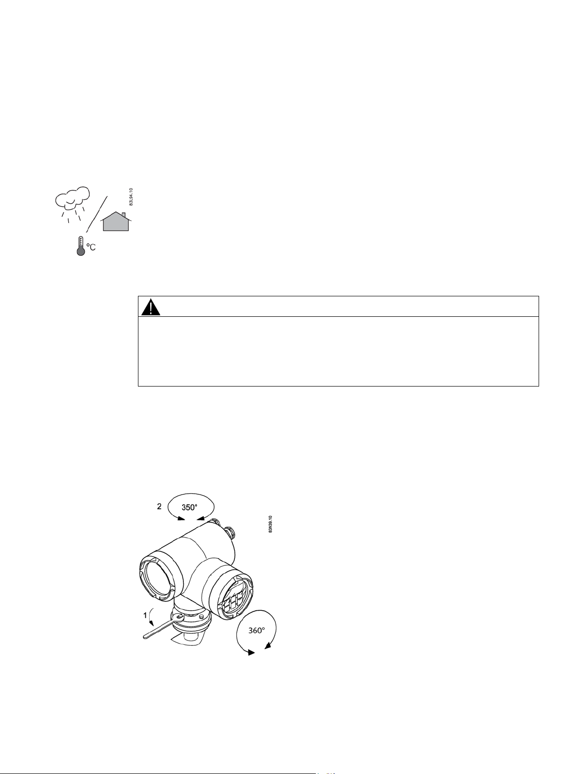
safety valve are taken when the sensor is mounted.
As the transmitter housing and the display can be oriented in all directions, reading and
operating the flowmeter is possible under almost any installation conditions.
MAG 6000 I / MAG 6000 I Ex de transmitter
Operating Instructions, 04/2016, A5E02083319-AG
23
Installing/Mounting
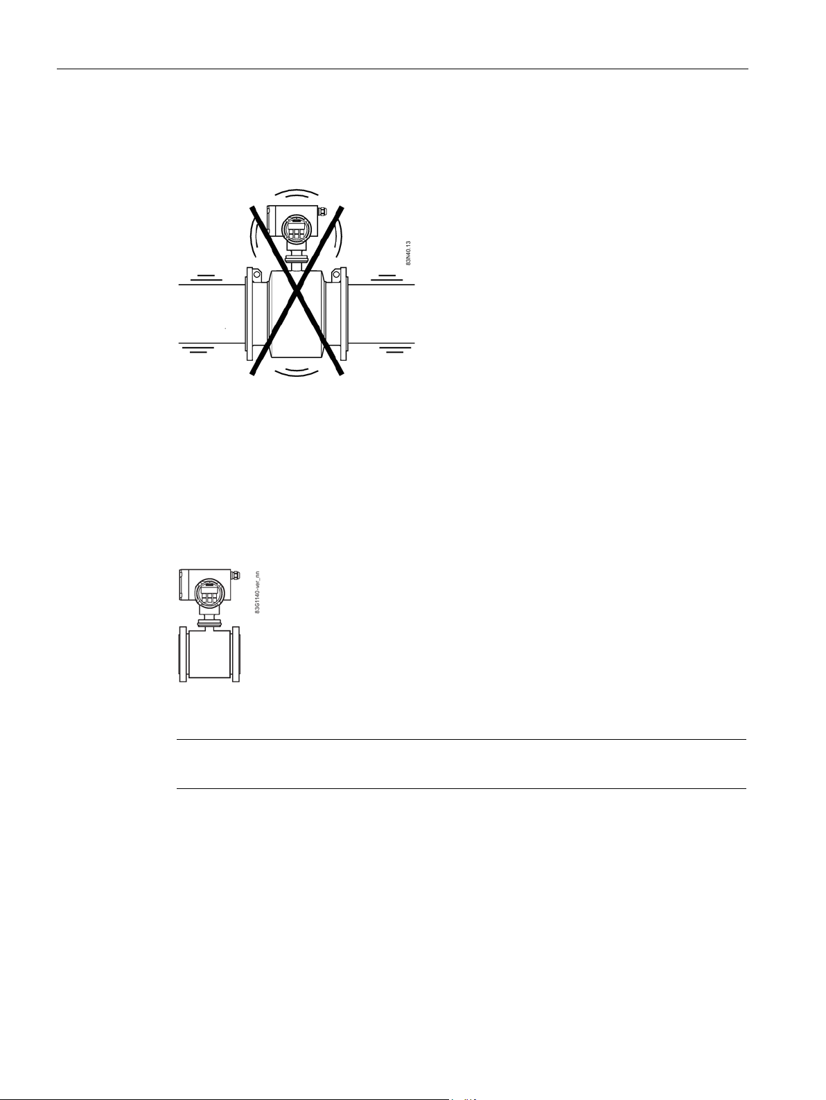
Vibrations
4.3
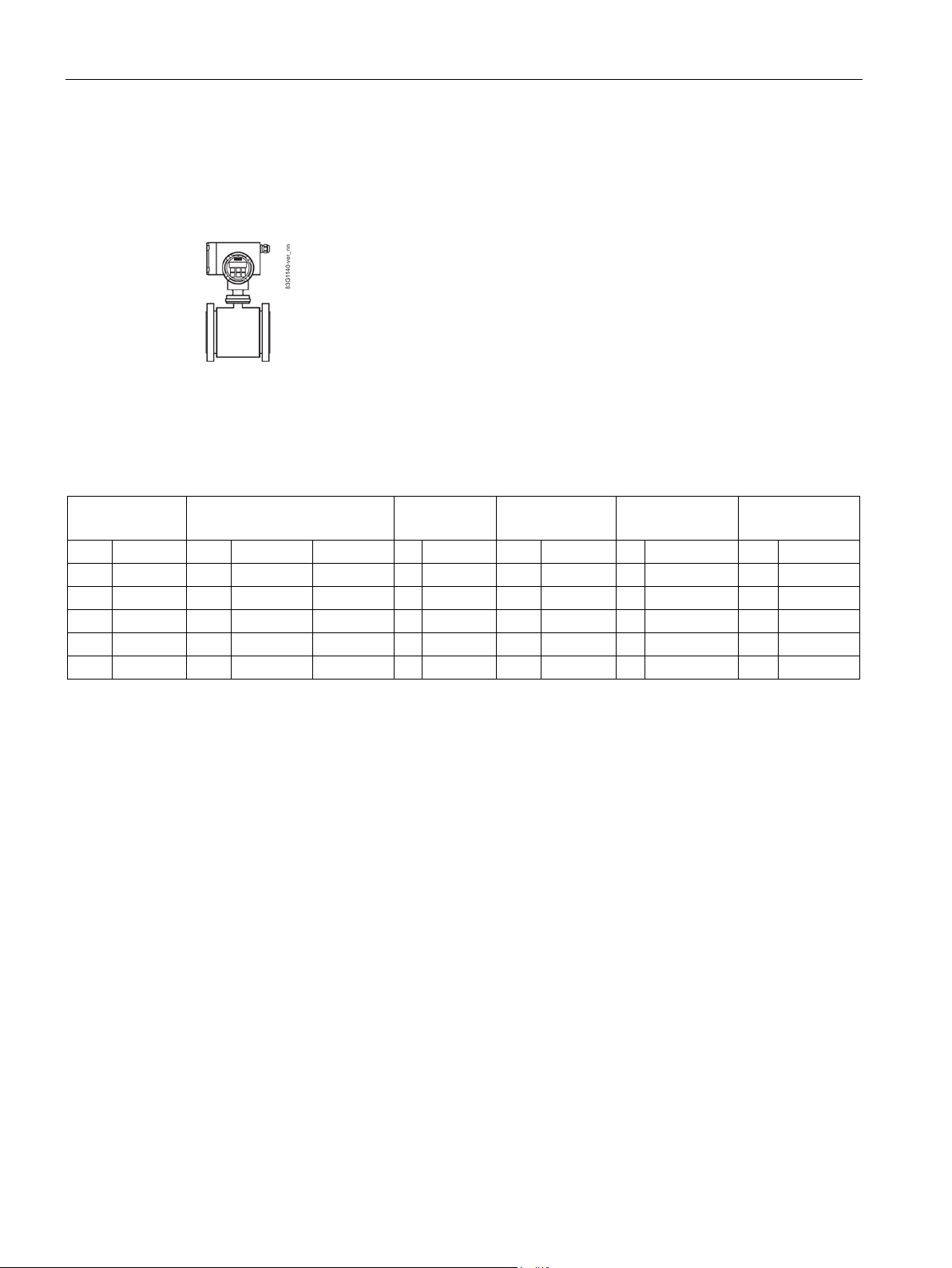
Compact installation
Note
To avoid too high tension on small sizes MAG 1100 sensors, transmitter must be supported.
4.3 Compact installation
To ensure optimum flow measurement, attention should be paid to the following:
Image 4-1 Avoid strong vibrations
In installation with strong vibrations remote installation of the transmitter is recommended.
The flowmeter is delivered with default factory settings and start measuring the flow rate
®
after power-up. The SENSORPROM
Image 4-2 Compact installation
is factory-mounted in the transmitter.
MAG 6000 I / MAG 6000 I Ex de transmitter
24 Operating Instructions, 04/2016, A5E02083319-AG
Installing/Mounting
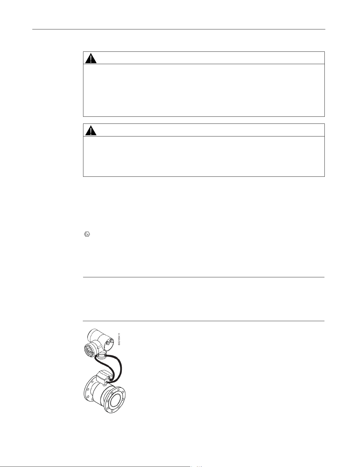
4.4
Remote installation
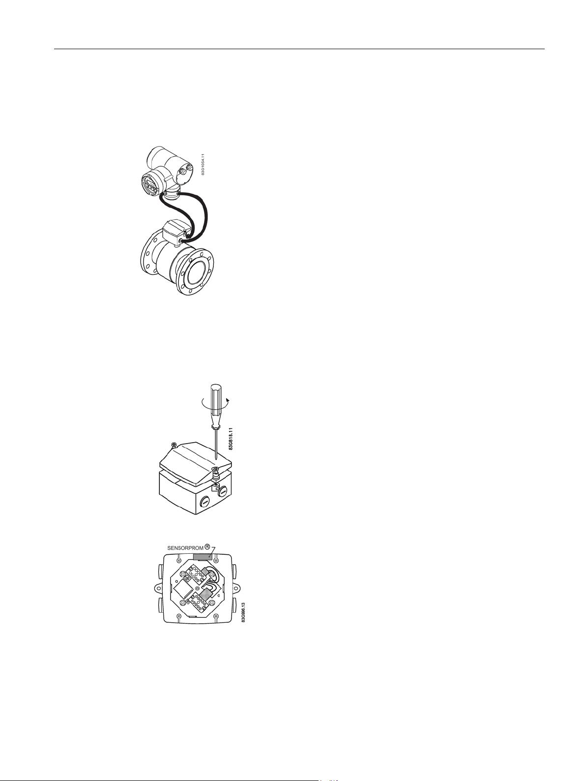
4.4 Remote installation
For remote versions the SENSORPROM® has to be removed from the sensor terminal box
and mounted in the remote transmitter.
Image 4-3 Remote installation
Cable length and type (as described in Cable requirements (Page 68)) must be used.
For installation conditions for sensors, see respective sensor operating instructions.
1. Remove sensor terminal box lid.
2. Remove SENSORPROM
®
unit from sensor terminal box.
MAG 6000 I / MAG 6000 I Ex de transmitter
Operating Instructions, 04/2016, A5E02083319-AG
25
Installing/Mounting
Note
Unscreened cable ends must be kept as short as possible.
Electrode cable and coil cable must be kept separate to prevent interference.
WARNING
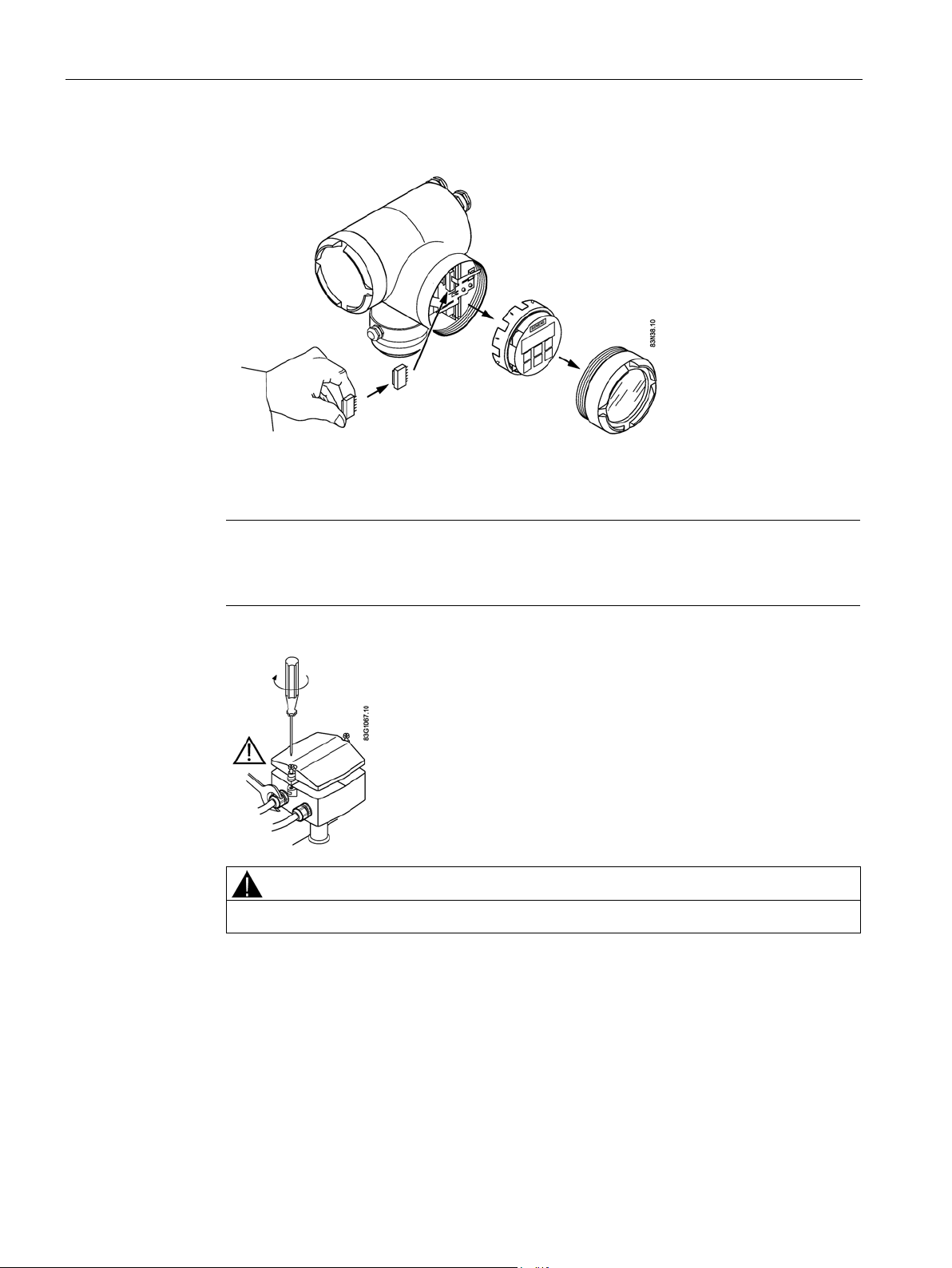
4.4 Remote installation
3. Mount SENSORPROM
®
in remote transmitter.
4. Fit M20 or ½" NPT cable glands on sensor terminal box.
5. Fit and connect electrode and coil cables as described in Connecting (Page 31).
6. Tighten cable glands and lid screws well to obtain optimum sealing.
Mount terminal box lid before power up.
MAG 6000 I / MAG 6000 I Ex de transmitter
26 Operating Instructions, 04/2016, A5E02083319-AG
Installing/Mounting
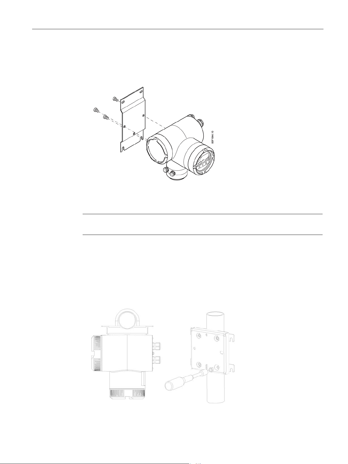
4.4.1
Wall mounting using standard mounting plate
Note
The standard mounting plate is only suitable for wall mounting.
4.4.2
Pipe or wall mounting with assembly bracket
Pipe mounting
4.4 Remote installation
1. Fit the mounting plate on the transmitter using the mounting material provided
2. Mount transmitter with mounting plate on the wall.
Image 4-4 Standard mounting plate
For details on mounting plate, see Dimensions and weight (Page 63).
1. Mount the assembly bracket on the pipe using the fastening brackets
2. Fasten the transmitter with the two screws provided.
Pipe mounting with assembly bracket
MAG 6000 I / MAG 6000 I Ex de transmitter
Operating Instructions, 04/2016, A5E02083319-AG
27
Installing/Mounting
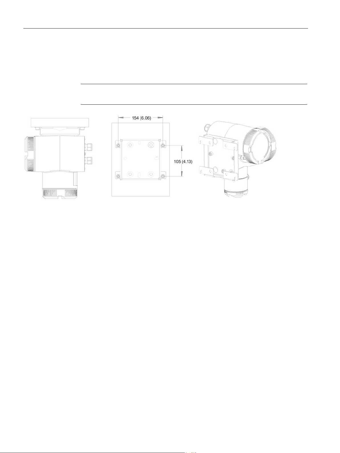
Wall mounting
Note
The fastening brackets and nuts are not needed for wall mounting.
4.4 Remote installation
1. Fasten the assembly bracket to the back of the transmitter
2. Fasten the transmitter and assembly bracket to the wall
Wall mounting with assembly bracket. Dimensions in mm (inch).
MAG 6000 I / MAG 6000 I Ex de transmitter
28 Operating Instructions, 04/2016, A5E02083319-AG
 Loading...