

Page 1
s
INSTRUCTIONS
SITRANS F M
Electromagnetic flowmeter
type MAG 1100, DN 2 - DN 100 1/12" - 4"
ENGLISH
DEUTSCH
FRANÇAIS
DANSK
Introduction
083R9017
Dimensions and
weight
Important note!
for compact installations
with the MAG 6000I,
transmitter to be supported to avoid tension
on sensor part.
Siemens Flow Instruments SITRANS F M electromagnetic flowmeters consist of a sensor and a
transmitter. These instructions only describe the sensor installation. For further information on the
transmitter installation, please refer to the SITRANS F M handbook.
Technical Documentation (handbooks, instructions, manuals etc.) on the complete product
range SITRANS F can be found on the internet/intranet on the following links:
English:
http://www4.ad.siemens.de/WW/view/en/10806951/133300
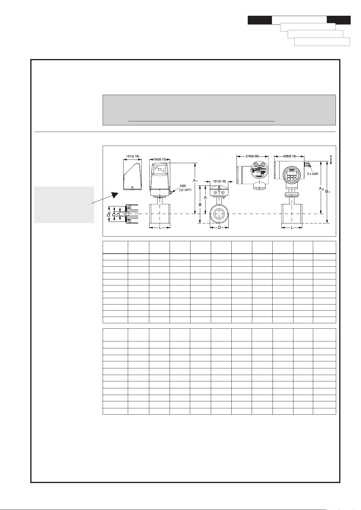
MAG 1100/6000, MAG 1100/5000 and MAG 1100/6000I, compact/separate
DN A1)B1)A2/A
[mm] [mm] [mm] [mm] [mm] [mm] [mm] [mm] [mm] [kg]
2 161 186 315 340 48.7 2 17.3 34 2.2
3 161 186 315 340 48.7 3 17.3 34 2.2
6 161 186 315 340 48.7 6 17.3 34 2.2
10 161 186 315 340 48.7 10 10 13.6 34 2.2
15 161 186 315 340 48.7 15 16 17.3 40 2.2
25 169 201 323 354 63.5 25 26 28.5 56 2.7
40 179 221 333 375 84.0 40 38 43.4 75 3.4
50 188 239 342 393 101.6 50 50 54.5 90 4.2
65 198 258 351 412 120.9 65 66 68.0 112 5.5
80 204 270 357 424 133.0 80 81 82.5 124 7.0
100 217 296 370 450 159.0 100 100 107.1 145 10.0
4
)B1DD
2
2
)Di (PFA) D
i
p
DGWeight3)
083R9017
Size A1)B1)A2/A
1
1
1
3
1
1½ 7.05 8.70 13.11 14.76 3.31 1.57 1.50 1.71 2.95 7.5
2½ 7.80 10.16 13.82 16.22 4.76 2.56 2.60 2.68 4.41 12
1
) 14.5 mm/0.57" shorter when the AISI terminal box is used. (high temperature 200°C (390°F)).
2
) DN 2-3 Zirconium (Zr02), DN 6-100/1/4"-4" Ceramic (Al2O3).
3
) With transmitter MAG 5000 or MAG 6000 installed, weight is increased by approximately 0.8 kg (1.8 lb).
4
)A2 is 3 mm(0.12") shorter than A1.
[inch] [inch] [inch] [inch] [inch] [inch] [inch] [inch] [inch] [lbs]
/
12
/
/
/
/
1 6.66 7.92 12.72 13.94 2.50 0.98 1.02 1.12 2.20 4.9
2 7.40 9.41 13.47 15.47 4.00 1.97 1.97 2.15 3.54 9.2
3 8.03 10.63 14.06 16.70 5.24 3.15 3.19 3.25 4.88 15
4 8.54 11.65 14.57 17.72 6.26 3.94 3.94 4.22 5.91 22
6.34 7.33 12.40 13.39 1.92 0.08 0.68 1.34 4.8
6.34 7.33 12.40 13.39 1.92 0.12 0.68 1.34 4.8
8
6.34 7.33 12.40 13.39 1.92 0.24 0.68 1.34 4.8
4
6.34 7.33 12.40 13.39 1.92 0.39 0.39 0.53 1.34 4.8
8
6.34 7.33 12.40 13.39 1.92 0.59 0.63 0.68 1.57 4.8
2
4
)B1DD
2
2
)Di(PFA) D
i
p
DGWeight3)
SFIDK.PI.027.G7.52Order no.: FDK-521H0928
Page 2
SITRANS F M Electromagnetic flowmeter type MAG 1100, DN 2 - DN 100, 1/12" - 4"
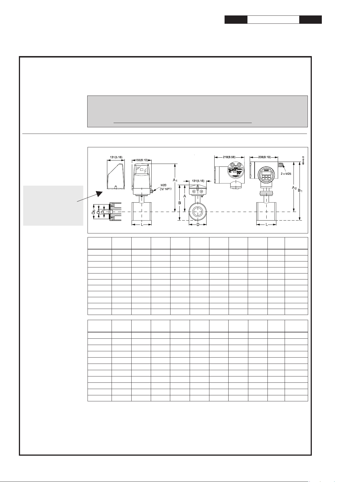
Dimensions and weight
(continued)
The total build-in length "L" [mm/[inch]] depends on the gasket selected.
Size EPDM Graphite PTFE (Teflon) Without gasket Earthing ring
DN Inch [mm] [inch] [mm] [inch] [mm] [inch] [mm] [inch] [mm] [inch]
1
2
2 ...10
/
64 2.52 66 2.60 70 2.75 64 2.52 77 3.03
12
1)
1
/
...3/864 2.52 66 2.60 70 2.75 64 2.52 77 3.03
12
15 ½ 65 2.56 66 2.60 70 2.75 64 2.52 77 3.03
25 1 80 3.15 81 3.19 85 3.35 79 3.10 92 3.62
40 1½ 95 3.74 96 3.78 100 3.94 94 3.70 107 4.21
50 2 105 4.13 106 4.17 110 4.33 104 4.05 117 4.61
65 2½ 130 5.12 131 5.15 135 5.31 129 5.05 142 5.60
80 3 155 6.10 156 6.14 160 6.30 154 6.00 167 6.57
100 4 185 7.28 186 7.31 190 7.48 184 7.20 197 7.76
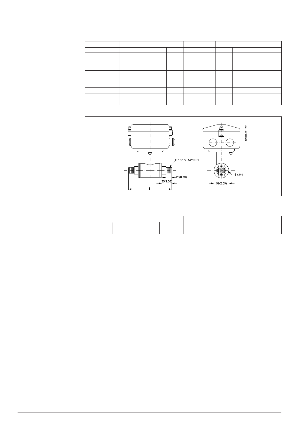
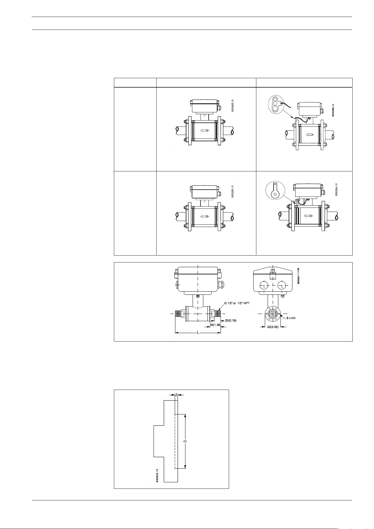
Sensor MAG 1100 DN2...10 (1/12”...3/8") with adaptors
The MAG 1100 DN 2, 3, 6 and DN 10 are prepared for G ½" (ISO) or ½" NPT pipe connection.
The length "L" varies dependent on the gasket choice.
Without gasket EPDM Graphite Teflon
[mm] [inch] [mm] [inch] [mm] [inch] [mm] [inch]
150 5.9 150 5.9 152 6.0 156 6.1
Important note:
For compact installation with the MAG 6000 I, transmitter to be supported to avoid tension on sensor
part.
2
Page 3
SITRANS F M Electromagnetic flowmeter type MAG 1100, DN 2 - DN 100, 1/12" - 4"
Installation, general
Reading and operating the flowmeter is possible under almost any installation conditions
because the display can be oriented in relation
to the sensor. To ensure optimum flow measurement attention should be paid to the following:
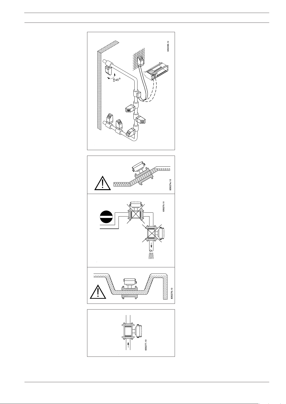
The sensor must always be completely full
with liquid.
Therefore avoid:
• Installation at the highest point in the pipe
system
• Installation in vertical pipes with free outlet
For partially filled pipes or pipes with downward flow and free outlet the flowmeter should
be located in a U-tube.
Installation in vertical pipes
Recommended flow direction: upwards. This
minimizes the effect on the measurement of
any gas/air bubbles in the liquid.
3
Page 4
SITRANS F M Electromagnetic flowmeter type MAG 1100, DN 2 - DN 100, 1/12" - 4"
Installation, general
(continued)
Installation in horizontal pipes
The sensor must be mounted as shown in the
upper figure. Do not mount the sensor as
shown in the lower figure. This will position the
electrodes at the top where there is possibility
for air bubbles and at the bottom where there
is possibility for mud, sludge, sand etc.
If using empty pipe detection the sensor can be
tilted 45°, as shown in the upper figure.
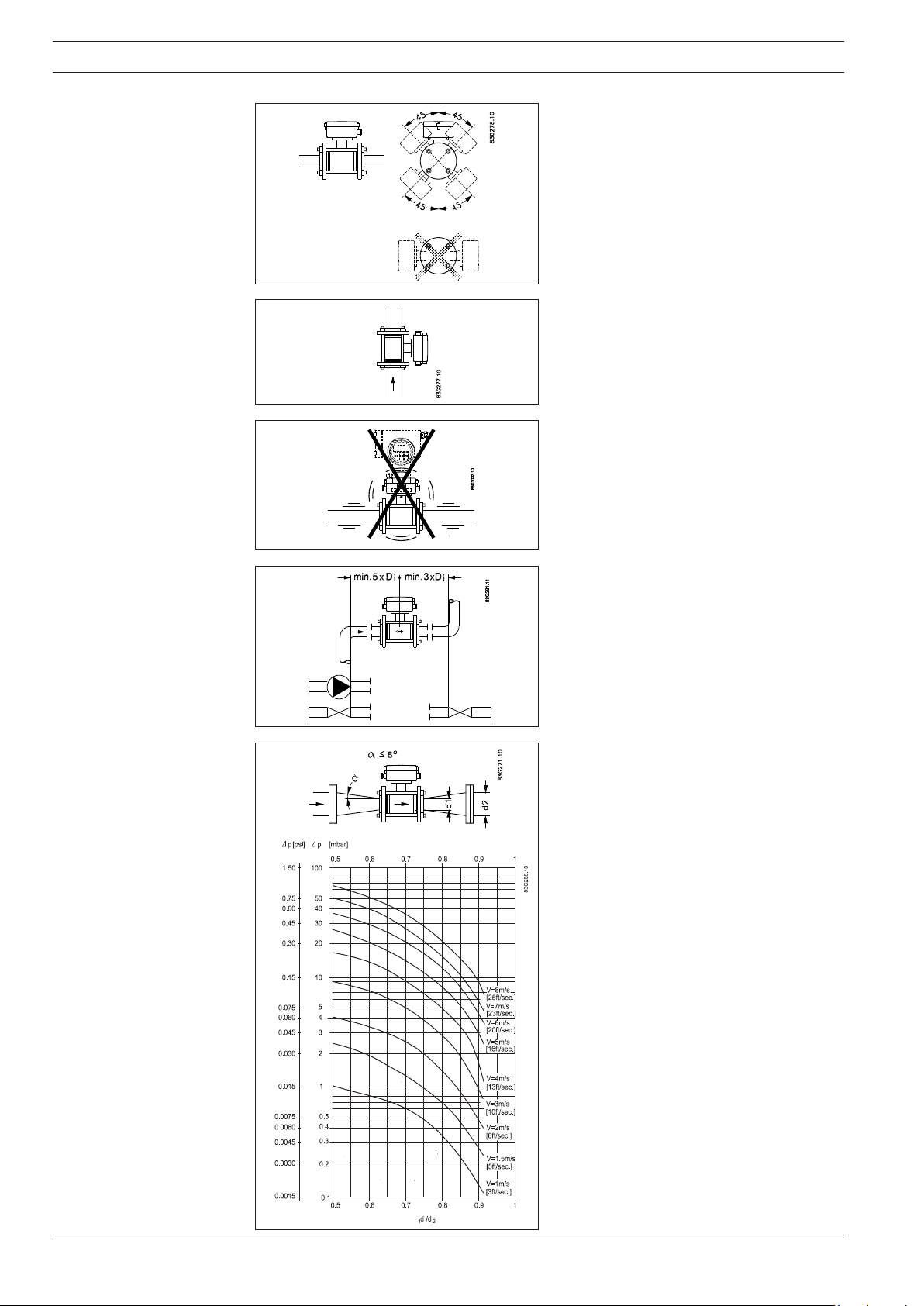
Measuring abrasive liquids and liquids containing particles
Recommended installation is in a vertical/
inclined pipe to minimize the wear and deposits in the sensor.
Avoid vibrations!
Inlet and outlet conditions
To achieve accurate flow measurement it is
essential to have straight lengths of inlet and
outlet pipes and a certain distance between
pumps and valves.
It is also important to centre the flowmeter in
relation to pipe flanges and gaskets.
Installation in large pipes
The flowmeter can be installed between two
reducers (e.g. DIN 28545). Assuming that at 8°
the following pressure drop curve applies. The
curves are applicable to water.
Example:
A flow velocity of 3 m/s (V) in a sensor with a
diameter reduction from DN 100 to DN 80
= 0.8) gives a pressure drop of 2.9 mbar.
(d
1/d2
4
Page 5
SITRANS F M Electromagnetic flowmeter type MAG 1100, DN 2 - DN 100, 1/12" - 4"
Installation, general
(continued)
Potential equalization
To obtain optimum results from the measuring system the sensor’s chassis point/housing must
have the same electrical potential as the liquid being measured.
Depending on the type of gasket selected (graphite, EPDM or PTFE) and application, this can
be achieved as follows:
Graphite gaskets EPDM or PTFE gaskets
Electrically
conductive
piping
A: Potential equalization with electri-
cally conductive graphite gaskets
Electrically
non-conductive
piping
B: Potential equalization using earth
strap supplied.
C: Potential equalization with electri-
cally conductive graphite gaskets
D: Potential equalization using sepa-
rate potential equalization ring
The sensors DN 2, 3, 6 and DN 10 can also be mounted between two adapter flanges. In this
way the potential equalization with the liquid occurs automatically.
NOTE:
Special attention must be paid to piping systems with cathodic protection.
See SITRANS F M handbook.
For applications where high accuracy is
required, it will be advantageous to use
recessed flanges as shown in the drawing.
NB
To obtain optimum measuring accuracy and
the necessary tightness, it is important that the
sensor gaskets and the flange centre lines are
merging and that the connection flanges have
been mounted at right angles to the pipe.
The connection flanges must be parallel.
5
Page 6
SITRANS F M Electromagnetic flowmeter type MAG 1100, DN 2 - DN 100, 1/12" - 4"
Installation
Tightening
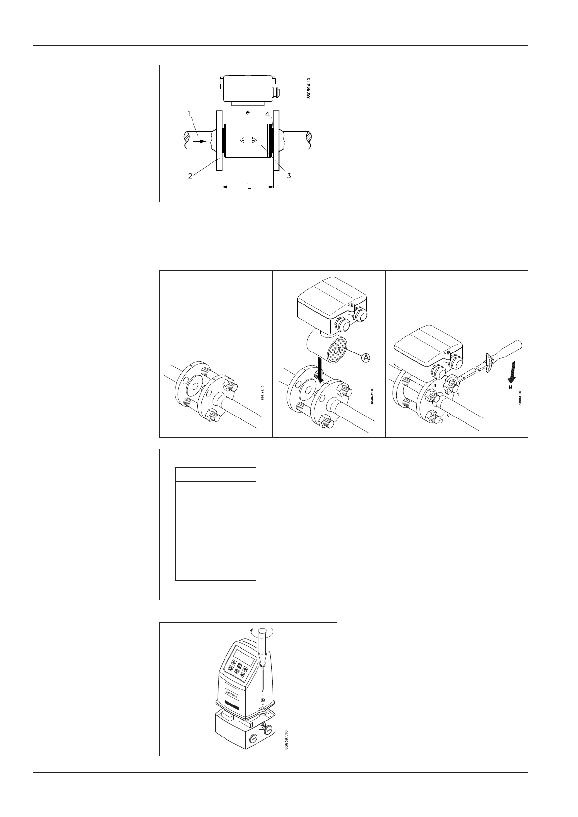
The design of the sensor MAG 1100 allows for
bi-directional flow. Dimension L is given in the
previous table.
The arrow at the sensor indicates recommended
flow direction (the meter has been calibrated
with flow in arrow direction "+").
1. Existing pipe
2. Flange
3. Sensor
4. Gaskets
L. Sensor length incl. gaskets
First place three stay-bolts to locate the sensor, see a. These should be tightened gently, making
sure that each gasket fits exactly into its recess at either end of the sensor, see b.
The remaining flange bolts can now be inserted and tightened using about 25% of the actual
tightening torque, see table d.
ac
b
Installation of the cover or
transmitter on the terminal box
d
DN MA [Nm]
2
3
6
10
15
25
40
50
65
80
100
10 Nm ~ 1 kpm
13
13
13
13
16
30
54
90
90
90
115
The bolts must be tightened using up to 50% of the max.
tightening torque for the pipe dimensions stated. The max.
tightening torque for different size pipes is given in the table d.
The bolts must now be cross-tightened in the sequence shown
in c, using up to 100% torque.
1. Mount the cover or the transmitter on the
terminal box.
2. It is important that the screws are firmly
tightened (4 Nm). Use a large screwdriver
fitting into the screw slot.
6
Page 7
SITRANS F M Electromagnetic flowmeter type MAG 1100, DN 2 - DN 100, 1/12" - 4"
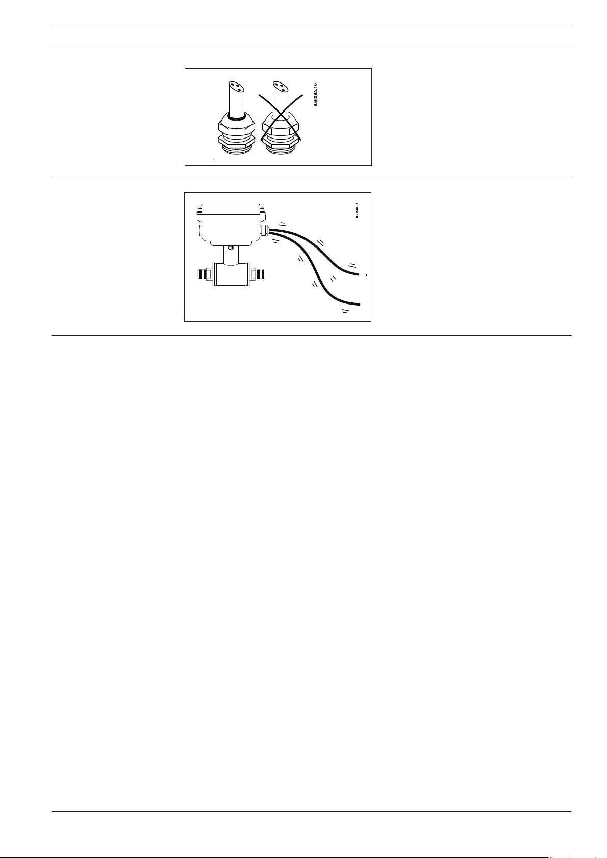
Installation, cable Tighten the cable glands and the cable entries
Installation, low conductivity and high vibration
levels of cables, MAG
1100 DN 2+3
Manufacturer’s design
and safety statement
1. Responsibility for the choice of lining and electrode materials with regard to their abrasion
and corrosion resistance lies with the purchaser; the effect of any change in process medium
during the operating life of the flowmeter should be taken into account. Incorrect selection
of lining and/or electrode materials could lead to a failure of the flowmeter.
2. It is the responsibility of the user to ensure that stresses and loading caused by earthquakes,
traffic, high winds and fire damage are taken into account during installation, when appropriate. These forces are not taken into account during flowmeter design.
3. It is the responsibility of the user to ensure that the flowmeter is installed such that it does not
act as a focus for pipeline stresses. External loadings are not taken into account during
flowmeter design.
4. During operation do not exceed the pressure and/or temperature ratings indicated on the data
label or in the installation instructions.
5. It is the responsibility of the user to ensure that all installations include over pressure protection,
means for draining/venting, and that adequate protection is provided to minimise
any risk of contact with hot surfaces.
6. Under the Pressure Equipment Directive this product is a pressure accessory, and not
approved for use as a safety accessory, as defined by the Pressure Equipment Directive.
7. Removal of the terminal box except by Siemens Flow Instruments or their approved agents
will invalidate the PED conformity of the product.
In accordance with the Pressure Equipment Directive (97/23/EC)
to obtain optimum sealing. The cable entry
gasket must obtain firm contact with the cable.
For sensors DN 2+3 in applications with low
conductivity and high vibration level of cables
use low noise coax electrode cable.
7
Page 8
s
INSTRUCTIONS
DEUTSCH
SITRANS F M
Magnetisch induktiver Durchflussmesser
Typ MAG 1100, DN 2 - DN 100 1/12" - 4"
Einführung
083R9017
Abmessungen und
Gewichte
Wichtiger Hinweis:
Bei Kompakteinbau mit
dem MAG 6000 I ist der
Messumformer abzustützen, um Zugspannung
auf den Messaufnehmer
zu vermeiden.
Siemens Flow Instruments SITRANS F M magnetisch-induktive Durchflussmesser bestehen aus
einem Messaufnehmer und einem Messumformer. Diese Instruktion beschreibt nur die Montage
des Messaufnehmers. Für weitere Informationen über die Montage des Messumformers, siehe
bitte das SITRANS F M Produkthandbuch.
Technische Unterlagen (Handbücher, Instruktionen, Betriebsanleitung usw.) des
kompletten Warenangebotes von SITRANS F sind auf dem Internet/Intranet unter folgenden
Links verfügbar
Deutsch:
http://www4.ad.siemens.de/WW/view/de/10806951/133300
MAG 1100/6000, MAG 1100/5000 und MAG 1100/6000I, kompakte/getrennte Montage
083R9017
DN A1)B1)A2/A
10 161 186 315 340 48,7 10 10 13,6 34 2,2
15 161 186 315 340 48,7 15 16 17,3 40 2,2
25 169 201 323 354 63,5 25 26 28,5 56 2,7
40 179 221 333 375 84,0 40 38 43,4 75 3,4
50 188 239 342 393 101,6 50 50 54,5 90 4,2
65 198 258 351 412 120,9 65 66 68,0 112 5,5
80 204 270 357 424 133,0 80 81 82,5 124 7,0
100 217 296 370 450 159,0 100 100 107,1 145 10,0
Size A1)B1)A2/A
1
/
1
1
3
1
1½ 7,05 8,70 13,11 14,76 3,31 1,57 1,50 1,71 2,95 7,5
2½ 7,80 10,16 13,82 16,22 4,76 2,56 2,60 2,68 4,41 12
1
) 13 mm kürzer bei Gebrauch des AISI-Klemmkastens (Hochtemperatur 200°C).
2
) DN 2-3 Zirkonium (Zr02), DN 6-100 Keramik (Al2O3).
3
) Bei eingebautem Messumformer MAG 5000 oder MAG 6000 erhöht sich das Gewicht um ca. 0,8 kg.
4
)A2 ist 3 mm(0.12") kürzer als A1.
[mm] [mm] [mm] [mm] [mm] [mm] [mm] [mm] [mm] [kg]
2 161 186 315 340 48,7 2 17,3 34 2,2
3 161 186 315 340 48,7 3 17,3 34 2,2
6 161 186 315 340 48,7 6 17,3 34 2,2
[inch] [inch] [inch] [inch] [inch] [inch] [inch] [inch] [inch] [lbs]
12
/
/
/
/
1 6,66 7,92 12,72 13,94 2,50 0,98 1,02 1,12 2,20 4,9
2 7,40 9,41 13,47 15,47 4,00 1,97 1,97 2,15 3,54 9,2
3 8,03 10,63 14,06 16,70 5,24 3,15 3,19 3,25 4,88 15
4 8,54 11,65 14,57 17,72 6,26 3,94 3,94 4,22 5,91 22
6,34 7,33 12,40 13,39 1,92 0,08 0,68 1,34 4,8
6,34 7,33 12,40 13,39 1,92 0,12 0,68 1,34 4,8
8
6,34 7,33 12,40 13,39 1,92 0,24 0,68 1,34 4,8
4
6,34 7,33 12,40 13,39 1,92 0,39 0,39 0,53 1,34 4,8
8
6,34 7,33 12,40 13,39 1,92 0,59 0,63 0,68 1,57 4,8
2
4
)B1DD
2
4
)B1DD
2
2
)Di (PFA) D
i
2
)Di(PFA) D
i
DGGewicht3)
p
DGGewicht3)
p
SFIDK.PI.027.G7.52
Page 9

SITRANS F M Magnetisch induktiver Durchflussmesser Typ MAG 1100, DN 2 - DN 100, 1/12" - 4"
Abmessungen und
Gewichte
(Fortsetzung)
Die Gesamteinbaulänge "L" [mm/[inch]] hängt von der Wahl der Dichtung ab.
Size EPDM Graphit PTFE (Teflon) Ohne Dichtung Erdungsflansch
DN Inch [mm] [inch] [mm] [inch] [mm] [inch] [mm] [inch] [mm] [inch]
1
2
2 ,,10
/
64 2,52 66 2,60 70 2,75 64 2,52 77 3,03
12
1)
1
/
,,3/864 2,52 66 2,60 70 2,75 64 2,52 77 3,03
12
15 ½ 65 2,56 66 2,60 70 2,75 64 2,52 77 3,03
25 1 80 3,15 81 3,19 85 3,35 79 3,10 92 3,62
40 1½ 95 3,74 96 3,78 100 3,94 94 3,70 107 4,21
50 2 105 4,13 106 4,17 110 4,33 104 4,05 117 4,61
65 2½ 130 5,12 131 5,15 135 5,31 129 5,05 142 5,60
80 3 155 6,10 156 6,14 160 6,30 154 6,00 167 6,57
100 4 185 7,28 186 7,31 190 7,48 184 7,20 197 7,76
Sensor MAG 1100 DN2...10 (1/12”...3/8") mit Adaptern
MAG 1100 DN 2, 3, 6 und DN 10 sind für den Anschluss an G ½" (ISO) oder ½" NPT-Rohrleitungen
vorbereitet.
Die Gesamteinbaulänge "L" [mm] hängt von der Wahl der Dichtung ab.
Ohne Dichtung EPDM Graphit Teflon
[mm] [inch] [mm] [inch] [mm] [inch] [mm] [inch]
150 5.9 150 5.9 152 6.0 156 6.1
Wichtiger Hinweis:
Bei Kompakteinbau mit dem MAG 6000 I ist der Messumformer abzustützen, um Zugspannung
auf den Messaufnehmer zu vermeiden.
9
Page 10

SITRANS F M Magnetisch induktiver Durchflussmesser Typ MAG 1100, DN 2 - DN 100, 1/12" - 4"
Einbau, allgemein
Der Durchflussmesser kann in jeder Einbaulage abgelesen werden, da die Anzeige drehbar ist und in jeder beliebigen Position im
Verhältnis zum Messaufnehmer eingebaut
werden kann. Die endgültige Position sollte
vor der Montage festgelegt werden. Um optimale Messergebnisse zu sichern, sind folgende Hinweise zu beachten:
Der Messaufnehmer muss immer vollständig
gefüllt sein.
Vermeiden Sie:
• Einbau an höchster Stelle des Rohrsystems
• Einbau in einer senkrechten Rohrleitung mit
freiem Ablauf.
Ist eine nur teilweise gefüllte Rohrleitung oder
der freie Ablauf nicht zu vermeiden, sollte der
Durchflussmesser gedükert werden.
Einbau in einer senkrechten Rohrleitung
Empfohlene Strömungsrichtung: von unten
nach oben. Dadurch werden ungenaue
Messergebnisse, verursacht durch Gas- bzw.
Luftblasen im Medium, vermieden.
10
Page 11

SITRANS F M Magnetisch induktiver Durchflussmesser Typ MAG 1100, DN 2 - DN 100, 1/12" - 4"
Einbau, allgemein
(Fortsetzung)
Einbau in einer waagerechten Rohrleitung
Der Messaufnehmer ist wie nebenstehend in
der oberen Abbildung gezeigt zu montieren.
Wegen der Lage der Elektroden oben (hier
können Luftblasen entstehen) und unten (eventuelle Ansammlung von Schlamm, Sand usw.)
darf die Montage nicht wie in der unteren
Abbildung gezeigt erfolgen. Wird die Leerlaufüberwachung aktiviert, um einen leeren Messaufnehmer zu melden, dürfen Messaufnehmer
und Mess-umformer nicht mehr als 45 bis 60°
gedreht werden, siehe obere Abbildung.
Messen von verunreinigten bzw. abrasiven
Medien
In diesem Fall wird der Einbau in einer senkrechten bzw. schrägen Rohrleitung empfohlen, um Verschleiß bzw. Ablagerungen so weit
wie möglich zu vermeiden.
Vermeiden Sie Vibrationen!
Ein- und Auslauf
Genaue Messwerte können nur dann erzielt
werden, wenn ausreichend große gerade Einund Auslaufstrecken sowie genügender Abstand nach Pumpen, Ventilen o. ä. eingehalten
werden.
Außerdem muss der Durchflussmesser mittig
zu den Flanschen und Dichtungen des Rohrsystems eingebaut werden.
Einbau in einer Rohrleitung mit großem
Durchmesser
Falls notwendig, kann der Durchflussmesser
auch zwischen zwei Reduzierstücken, z. B.
nach DIN 28545 eingebaut werden. Unter der
Voraussetzung, dass α
< 8° gilt nebenstehen-
des Druckverlustdiagramm (Medium: Wasser).
Beispiel:
Eine Durchflussgeschwindigkeit von V = 3 m/
s in einem Messaufnehmer mit einer Durchmesserreduktion von DN 100 auf DN 80 (d
= 0,8) verursacht einen Druckabfall von 2,9
1/d2
mbar.
11
Page 12

SITRANS F M Magnetisch induktiver Durchflussmesser Typ MAG 1100, DN 2 - DN 100, 1/12" - 4"
Einbau, allgemein
(Fortsetzung)
Potentialausgleich
Optimale Messergebnisse lassen sich nur dann erzielen, wenn das Messaufnehmergehäuse
und das zu messende Medium das gleiche elektrische Potential haben.
Abhängig von der gewählten Dichtung (Graphit, EPDM oder Teflon) und der Anwendung wird dies
wie folgt erreicht:
Graphitdichtung EPDM- oder Teflondichtung
Elektrisch
leitendes
Rohrsystem
A: Potentialausgleich über elektrisch
leitende Graphitdichtungen
Elektrisch nicht
leitendes
Rohrsystem
B: Potentialausgleich über den
mitgelieferten Hilfserder
C: Potentialausgleich über elektrisch
leitende Graphitdichtungen
D: Potentialausgleich über den
zusätzlich zu bestellenden Potentialausgleichsflansch
Die Messaufnehmer DN 2, 3, 6 und DN 10 können auch zwischen zwei Prozessanschlüssen
montiert werden. Der Potentialausgleich mit dem Medium erfolgt dann automatisch über diese
Prozessanschlüsse und das angrenzende Rohr.
Hinweis:
Bei Rohrsystemen mit Kathodenschutz gelten folgende besondere Regeln:
Siehe SITRANS F M Produkthandbuch.
Für Anwendungen bei denen hohe Genauigkeit gefordert wird, ist es vorteilhaft Gegenflansche wie abgebildet einzusetzen.
12
NB
Zur Erreichung der optimalen Messgenauigket
und Stabilität ist es wichtig, dass die Dichtungen sowie die Flanschschnittlinie übereinstimmen.
Die Verbindungsflansche müssen im rechten
Winkel zum Messrohr und parallel zueinander
angebracht werden.
Page 13

SITRANS F M Magnetisch induktiver Durchflussmesser Typ MAG 1100, DN 2 - DN 100, 1/12" - 4"
Installation
Anziehen
Die Einbaurichtung des Messaufnehmers kann
beliebig gewählt werden.
Die Einbaulänge L der Messaufnehmers ist aus
der umstehende Tabelle ersichtlich.
Der Pfeil am Messaufnehmer zeigt die empfohlene Durchflussrichtung an (Das Gerät wurde in
Pfeilrichtung "+" kalibriert).
1. Rohrleitung
2. Flansch
3. Messaufnehmer
4. Dichtung
L. Einbaulänge mit Dichtungen
Drei Dehnbolzen in die Bohrungen der Flanschen einsetzen und mit den Sechskantmuttern
befestigen (Abb. a). Den Messaufnehmer nun zwischen die Dichtungen einpassen, wobei darauf
zu achten ist, dass die Dichtungen in den Dichtflächen des Messaufnehmers anliegen (Abb. b).
Die restlichen Dehnbolzen einsetzen. Danach die Sechskantmuttern mit einem Drehmomentschlüssel in der in Abb. c gezeigten Reihenfolge anziehen.
ac
b
Montage von Deckel oder
Messumformer auf den
Klemmenkasten
d
DN MA [Nm]
2
3
6
10
15
25
40
50
65
80
100
10 Nm ~ 1 kpm
13
13
13
13
16
30
54
90
90
90
115
Die Tabelle d zeigt die maximalen Anzugsmomente für die
entsprechenden Nennweiten. Die Muttern sollten zunächst mit
50%, danach mit 75% und schließlich mit 100% des max.
Momentes angezogen werden.
1. Ausschließend den Deckel oder den Messumformer auf den Klemmenkasten montieren.
2. Darauf achten, dass die Schrauben gut
festgezogen werden (min. 4 Nm).
13
Page 14

SITRANS F M Magnetisch induktiver Durchflussmesser Typ MAG 1100, DN 2 - DN 100, 1/12" - 4"
Montage, Kabel
IInstallation, geringe
Leitfähigkeit und hohe
Schwingungspegel von
Kabeln, MAG 1100 DN 2+3
Stellungnahme des
Herstellers hinsichtlich
Aufbau und Sicherheit
Die Kabelverschraubungen fest anziehen, um
optimale Dichtheit zu gewährleisten. Die
Dichtungen in der Kableverschraubung sollen
deutlich um das Kabel klemmen.
Für Messaufnehmer DN 2+3 in Applikationen
mit geringer Leitfähigkeit und hohen
Schwingungspegeln verwenden Sie rauscharmes Koaxkabel.
1.
Die Verantwortung für die Wahl der Auskleidungs- und Elektrodenwerkstoffe hinsichtich ihrer
Abrieb- und Korrosionsfestigkeit trägt der Käufer; die Auswirkung jeglicher Änderung im
Prozessmedium während der Betriebs-Lebensdauer des Durchflussmessers sollte man
berücksichtigen. Unsachgemäße Wahl der Auskleidungs- und/oder Elektrodenwerkstoffe
könnte zu einem Ausfall des Durchflussmessers führen.
2. Es liegt in der Verantwortung des Benutzers dafür zu sorgen, dass Anspannungen und
Belastungen durch Erdbeben, Verkehr, starke Winde und Brandschäden beim Einbau
gegebenenfalls berücksichtigt werden. Diese Kräfte werden bei der Auslegung des
Durchflussmessers nicht berücksichtigt.
3. Es liegt in der Verantwortung des Benutzers, den Durchflussmesser so einzubauen, dass er
nicht im Zentrum von Rohrleitungs-Verformungen steht. Externe Belastungen werden bei der
Auslegung des Durchflussmessers nicht berücksichtigt.
4. Während des Betriebs nicht die Druck- und/oder Temperaturwerte überschreiten, die auf dem
Typenschild oder in den Einbauanweisungen angegeben sind.
5. Es liegt in der Verantwortung des Benutzers dafür zu sorgen, dass alle Installationen einen
Überdruckschutz, Vorrichtungen zum Entleeren/Entlüften und einen geeigneten Schutz zur
Minimierung der Berührungsgefahr mit heißen Oberflächen enthalten.
6. Unter der Druckbehälter-Richtlinie ist dieses Produkt ein Druckzubehör und nicht zur
Verwendung als Sicherheitszubehör zugelassen, wie in der Druckbehälter-Richtlinie festgelegt.
7. Der Abbau der Anschlussdose, außer durch Siemens Flow Instruments oder deren zugelassene
Vertreter, macht die PED-Konformität des Produkts ungültig.
Gemäß der Druckbehälter-Richtlinie (97/23/EG).
14
Page 15

s
INSTRUCTIONS
FRANÇAIS
SITRANS F M
Débitmètre à induction magnétique
type MAG 1100, DN 2 - DN 100 1/12" - 4"
Présentation
083R9017
Dimensions et poids
Remarque importante :
Pour éviter d'exercer une
tension excessive sur la
tête de mesure, prévoir
un support adapté pour
le MAG 6000 I, montage
compact.
Siemens Flow Instruments SITRANS F M débitmètres à induction magnétique consistent d'une tête
de mesure et d'un convertisseur de signaux. Cette instruction seulement concerne le montage de
la tête de mesure. Pour plus d'informations sur le montage du convertisseur de signaux, voir le
Manuel.
Les Documentations techniques (manuels, instructions, etc...) de la gamme de produits
SITRANS F peuvent être trouvées sur internet/intranet avec le lien suivant :
Francais:
http://www4.ad.siemens.de/WW/view/fr/10806951/133300
MAG 1100/6000 et MAG 1100/5000, montage compact/séparé
DN A1)B1)A2/A
[mm] [mm] [mm] [mm] [mm] [mm] [mm] [mm] [mm] [kg]
2 161 186 315 340 48,7 2 17,3 34 2,2
3 161 186 315 340 48,7 3 17,3 34 2,2
6 161 186 315 340 48,7 6 17,3 34 2,2
10 161 186 315 340 48,7 10 10 13,6 34 2,2
15 161 186 315 340 48,7 15 16 17,3 40 2,2
25 169 201 323 354 63,5 25 26 28,5 56 2,7
40 179 221 333 375 84,0 40 38 43,4 75 3,4
50 188 239 342 393 101,6 50 50 54,5 90 4,2
65 198 258 351 412 120,9 65 66 68,0 112 5,5
80 204 270 357 424 133,0 80 81 82,5 124 7,0
100 217 296 370 450 159,0 100 100 107,1 145 10,0
4
)B1DD
2
2
)Di (PFA) D
i
p
DGPoids3)
083R9017
Size A1)B1)A2/A
1
1
1
3
1
1½ 7,05 8,70 13,11 14,76 3,31 1,57 1,50 1,71 2,95 7,5
2½ 7,80 10,16 13,82 16,22 4,76 2,56 2,60 2,68 4,41 12
1
) 13 mm plus court si utilisation d’une boîte de connexions AISI (haute température 200°C).
2
) DN 2-3 Zirconium (Zr02), DN 6-100 céramique (Al2O3).
3
) Avec convertisseur de signaux MAG 5000 ou MAG 6000 intégré, le poids augmente d’environ 0,8 kg.
4
)A2 est 3 mm(0.12") plus court que A1.
[inch] [inch] [inch] [inch] [inch] [inch] [inch] [inch] [inch] [lbs]
/
12
/
/
/
/
1 6,66 7,92 12,72 13,94 2,50 0,98 1,02 1,12 2,20 4,9
2 7,40 9,41 13,47 15,47 4,00 1,97 1,97 2,15 3,54 9,2
3 8,03 10,63 14,06 16,70 5,24 3,15 3,19 3,25 4,88 15
4 8,54 11,65 14,57 17,72 6,26 3,94 3,94 4,22 5,91 22
6,34 7,33 12,40 13,39 1,92 0,08 0,68 1,34 4,8
6,34 7,33 12,40 13,39 1,92 0,12 0,68 1,34 4,8
8
6,34 7,33 12,40 13,39 1,92 0,24 0,68 1,34 4,8
4
6,34 7,33 12,40 13,39 1,92 0,39 0,39 0,53 1,34 4,8
8
6,34 7,33 12,40 13,39 1,92 0,59 0,63 0,68 1,57 4,8
2
4
)B1DD
2
2
)Di(PFA) D
i
p
DGPoids3)
SFIDK.PI.027.G7.52
Page 16

SITRANS F M Débitmètre à induction magnétique type MAG 1100, DN 2 - DN 100 1/12" - 4"
Dimensions et poids
(suite)
La longueur totale avant montage "L" [mm/[inch]] dépend du joint sélectionné.
Size EPDM Graphite PTFE (téflon) Sans joint Bride de terre
DN Inch [mm] [inch] [mm] [inch] [mm] [inch] [mm] [inch] [mm] [inch]
1
2
2 ,,10
/
64 2,52 66 2,60 70 2,75 64 2,52 77 3,03
12
1)
1
/
,,3/864 2,52 66 2,60 70 2,75 64 2,52 77 3,03
12
15 ½ 65 2,56 66 2,60 70 2,75 64 2,52 77 3,03
25 1 80 3,15 81 3,19 85 3,35 79 3,10 92 3,62
40 1½ 95 3,74 96 3,78 100 3,94 94 3,70 107 4,21
50 2 105 4,13 106 4,17 110 4,33 104 4,05 117 4,61
65 2½ 130 5,12 131 5,15 135 5,31 129 5,05 142 5,60
80 3 155 6,10 156 6,14 160 6,30 154 6,00 167 6,57
100 4 185 7,28 186 7,31 190 7,48 184 7,20 197 7,76
Tête de mesure MAG 1100 DN2...10 (1/12”...3/8") avec adaptateurs
Le MAG 1100 DN 2, 3, 6 et DN 10 sont préparés pour montage avec le raccord de tuyauterie
G ½" (ISO) ou ½" NPT.
La longueur "L" dépend du joint sélectionné:
Sans joint EPDM Graphite Téflon
[mm] [inch] [mm] [inch] [mm] [inch] [mm] [inch]
150 5,9 150 5,9 152 6,0 156 6,1
Remarque importante :
Pour éviter d'exercer une tension excessive sur la tête de mesure, prévoir un support adapté pour
le MAG 6000 I, montage compact.
16
Page 17

SITRANS F M Débitmètre à induction magnétique type MAG 1100, DN 2 - DN 100 1/12" - 4"
Installation générales Il est possible de lire et d’utiliser le débitmètre
dans la plupart des conditions d’installation
l’afficheur pouvant être orienté par rapport à la
tête de mesure. Pour obtenir des mesures de
débit optimales, respecter les recommandations suivantes:
La tête de mesure doit toujours être totalement remplie de liquide.
Pour cela, éviter:
• le montage au point le plus haut de la
tuyauterie,
• le montage sur tubes verticaux à sortie libre.
Dans le cas de tubes en partie vides ou à
écoulement vers le bas et sortie libre, le
débitmètre doit être installé dans un tube en U.
Installation sur conduites verticales
Sens d'écoulement recommandé: vers le haut,
afin de minimiser l'effet des bulles d'air ou de
gaz pouvant se trouver dans le liquide sur la
précision de mesure.
17
Page 18

SITRANS F M Débitmètre à induction magnétique type MAG 1100, DN 2 - DN 100 1/12" - 4"
Installation générales
(suite)
Montage sur conduites horizontales
La tête de mesure doit être montée conformément à la figure du haut. Eviter le montage de
la figure du bas les électrodes étant situées
dans la partie supérieure, où des bulles d’air
peuvent se former, et dans la partie inférieure,
où peuvent se trouver de la boue, du sable, etc.
Pour une surveillance optimale des conduites
vides, la tête de mesure doit être orientée selon
un angle de 45°, comme indiqué par la figure
du haut.
Mesure de fluides abrasifs ou contenant des
particules en suspension
Dans ce cas, nous recommandons un montage sur conduites verticales/inclinées pour
réduire l'usure et les dépôts dans la tête de
mesure.
Tenir à l’écart des vibrations!
Conditions amont et aval
Pour garantir la précision des mesures débits,
prévoir des sections droites en amont et en aval
de la tête de mesure et maintenir une distance
suffisante entre les pompes et les vannes.
Il est également important de centrer le
débitmètre par rapport aux brides et aux joints
de la tuyauterie.
Installation sur conduites de grand diamètre
Le débitmètre peut aussi être installé entre
deux raccords réducteurs (par ex. DIN 28545).
On suppose que, à 8°, on obtient la courbe de
perte de charge ci-dessous. Ces courbes sont
valables pour l'eau.
Exemple:
Pour une vitesse d'écoulement de 3 m/s (V)
dans la tête de mesure et une réduction de
diamètre de DN 100 à DN 80 (d
obtient une perte de charge de 2,9 mbar.
= 0,8), on
1/d2
18
Page 19

SITRANS F M Débitmètre à induction magnétique type MAG 1100, DN 2 - DN 100 1/12" - 4"
Installation générales
(suite)
Egalisation de potentiel
Pour une précision optimale du système de mesure, le châssis/boîtier de la tête de mesure doit
présenter le même potentiel électrique que le fluide mesuré.
Selon le type de joint utilisé (graphite, EPDM ou PTFE) et l'application, l'égalisation de potentiel
peut être effectuée de la manière suivante:
Joints en graphite Joints en EPDM ou PTFE
Tuyauterie
conductrice
A: Egalisation de potentiel à l'aide de
joints en graphite conducteurs
Tuyauterie non
conductrice
B: Egalisation de potentiel à l'aide de
la bride de terre fournie
C: Egalisation de potentiel à l'aide de
joints en graphite conducteurs
D: Egalisation de potentiel à l'aide de
brides d'égalisation particulières
La tête de mesure DN 2, DN 3, DN 6 et DN 10 peut aussi être installée entre deux raccords. Ces
raccords et le tube voisin permettent une égalisation de potentiel automatique avec le fluide.
NOTE:
Les tuyauteries à protection cathodique font l'objet de dispositions particulières.
Voir le Manuel SITRANS F M .
Dans les applications où une précision optimale est requise, il est préférable d'utiliser
des brides à emboîtement simple (voir le
schéma).
NB
Pour obtenir une précision optimale et un
montage correct, il est important que les joints
du capteur soient bien centrés sur les brides
de la tuyauterie et que ces dernières soient
montées avec le bon angle sur la conduite.
Les brides de la tuyaterie doivent être
parallèles.
19
Page 20

SITRANS F M Débitmètre à induction magnétique type MAG 1100, DN 2 - DN 100 1/12" - 4"
Installation
Serrage
La conception de la tête de mesure type MAG
1100 permet de mesurer le fluide quel que soit
le sens d’écoulement.
Voir le tableau précédent (L) pour la longueur
totale d'intégration.
La flèche sur le capteur indique le sens positif
recommandé pour le débit (le capteur a été
étalonné avec le débit dans le sens "+").
1. Tuyau existant
2. Bride
3. Tête de mesure
4. Joints
L. Longueur totale joint compris
Glisser deux ou trois tirants dans leurs logements respectifs et les serrer légèrement, voir a. Veiller
à ce que les joints s’insèrent correctement dans les logements de chaque côté de la tête de mesure,
voir b. Mettre en place tous les tirants et les serrer légèrement (à environ 25% du couple de serrage
définitif).
ac
b
Installation du couvercle
ou du convertisseur de
signaux sur la boîte à
bornes
d
DN MA [Nm]
2
3
6
10
15
25
40
50
65
80
100
10 Nm ~ 1 kpm
13
13
13
13
16
30
54
90
90
90
115
Commencer par serrer les boulons à 50% du couple de serrage
requis pour le diamètre concerné (voir tableau d).
Serrer ensuite, toujours en procédant par diagonales (voir c),
à 75% et finalement à 100% du couple de serrage requis.
1. Monter le couvercle ou le convertisseur de
signaux sur la boîte à bornes.
2. Veiller au serrage correct des vis (4 Nm).
Employer pour cela un tournevis de grande
taille adapté à la tête de vis.
20
Page 21

SITRANS F M Débitmètre à induction magnétique type MAG 1100, DN 2 - DN 100 1/12" - 4"
Installation de la tête
de mesure
Installation de câbles
MAG 1100 DN 2+3 en
présence de basse
conductivité et de vibrations importantes
Déclaration du fabricant
à l’égard de la construction
et de la sécurité
Ne pas soumettre le transmetteur à de fortes
vibrations. En présence de fortes vibrations, il
est préférable de prévoir le montage séparé
des transmetteurs MAG 6000 I et MAG 6000 I
Ex d.
L'installation de capteurs DN 2+3 en présence
de basse conductivité et de vibrations
importantes des câbles requiert l'utilisation de
câble coaxial faible bruit.
1.
L’acheteur est responsable pour le choix des matériaux de revêtement et d‘électrode à l’égard
de leur résistance à l’usure et à la corrosion; il faut tenir compte de l’effet de tout changement
dans le fluide de procès pendant la durée de service du débitmètre. Le choix inopportun des
matériaux de revêtement et/ou d‘électrode pourrait causer une défaillance du débitmètre.
2. Lors de l’installation l’utilisateur doit prendre en compte les pressions et les charges
susceptibles d’être provoquées par les tremblements de terre, le traffic, les vents forts et les
incendies. Ces forces extérieures ne sont pas prises en compte lors de la conception du
débitmètre.
3. L’utilisateur doit veiller à ce que le débitmètre soit installé de sorte qu’il ne soit pas une cible
pour les tensions exercées sur les conduites. Ces charges extérieures ne sont pas prises en
compte lors de la conception du débitmètre.
4. Pendant le fonctionnement, ne pas dépasser les valeurs de pression et/ou de température,
indiquées sur la plaque d’identification ou dans les instructions d‘installation.
5. L’utilisateur doit s’assurer que toutes les installations comportent une protection adéquate
des sur-pressions, ainsi que des dispositifs de vidange/ventilation, et qu’une protection
adéquate est assurée pour minimiser tout contact avec des surfaces chaudes.
6. Sous la Directive Équipements de Pression, ce produit est un accessoire de pression et ne
pas agréé pour l’utilisation comme accessoire de sécurité, comme fixé dans la Directive
Équipements de Pression.
7. Le démontage de la boîte de connexion, sauf si effectué par Siemens Flow Instruments ou
leurs représentants autorisés, annule la conformité PED du produit.
Selon la Directive Équipements de Pression (97/23/CE).
21
Page 22

SITRANS F M Débitmètre à induction magnétique type MAG 1100, DN 2 - DN 100 1/12" - 4"
22
Page 23

SITRANS F M Débitmètre à induction magnétique type MAG 1100, DN 2 - DN 100 1/12" - 4"
23
Page 24

SITRANS F M Débitmètre à induction magnétique type MAG 1100, DN 2 - DN 100 1/12" - 4"
We have checked the contents of this manual for agreement with the hardware and
software described. Since deviations cannot be precluded entirely, we cannot guarantee
full agreement. However, the data in this manual are reviewed regularly and any
necessary corrections included in subsequent editions. Suggestions for improvement
are always welcomed.
Technical data subject to change without prior notice.
Siemens Flow Instruments A/S
24
Nordborgvej 81
DK-6430 Nordborg
The reproduction, transmission or use of this document or its contents is not permitted without
express written authority.
Offenders will be liable for damages. All rights, including rights created by patent grant or
registration of a utility model or design, are reserved.
Copyright © Siemens AG 06.2009 All Rights Reserved
Order no.: FDK: 083R9017
Printed in: Denmark
 Loading...