

Siemens SITRANS F FUS380, SITRANS F FUE380 Operating Instructions Manual

SITRANS F
Ultrasonic Flowmeters
FUS380/FUE380
Introduction
1
Operating Instructions
Safety notes
Description
Installing/Mounting
Connecting
Commissioning
Functions
Service and maintenance
2
3
4
5
6
7
8
Troubleshooting/FAQs
Technical data
Parameter lists
Settings
9
10
A
B
09/2016
A5E00730100-AB

Legal information
Warning notice system
This manual contains notices you have to observe in order to ensure your personal safety, as well as to prevent
damage to property. The notices referring to your personal safety are highlighted in the manual by a safety alert
symbol, notices referring only to property damage have no safety alert symbol. These notices shown below are
graded according to the degree of danger.
DANGER
indicates that death or severe personal injury will result if proper precautions are not taken.
WARNING
indicates that death or severe personal injury may result if proper precautions are not taken.
CAUTION
indicates that minor personal injury can result if proper precautions are not taken.
NOTICE
indicates that property damage can result if proper precautions are not taken.
If more than one degree of danger is present, the warning notice representing the highest degree of danger will be
used. A notice warning of injury to persons with a safety alert symbol may also include a warning relating to property
damage.
Qualified Personnel
The product/system described in this documentation may be operated only by personnel qualified for the specific
task in accordance with the relevant documentation, in particular its warning notices and safety instructions. Qualified
personnel are those who, based on their training and experience, are capable of identifying risks and avoiding
potential hazards when working with these products/systems.
Proper use of Siemens products
Note the following:
WARNING
Siemens products may only be used for the applications described in the catalog and in the relevant technical
documentation. If products and components from other manufacturers are used, these must be recommended or
approved by Siemens. Proper transport, storage, installation, assembly, commissioning, operation and
maintenance are required to ensure that the products operate safely and without any problems. The permissible
ambient conditions must be complied with. The information in the relevant documentation must be observed.
Trademarks
All names identified by ® are registered trademarks of Siemens AG. The remaining trademarks in this publication
may be trademarks whose use by third parties for their own purposes could violate the rights of the owner.
Disclaimer of Liability
We have reviewed the contents of this publication to ensure consistency with the hardware and software described.
Since variance cannot be precluded entirely, we cannot guarantee full consistency. However, the information in
this publication is reviewed regularly and any necessary corrections are included in subsequent editions.
Siemens AG
Division Process Industries and Drives
Postfach 48 48
90026 NÜRNBERG
GERMANY
Document order number: A5E00730100
Ⓟ 09/2016 Subject to change
Copyright © Siemens AG 2016.
All rights reserved

Table of contents
1 Introduction...................................................................................................................................................7
1.1 Preface.....................................................................................................................................7
1.2 History......................................................................................................................................7
1.3 Items supplied..........................................................................................................................8
1.4 Checking the consignment.......................................................................................................9
1.5 Device identification.................................................................................................................9
1.6 Further Information.................................................................................................................12
2 Safety notes................................................................................................................................................13
2.1 General safety instructions.....................................................................................................13
2.2 Lithium batteries.....................................................................................................................13
2.3 Laws and directives................................................................................................................13
2.4 Installation in hazardous area................................................................................................14
2.5 Certificates.............................................................................................................................14
3 Description..................................................................................................................................................15
3.1 Overview................................................................................................................................15
3.2 System components...............................................................................................................15
3.3 Design....................................................................................................................................16
3.4 Features.................................................................................................................................16
3.5 Principle of operation.............................................................................................................18
4 Installing/Mounting......................................................................................................................................21
4.1 Flowmeter installation............................................................................................................21
4.2 Sensor installation..................................................................................................................21
4.2.1 Inlet/outlet conditions.............................................................................................................21
4.2.2 Reduction...............................................................................................................................26
4.2.3 Insulation................................................................................................................................26
4.3 Transmitter installation (compact/remote versions)...............................................................27
4.3.1 Installation wall mounting kit (remote transmitter)..................................................................28
4.3.2 Battery-powered transmitter...................................................................................................29
5 Connecting.................................................................................................................................................31
5.1 Mains-powered transmitter.....................................................................................................31
5.2 Compact system....................................................................................................................32
5.3 Remote system......................................................................................................................35
5.3.1 Sensor side............................................................................................................................35
FUS380/FUE380
Operating Instructions, 09/2016, A5E00730100-AB 3

Table of contents
5.3.2 Transmitter side.....................................................................................................................40
5.3.3 Wiring energy calculator.........................................................................................................43
5.4 Sealing of FUE380.................................................................................................................43
5.4.1 User sealing...........................................................................................................................43
5.4.2 Verification sealing.................................................................................................................44
6 Commissioning...........................................................................................................................................45
6.1 Operating the local display.....................................................................................................45
6.2 Navigating the menu structure...............................................................................................46
6.3 Start-up routine......................................................................................................................47
6.4 Commissioning via PDM........................................................................................................48
6.4.1 Installing and connecting the IrDA interface adapter.............................................................49
6.4.2 Installing the device driver......................................................................................................50
6.4.3 Adding the device to the network...........................................................................................52
6.4.4 Configuring the device...........................................................................................................53
6.4.5 Optimizing the system............................................................................................................54
6.4.6 Output A, terminals 56/57:.....................................................................................................56
6.4.7 Output B, terminals 66/67:.....................................................................................................57
6.4.8 Checking the operation readiness..........................................................................................57
7 Functions....................................................................................................................................................59
7.1 Unit selection..........................................................................................................................59
7.2 Number of decimal digits........................................................................................................60
7.3 Password-protected data.......................................................................................................60
7.4 Hardware key.........................................................................................................................60
8 Service and maintenance...........................................................................................................................63
8.1 Maintenance...........................................................................................................................63
8.2 Battery replacement...............................................................................................................63
8.3 Technical support...................................................................................................................66
8.4 Application-specific data - Qualification certificate.................................................................67
8.5 Return procedures.................................................................................................................71
8.6 Battery disposal......................................................................................................................72
9 Troubleshooting/FAQs................................................................................................................................73
9.1 Error codes.............................................................................................................................73
9.2 Diagnosing with PDM.............................................................................................................74
10 Technical data............................................................................................................................................79
10.1 FUS380 and FUE380 systems...............................................................................................79
10.2 Battery....................................................................................................................................80
10.3 Sensor for FUS380 and FUE380...........................................................................................81
10.4 Dimensional drawings for FUS380 and FUE380...................................................................82
10.5 Sensor dimensions for FUS380 and FUE 380.......................................................................82
FUS380/FUE380
4 Operating Instructions, 09/2016, A5E00730100-AB

Table of contents
A Parameter lists............................................................................................................................................85
A.1 Identification...........................................................................................................................85
A.2 Output....................................................................................................................................86
A.3 Diagnostic..............................................................................................................................88
A.4 Meter setup............................................................................................................................93
A.5 Human Interface.....................................................................................................................95
A.6 Unit conversion table..............................................................................................................96
B Settings.......................................................................................................................................................97
B.1 Factory settings......................................................................................................................97
B.2 Factory settings for Modbus communication..........................................................................98
B.3 Ordering of spare parts..........................................................................................................99
Index.........................................................................................................................................................101
FUS380/FUE380
Operating Instructions, 09/2016, A5E00730100-AB 5

Table of contents
FUS380/FUE380
6 Operating Instructions, 09/2016, A5E00730100-AB

Introduction
These instructions contain all information required to commission and use the device. Read
the instructions carefully prior to installation and commissioning. In order to use the device
correctly, first review its principle of operation.
The instructions are aimed at persons mechanically installing the device, connecting it
electronically, configuring the parameters and commissioning it, as well as service and
maintenance engineers.
The contents of this manual shall not become part of or modify any prior or existing agreement,
commitment or legal relationship. The sales contract contains all obligations on the part of
Siemens as well as the complete and solely applicable warranty conditions. Any statements
regarding device versions described in the manual do not create new warranties or modify the
existing warranty.
The content reflects the technical status at the time of publishing. Siemens reserves the right
to make technical changes in the course of further development.
1.1 Preface
These instructions contain all the information you need for using the device.
1
The instructions are aimed at persons mechanically installing the device, connecting it
electrically, configuring the parameters and commissioning it, as well as service and
maintenance engineers.
Note
It is the responsibility of the customer that the instructions and directions provided in the
operating instructions are read, understood, and followed by the relevant personnel before
installing the device.
1.2 History
The following table shows the most important changes in the documentation compared to each
previous edition.
Edition Remarks FW version EDD version
2003 First edition with product release 1.02 1.01.04
12/2009 Update with FW 1.04 1.04 1.01.04
10/2010 Update with FW 1.05 1.05 1.01.04
09/2011 Update with FW 2.03 2.03 1.02.07
FUS380/FUE380
Operating Instructions, 09/2016, A5E00730100-AB 7
mnnmnmn
nmmnnmmnmnnmnmn
nmmn
nmmnmnnmnmn
mnmnnmnmn
nnmnmn
m
n
nmnmnn
mnn
mnmn
m
nn
m
n
m
n
n
m
n
m
n
n
m
nnmnn
Safety N
ote
C
al.
rep.
mnnmnmn
nmmnnmmnmnnmnmn
nmmn
nmmnmnnmnmn
mnmnnmnmn
mnn
m
nm
nn
mnn
m
nm
n
mnn
m
nm
nn
m
nmnn
mnnm
nn
nnmnmn
Safety N
ote
C
al.
rep.
Introduction
1.3 Items supplied
Edition Remarks FW version EDD version
09/2013
● Restructure this document
● Adding transmitter information
09/2016
● Restructure this document
● Updates for SIMATIC PDM 8.2
The FUS080 is configured in a combination of hardware (HW) and firmware (FW). For
communication and parametrization via SIMATIC PDM the correct version of the EDD driver
for FUS/FUE 380 is needed. The various relations are listed above.
These Operating Instructions describe FW version 2.03 and EDD version 1.02.08-01 (with min.
SIMATIC PDM V8.2).
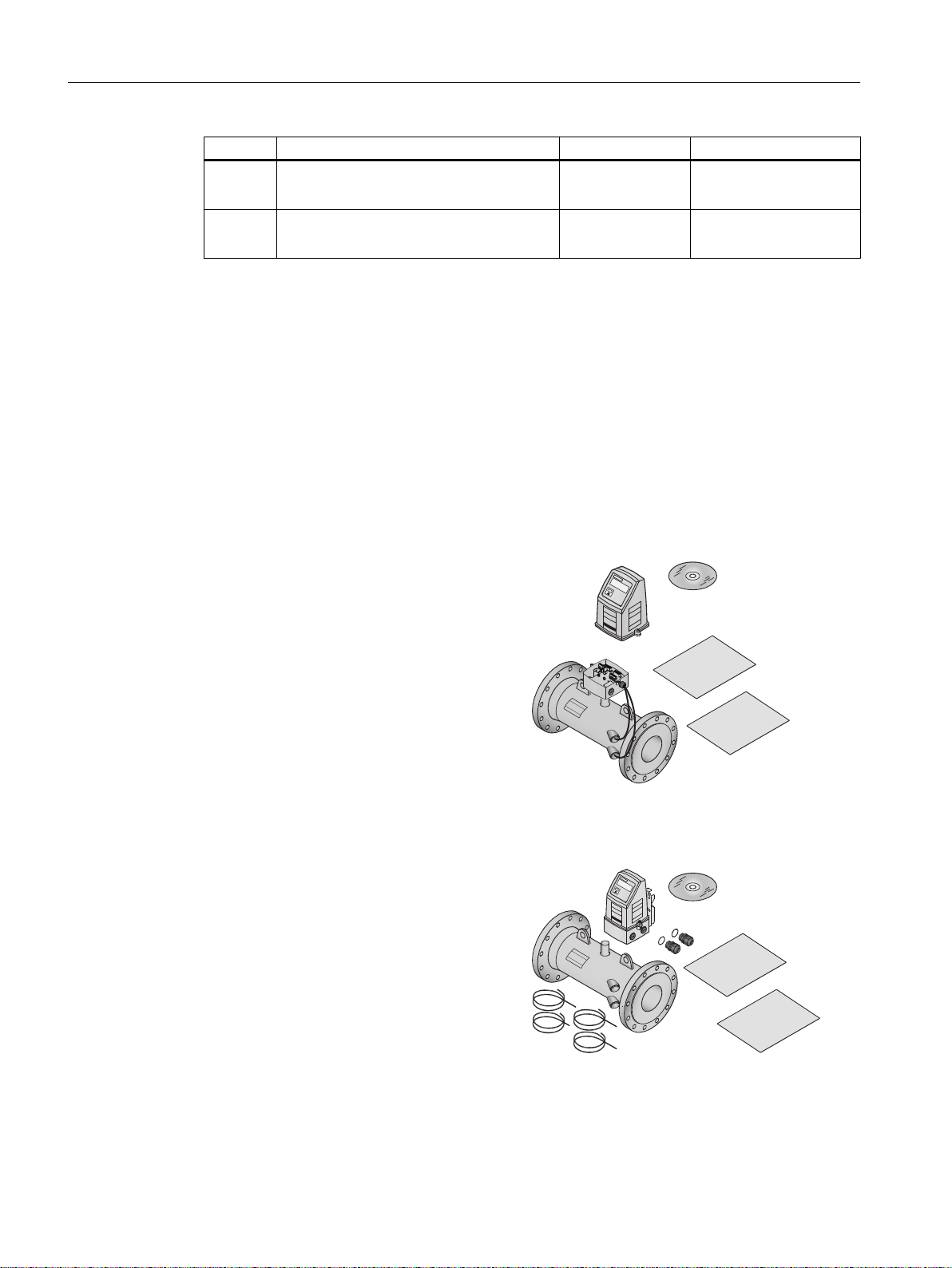
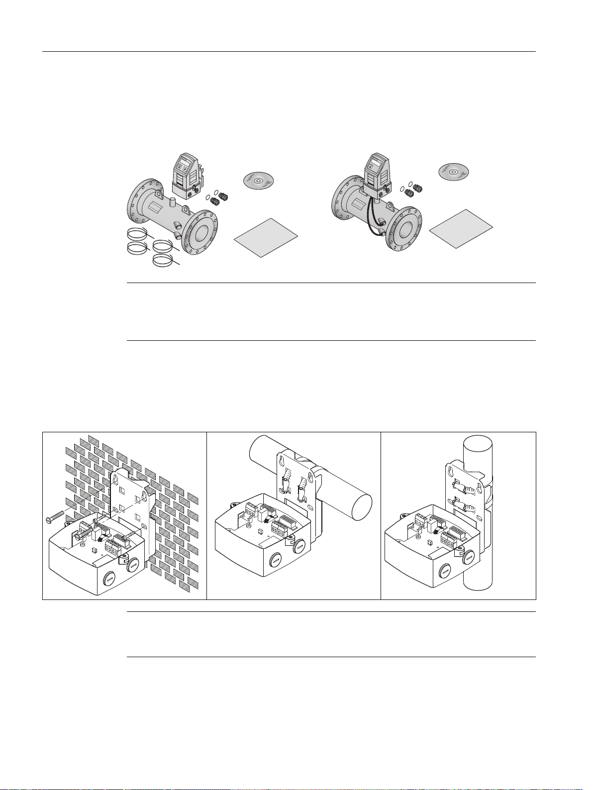
1.3 Items supplied
The device can be delivered as either a compact or a remote system.
Compact system
2.03 1.02.07
2.03 1.02.08-01
● Sensor SITRANS FUS300
● Transmitter SITRANS FUS080 or FUE080
● Siemens Process Instrumentation
documentation disk containing certificates,
and manuals
● Safety note
● Calibration report
Remote system
● Sensor SITRANS FUS300
● Transmitter SITRANS FUS080 or FUE080
● Siemens Process Instrumentation
documentation disk containing certificates,
and manuals
● Safety note
● Calibration report
● Wall/pipe mounting kit with bracket and
terminal box
● 4 Transducer coaxial cables
8 Operating Instructions, 09/2016, A5E00730100-AB
FUS380/FUE380

Note
Scope of delivery may vary, depending on version and add-ons. Make sure the scope of
delivery and the information on the nameplate correspond to your order and the delivery note.
1.4 Checking the consignment
1. Check the packaging and the device for visible damage caused by inappropriate handling
during shipping.
2. Report any claims for damages immediately to the shipping company.
3. Retain damaged parts for clarification.
4. Check the scope of delivery by comparing your order to the shipping documents for
correctness and completeness.
Introduction
1.5 Device identification
1.5 Device identification
The FUS380 or FUE380 flowmeter is delivered with different labels (nameplates) on the
transmitter and sensor. The transmitter and sensor are matched paired.
The transmitter has two nameplates. One (silver) is placed on the front of the transmitter. The
transmitter system nameplate (white) is placed on the right side of the transmitter. Both provide
valuable information about the device and system. The sensor system nameplate (white) is
placed on middle of the sensor.
Note
Identification
Identify your device by comparing your ordering data with the information on the product and
specification nameplates.
FUS380/FUE380
Operating Instructions, 09/2016, A5E00730100-AB 9
1.000000
123412H123
123412H123
FDK:087H2503
2.03
2015
M15
Introduction
1.5 Device identification
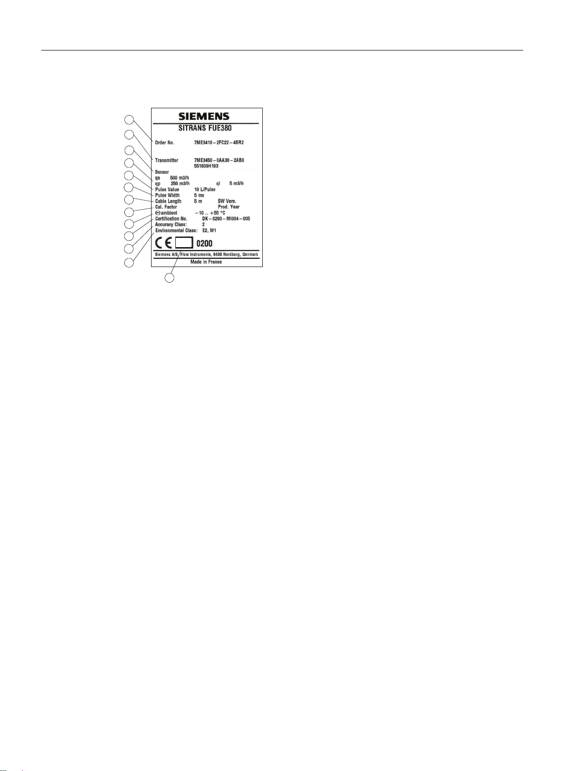
Transmitter system nameplate
① System number (order code identifying selected options and system serial number)
② Transmitter production code and serial number
③ Sensor production code and serial number
④ Maximum flow value (qs), Nominal flow value (qp), Minimum flow value (qi)
⑤ Pulse value (output A)
⑥ Pulse width (output A)
⑦ Cable length (one transducer cable); Software version
⑧ Calibration factor; Production year
⑨ Ambient temperature range
⑩ Type approval number (shown on FUE380 versions only)
⑪ Accuracy class (shown on FUE380 versions only)
⑫ Environmental class (shown on FUE380 versions only)
⑬ Verification markings (shown on MID-verified FUE380 versions only)
Figure 1-1 Transmitter system nameplate, FUE380 example
10 Operating Instructions, 09/2016, A5E00730100-AB
FUS380/FUE380
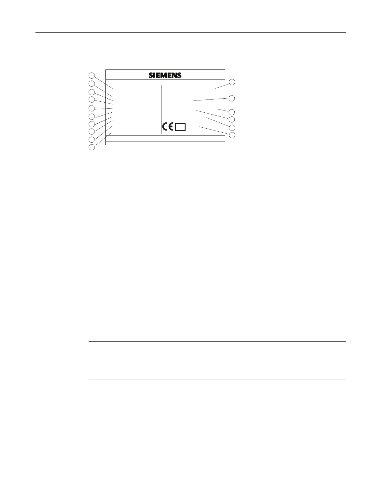
Sensor system nameplate
SITRANS FUE380
Sensor
Dimension
Process Con.
qs
qp / qi
Θmin − Θmax
Cal. Factor
T-amb.
(PS) at +15
°C
(PS) at +200
°C (TS)
Fluid group
FDK-087H2503
123412H123
DN 200
EN 1092-1, PN16
500 m3/h
250 / 5 m3/h
+15 °C ... +200 °C
1.000000
-10 to +55 °C
16 Bar
13.5 Bar
PED/G2
SYSTEM No.
Prod. Year
7ME3410-2FC22-4BR2
123412H123
2015
0200
0200
M15
Siemens A/S, Flow Instruments, 6430 Nordborg, Denmark
Made in France
Accuracy Class: 2
Certification No.: DK-0200-MI004-005
Environmental Class: E2, M1
① Sensor production code and serial number
② Dimension (nominal size ordered)
③ Process connections
④ Maximum flow value (qs)
⑤ Nominal flow value (qp), Minimum flow value (qi)
⑥ Water temperature range
⑦ Calibration factor
⑧ Ambient temperature range
⑨ Maximum allowable working pressures at 15 °C (59 °F) and 200°C (392 °F) (max. tempera‐
⑩ Fluid group
⑪ System number (order code identifying selected options and system serial number)
⑫ Production year
⑬ Certification number (shown on FUE380 versions only)
⑭ Accuracy class (shown on FUE380 versions only)
⑮ Environmental class (shown on FUE380 versions only)
⑯ Verification and PED markings (verification marking shown on MID-verified FUE380 versions
Introduction
1.5 Device identification
ture (TS))
only)
Figure 1-2 Sensor system nameplate, FUE380 example
Note
The matched paired transmitter and sensor shall be mounted together
At installation, please check that the system nameplates of transmitter and sensor have the
same system serial number.
FUS380/FUE380
Operating Instructions, 09/2016, A5E00730100-AB 11

Introduction
1.6 Further Information
1.6 Further Information
Product information on the Internet
The Operating Instructions are available on the documentation disk shipped with the device,
and on the Internet on the Siemens homepage, where further information on the range of
SITRANS F flowmeters may also be found:
Product information on the internet (
Worldwide contact person
If you need more information or have particular problems not covered sufficiently by these
Operating Instructions, get in touch with your contact person. You can find contact information
for your local contact person on the Internet:
Local contact person (http://www.automation.siemens.com/partner)
http://www.siemens.com/flow)
FUS380/FUE380
12 Operating Instructions, 09/2016, A5E00730100-AB

Safety notes
2.1 General safety instructions
CAUTION
Correct, reliable operation of the product requires proper transport, storage, positioning and
assembly as well as careful operation and maintenance.
Only qualified personnel should install or operate this instrument.
Note
Alterations to the product, including opening or improper modifications of the product are not
permitted.
If this requirement is not observed, the CE mark and the manufacturer's warranty will expire.
2.2 Lithium batteries
2
Lithium batteries are primary power sources with high energy content designed to provide the
highest possible degree of safety.
WARNING
Potential hazard
Lithium batteries may present a potential hazard if they are abused electrically or
mechanically. Observe the following precautions when handling and using lithium batteries:
● Do not short-circuit, recharge or connect with false polarity.
● Do not expose to temperatures beyond the specified temperature range.
● Do not incinerate.
● Do not crush, puncture or open cells or disassemble.
● Do not weld or solder to the battery’s body.
● Do not expose contents to water.
2.3 Laws and directives
General requirements
Installation of the equipment must comply with national regulations. For example EN 60079-14
for the European Community.
FUS380/FUE380
Operating Instructions, 09/2016, A5E00730100-AB 13
Safety notes
2.5 Certificates
Instrument safety standards
The device has been tested at the factory, based on the safety requirements. In order to
maintain this condition over the expected life of the device the requirements described in these
Operating Instructions must be observed.
NOTICE
Material compatibility
Siemens Flow Instruments can provide assistance with the selection of wetted sensor parts.
However, the full responsibility for the selection rests with the customer and Siemens Flow
Instruments can take no responsibility for any failure due to material incompatibility.
CE-marked equipment
The CE mark symbolizes the compliance of the device with the following directives:
● EMC-directive 2004/108/EC
● Low voltage directive 2006/95/EC
● Pressure equipment directive (PED/DGRL) 93/23/EC
● ATEX Directive 94/9/EG
2.4 Installation in hazardous area
WARNING
NOT allowed for use in hazardous areas!
Equipment used in hazardous areas must be Ex-approved and marked accordingly!
This device is NOT approved for use in hazardous areas!
WARNING
500 V insulation test
The device is not capable of withstanding the 500 V insulation test required by Clause 6.3.12
of EN60079-11. This must be taken into account when installing the device.
2.5 Certificates
You can find certificates on the Internet at online support portal (http://www.siemens.com/
processinstrumentation/certificates) or on an included DVD.
FUS380/FUE380
14 Operating Instructions, 09/2016, A5E00730100-AB

Description
3.1 Overview
The SITRANS F US ultrasonic flowmeter systems consist of a sensor and a transmitter. This
system consists of sensor type FUS300 or SONOKIT and the transmitters type FUS080 or
FUE080. The transmitter type FUS080 is for the standard flowmeter series SITRANS FUS380
or SONOKIT series. The transmitter type FUE080 is for the type-approved flowmeter series
SITRANS FUE380 with the custody transfer approval for use in energy metering systems. The
transmitters are designed to measure flow in water applications.
The ultrasonic flowmeter transmitter comes as battery or mains-powered version.
The following table shows the ultrasonic flowmeter systems with these transmitter types:
Sensor type Transmitter Flowmeter system
FUS300 (2-path)
DN 50 – DN 1200
FUS300 (2-path)
DN 50 – DN 1200 (with custody transfer approval
for use with heatmeters)
SONOKIT (1- or 2-path)
DN 100 – DN 1200
3
FUS080 FUS380
FUE080 FUE380
FUS080 SONOKIT (1-path / 2-path)
These Operating Instructions are only for the FUS380 and FUE380 flowmeter system. The
FUS080 for SONOKIT and the SONOKIT sensors have separate Operating Instructions.
3.2 System components
The flowmeter system includes:
● Battery or mains-powered transmitter (FUS080 or FUE080)
● Sensor FUS300 as 2-path sensor with flanges and inline transducers wet-calibrated from
factory together with the transmitter (DN 50 (2") to DN 1200 (48"))
or the retrofitting set SONOKIT (1-path for pipe diameters from DN 100 (4") up to DN 1200
(48") or for 2-path from DN 200 (8") up to DN 1200 (48")).
FUS380/FUE380
Operating Instructions, 09/2016, A5E00730100-AB 15
Description
3.4 Features
3.3 Design
The transmitter type SITRANS FUS080 is designed with fiberglass reinforced polyamide
enclosure for remote or compact installation in normal areas. The remote versions are available
with up to 30 meter distance from flowmeter to transmitter. When ordered as a compact version
in the series FUS380 and FUE380 the transducer cables are pre-mounted at the sensor.
The transmitter is available in an IP67/NEMA 4X/6 enclosure and is designed for use in the
flowmeters series:
● SONOKIT (1-path or 2-path)
● FUS380 (2-path)
● FUE380 (2-path)
For spare part cases the transmitter is always ordered as part of a complete flowmeter system,
it can be ordered preprogrammed with the given sensor data (system serial number).
3.4 Features
The following features are available:
● Battery or mains-powered transmitter
● Battery-powered with 3.6 V Lithium dual D-cell batteries
● Suitable for sensor pipe diameters from DN 50 (2") up to DN 1200 (48")
● IP67 (NEMA 4X/6) rated polyamid transmitter enclosure
● Factory preset to the nominal dimensions of pipe type and pipe size
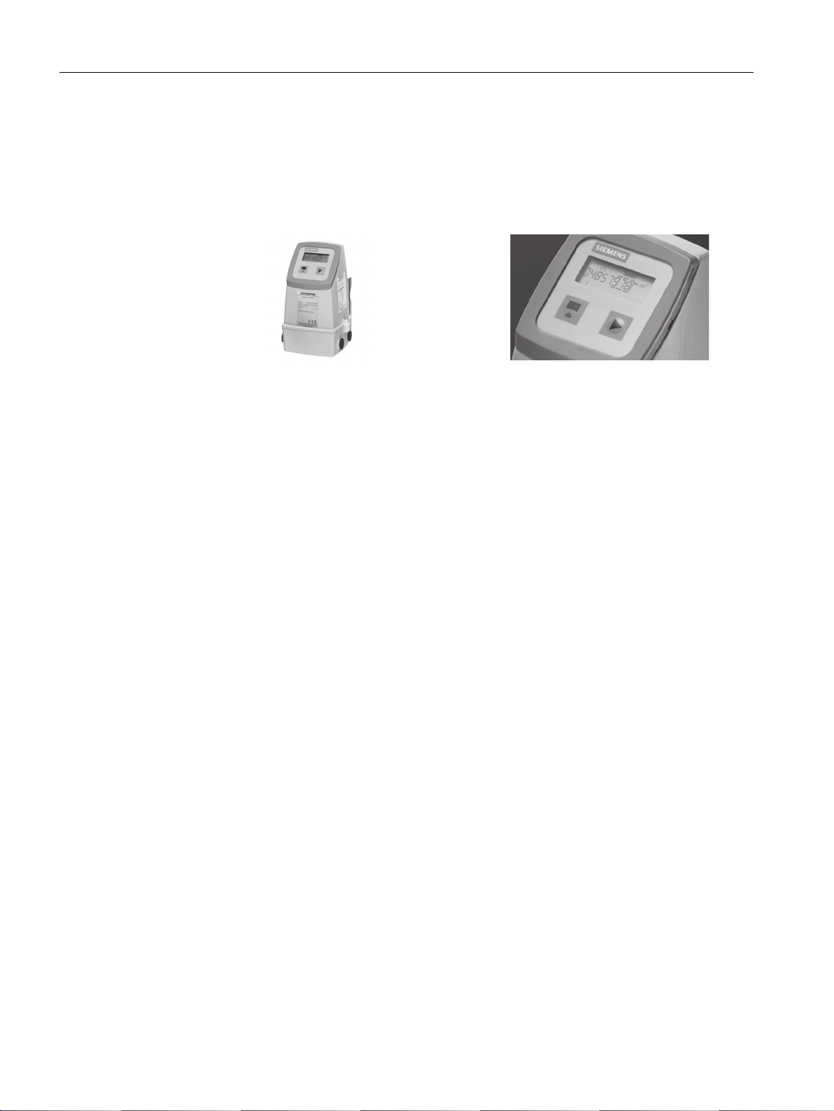
SITRANS FUS080 transmitter
SITRANS FUS080 Display
● Programming via SIMATIC PDM
● Local control panel with single push button, 8-digit display and IrDA optical interface for
communication with SIMATIC PDM
● Display showing accumulated volume as well as instantaneous flow rate. The displayed
units are m3 and m3/h
● Two digital outputs for volume pulse or alarm
FUS380/FUE380
16 Operating Instructions, 09/2016, A5E00730100-AB

Applications
The main application for flowmeters type SITRANS FUS380 / SONOKIT and the typeapproved version FUE380 is measurement of water flow in district heating plants, local
networks, boiler stations, substations, chiller plants, irrigations plants, and other general water
applications.
Integration
The flowmeter pulse output is often used as input for an energy meter or as input for digital
systems for remote reading. The transmitter has two pulse outputs, with functions that can be
individually selected, and integrated IrDA (optical eye) communication interface (Modbus RTU).
The settings of the transmitter, for example flow and pulse output rate, are defined when
ordering the complete flowmeter. If the flowmeter forms part of an energy meter system for
custody transfer, no further approvals are needed, except eventually local approvals on the
flowmeter.
Transmitter communication solutions
The transmitter supports Modbus RTU communication via the optical IrDA interface at the
display, enabling the change of different transmitter settings using the SIMATIC PDM software
tool.
Description
3.4 Features
The FUS080 is configured in a combination of hardware (HW) and firmware (FW). For the
communication and parametrization via SIMATIC PDM a firmware-specific electronic device
description (EDD) is needed. The various relations are listed below:
FW version EDD version
1.02 to 1.05 1.01.04 (with SIMATIC PDM 6 versions)
2.03 1.02.07 (with SIMATIC PDM 6 versions)
2.03 1.02.08-01 (min. SIMATIC PDM 8 versions)
This operating instruction is about the FW 2.03 and related EDD 1.02.08-01 (with min. SIMATIC
PDM 8.2).
FUS380/FUE380
Operating Instructions, 09/2016, A5E00730100-AB 17
Description
3.5 Principle of operation
3.5 Principle of operation
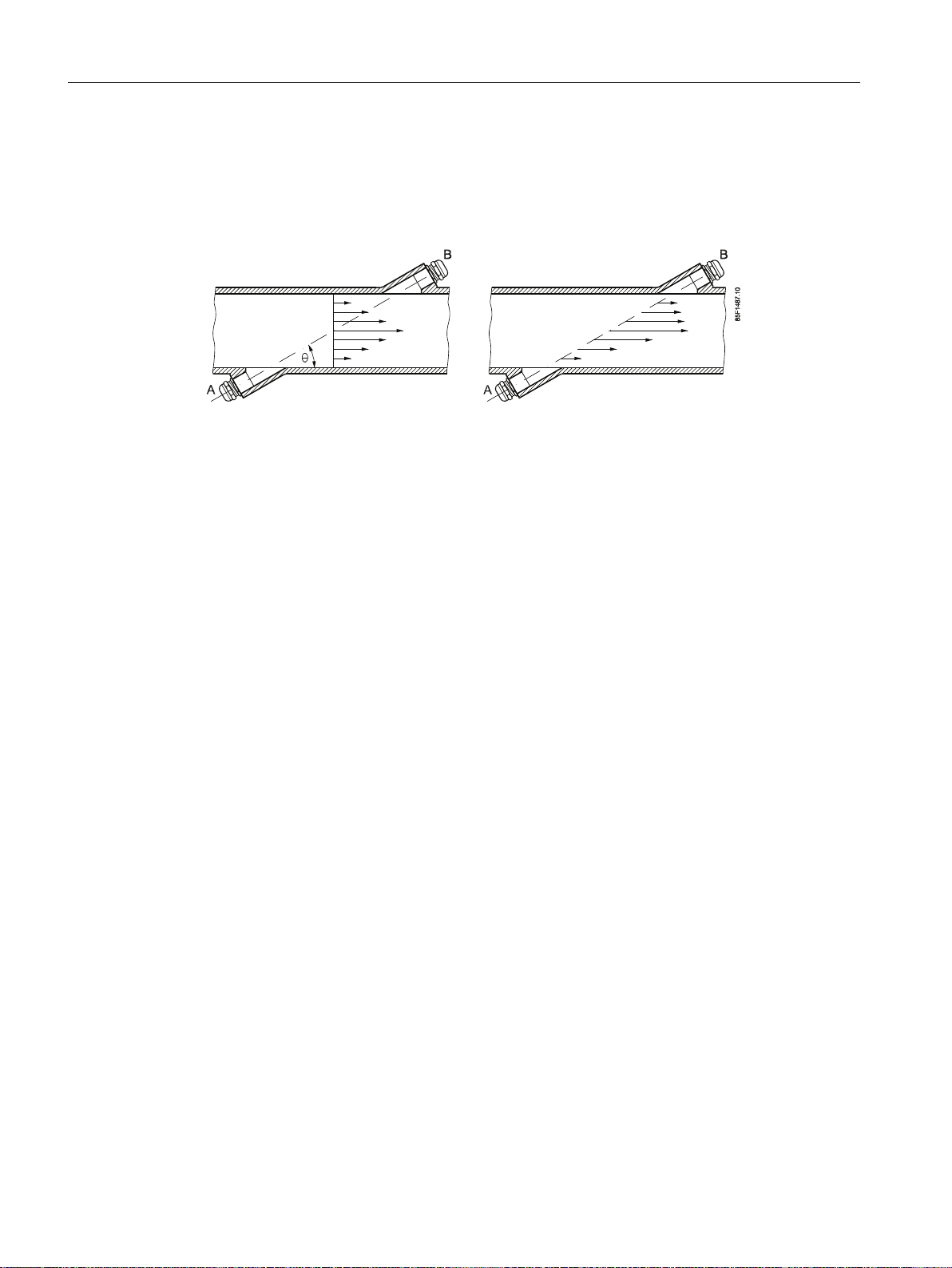
Physical principle
Figure 3-1 Velocity distribution along sound path
A sound wave travelling in the same direction as the liquid flow arrives at point B from point A
in a shorter time than the sound wave travelling against the flow direction (from point B to A).
The difference in sound transit time indicates the flow velocity in the pipe.
Since delay time is measured at short intervals both in and against flow direction, temperature
has no influence on measurement accuracy.
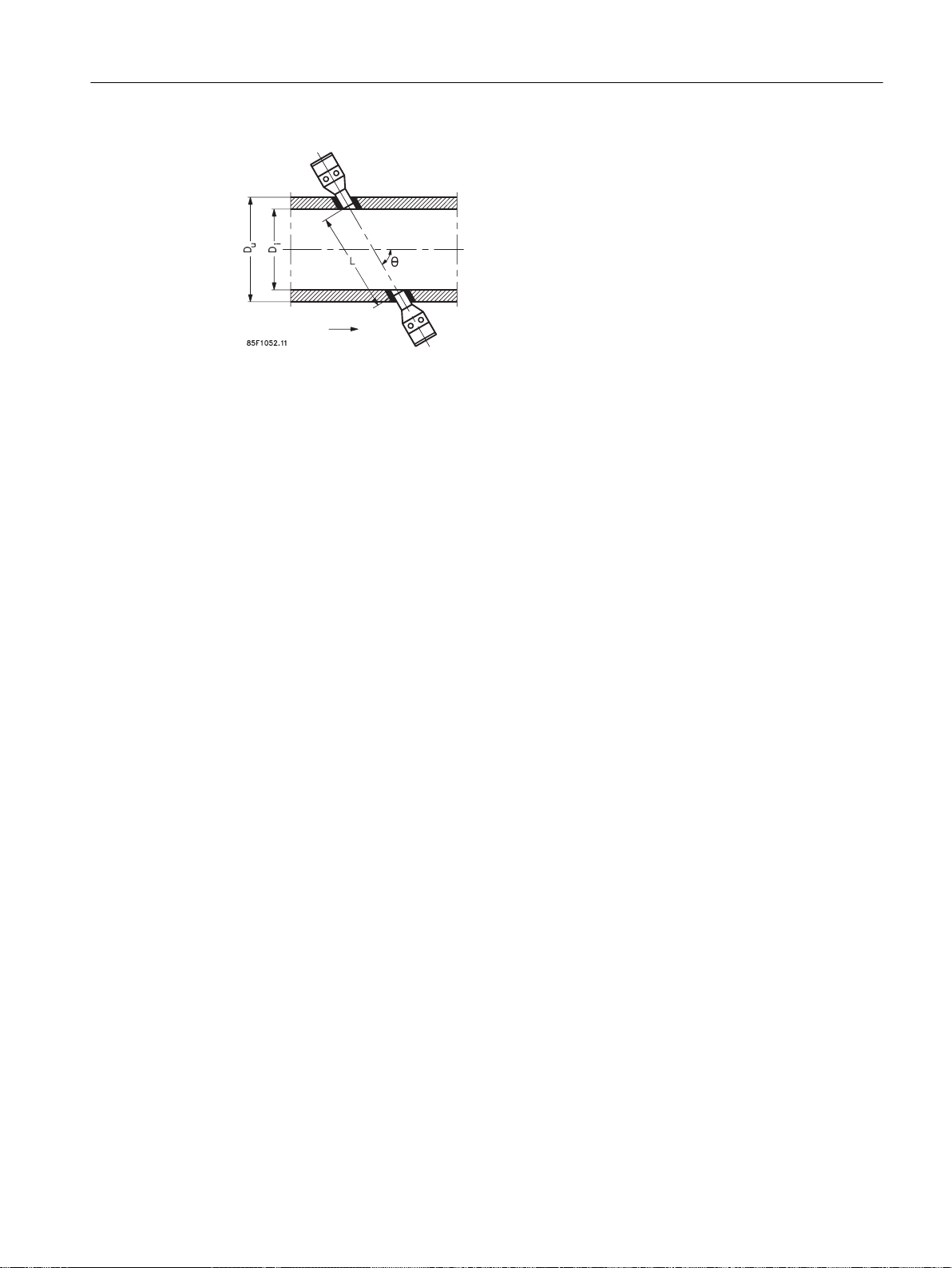
SITRANS F US flowmeters
In SITRANS F US flowmeters the ultrasonic transducers are placed at an angle θ in relation
to the pipe axis. The transducers function as transmitters and receivers of the ultrasonic
signals. Measurement is performed by determining the time the ultrasonic signal takes to travel
with and against the flow. The principle can be expressed as follows:
v = K × (t
where
v = Average flow velocity
t = Transit time
K = Proportional flow factor
This measuring principle offers the advantage that it is independent of variations in the actual
sound velocity of the liquid, i.e. independent of the temperature.
The mechanical/geometrical pipe data is transducer angle (θ), distance between sensors (L)
and pipe dimension (Di and Du) shown in the figure below.
B,A
– t
A,B
) / (t
A,B
× t
B,A
) = K × Δt/t²
FUS380/FUE380
18 Operating Instructions, 09/2016, A5E00730100-AB
1A
1B
Description
3.5 Principle of operation
Figure 3-2 Measuring principle
The ultrasonic signal is sent directly between the transducers. The advantage gained by
sending signals from point to point is an extremely good signal strength.
FUS380/FUE380
Operating Instructions, 09/2016, A5E00730100-AB 19

Description
3.5 Principle of operation
FUS380/FUE380
20 Operating Instructions, 09/2016, A5E00730100-AB

Installing/Mounting
4.1 Flowmeter installation
The flowmeter installation is done in two steps:
1. Sensor installation
2. Transmitter installation
Environment
SITRANS F flowmeters are suitable for indoor and outdoor installations.
● Make sure that temperature and ambient specifications indicated on the device type plate/
label are not exceeded.
CAUTION
Direct sunlight
Device damage.
The device can overheat or materials become brittle due to UV exposure.
Protect the device from direct sunlight.
4
Make sure that the maximum permissible ambient temperature is not exceeded.
Refer to the technical data in FUS380 and FUE380 systems (Page 79).
Ambient temperatures for FUS080:
● MID version: -10 to +55 °C (14 to 131 °F)
● Non-MID version: -10 to +60 °C (14 to 140 °F)
See also Insulation (Page 26).
The enclosure rating of the transmitter is IP67 (NEMA 4X/6) or better.
4.2 Sensor installation
4.2.1 Inlet/outlet conditions
Requirement for straight inlet before flowmeter
In order to maximize performance it is necessary to have straight inlet and outlet flow conditions
before and after the flowmeter.
Furthermore, a minimum distance between flowmeter and pumps and valves must be
respected.
FUS380/FUE380
Operating Instructions, 09/2016, A5E00730100-AB 21
Installing/Mounting
4.2 Sensor installation
It is also important to centre the flowmeter in relation to flanges and gaskets.
Make sure that the flowmeter is positioned as low as possible to prevent air from being trapped
in the flowmeter at the transducers.
Find a position on the pipeline where the inlet pipe tothe flowmeter has a straight length as
specified below.
Note
MID-approved FUE380 systems
Minimum straight inlet pipe: 1.5 m. See further recommendations below.
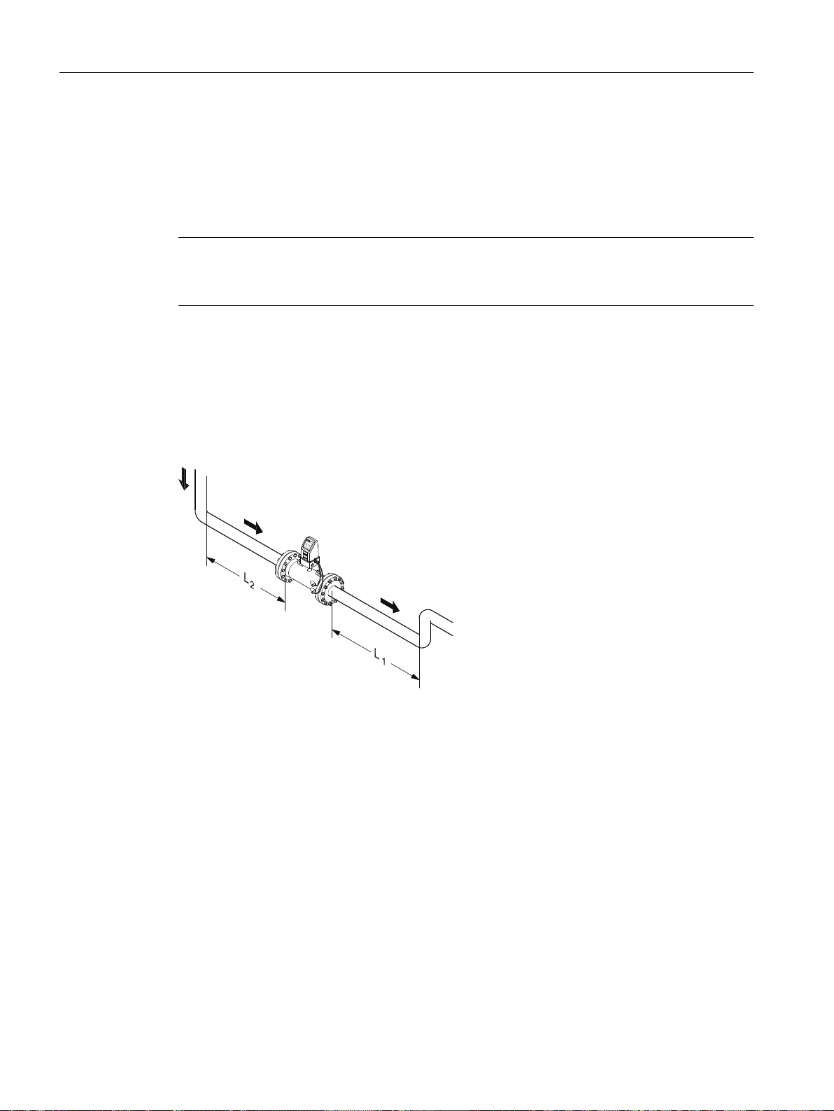
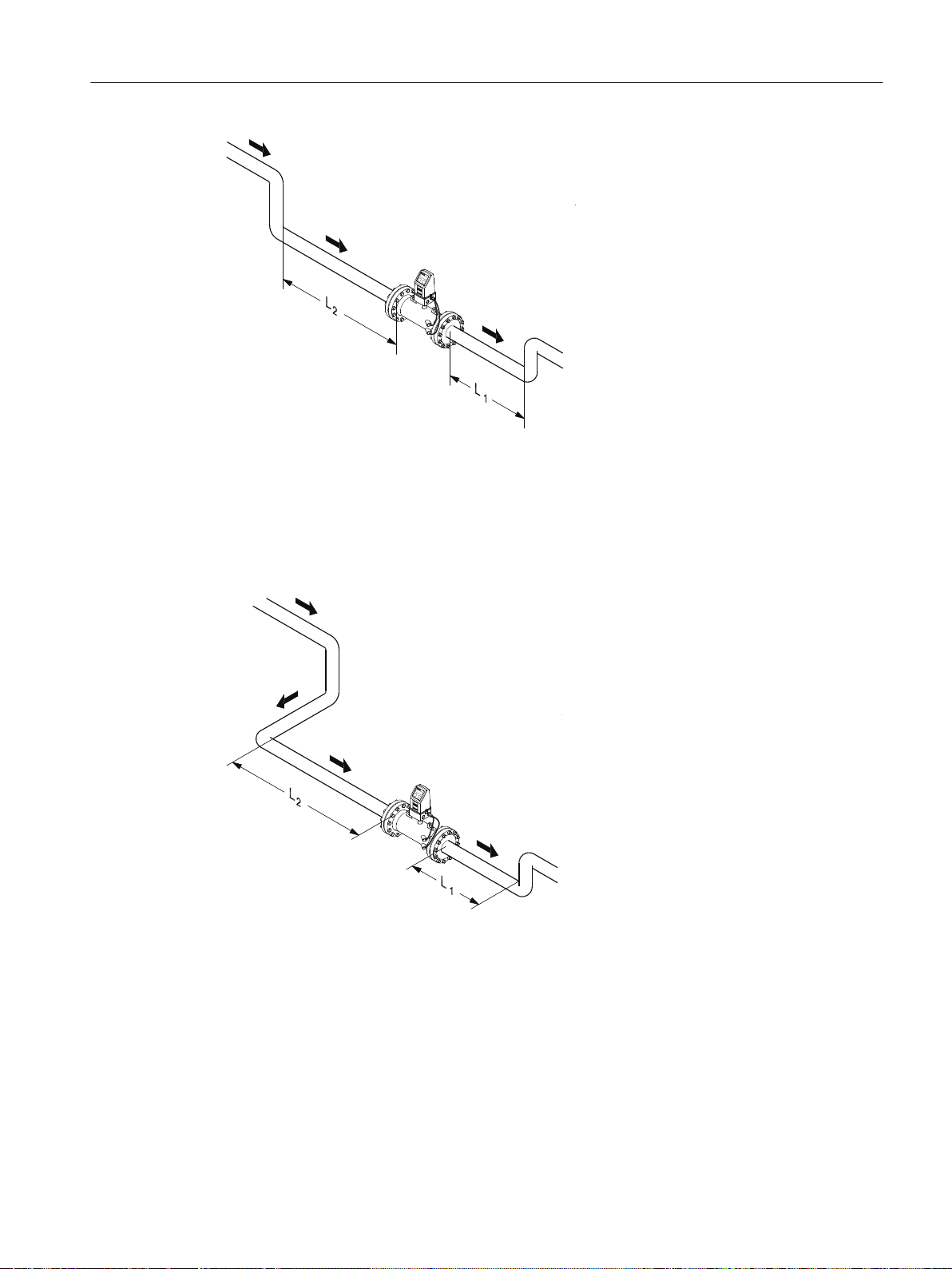
Single bend
1 x 90° bend
L2: Min. 10 x pipe diameter
L1: 3 x pipe diameter
Dual bend
2 x 90° bends in the same plane
L2: Min. 10 x pipe diameter
L1: 3 x pipe diameter
FUS380/FUE380
22 Operating Instructions, 09/2016, A5E00730100-AB
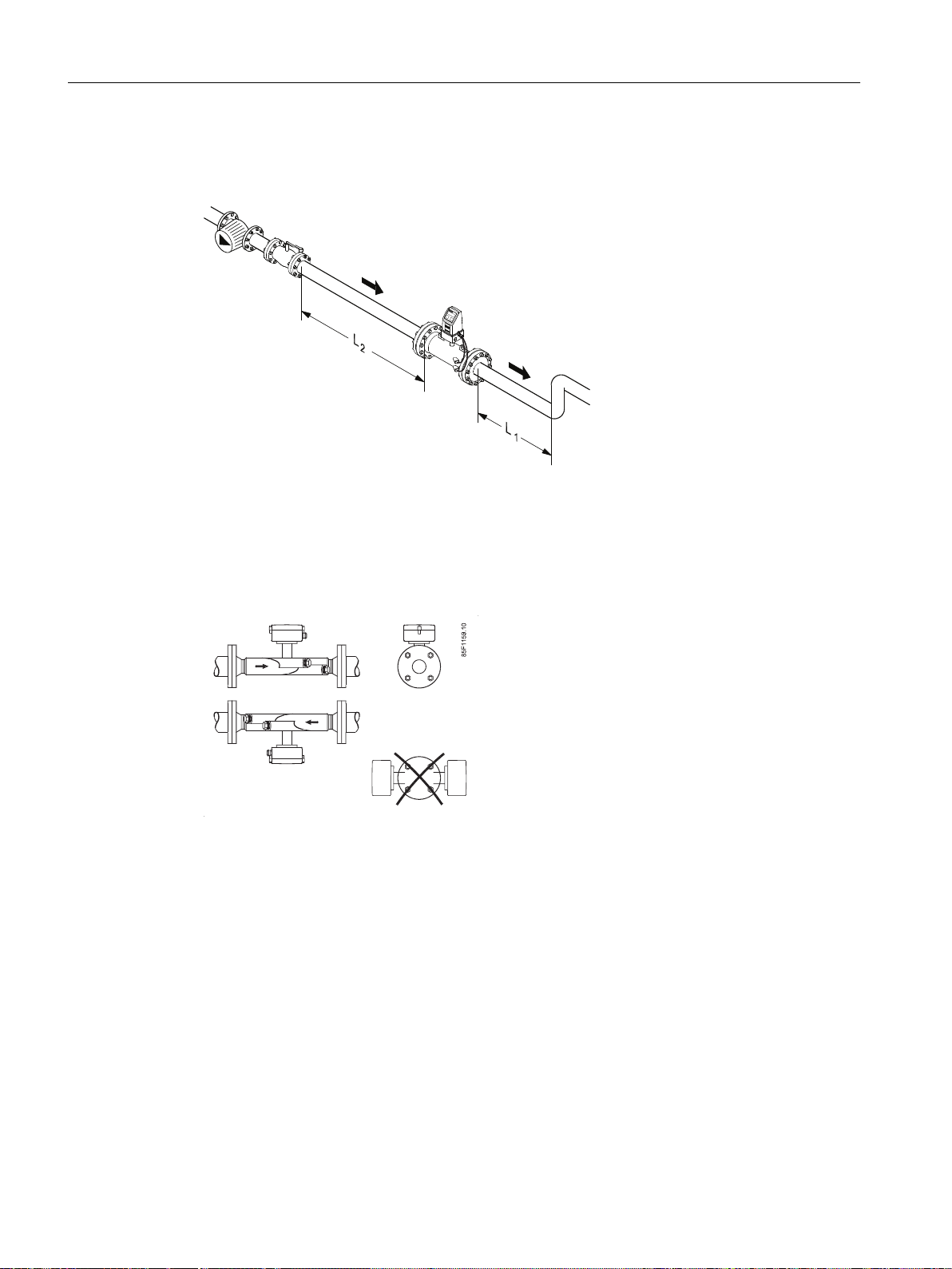
Triple bend
Installing/Mounting
4.2 Sensor installation
3 x 90° bends in two planes
Valves and pumps
L2: Min. 20 x pipe diameter
L1: 3 x pipe diameter
Valves
L2: Min. 10 x pipe diameter, fully open valve
L1: 3 x pipe diameter
Partially opened valves
L2: Min. 40 x pipe diameter, partially opened valves (or equal valves design)
Pumps
FUS380/FUE380
Operating Instructions, 09/2016, A5E00730100-AB 23
Installing/Mounting
4.2 Sensor installation
L2: Min. 20 x pipe diameter
L1: 3 x pipe diameter
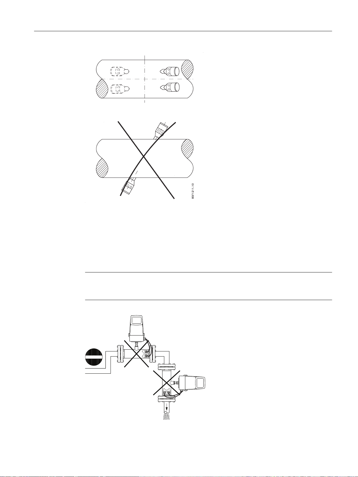
Orienting the sensor
Horizontal orientation: sensors with terminal box must be mounted with the terminal box in
upwards or downwards position. Sensor without terminal box (remote versions) must be
mounted with the transducers in the vertical plane.
In horizontal installation avoid any upward/downward position of the transducers.
FUS380/FUE380
24 Operating Instructions, 09/2016, A5E00730100-AB
Installing/Mounting
4.2 Sensor installation
Precautions
Avoid installation at the highest point in the system because air bubbles will be trapped in the
flowmeter.
Avoid installation at a point where there is a free outlet after the flowmeter.
The flowmeter pipe section may be installed in either a horizontal or vertical position.
Note
To obtain maximum battery lifetime of the Lithium Thionyl Chloride battery pack, Siemens
recommends installing the flowmeter transmitter in an upright position.
FUS380/FUE380
Operating Instructions, 09/2016, A5E00730100-AB 25
Installing/Mounting
4.2 Sensor installation
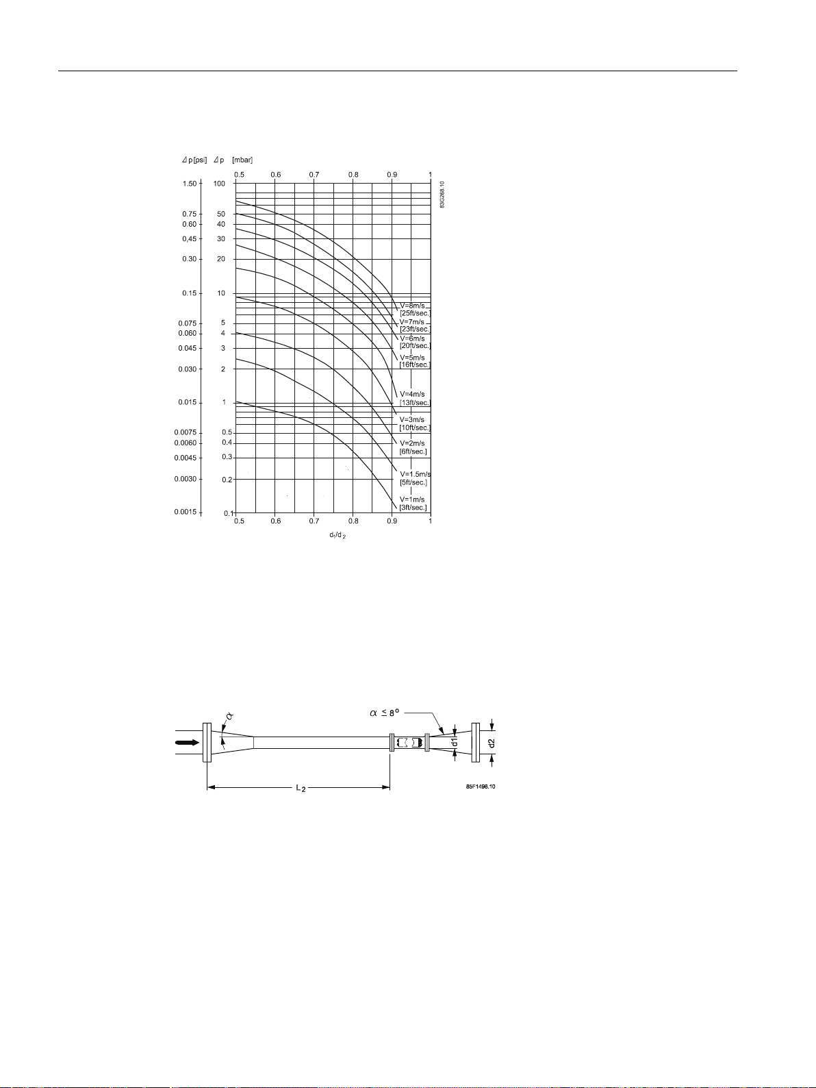
4.2.2 Reduction
Installation in large pipes
The flowmeter can be installed between two reducers as shown. At 8° reducing angles the
below pressure drop curve applies.
Delta-P example:
A water flow velocity of 3 m/s (V) in a sensor with a diameter reduction from DN 200 to DN
100 (D1/D2 = 0.5) gives a pressure drop of 9 mbar.
L2: Min. 10 x pipe diameter
4.2.3 Insulation
Siemens always recommends insulation of the sensor in both the compact and the remote
versions. This recommendation applies to both battery-powered and mains-powered versions.
The insulation will prevent heat transfer to the transmitter (compact versions) or terminal box
(remote versions).
FUS380/FUE380
26 Operating Instructions, 09/2016, A5E00730100-AB
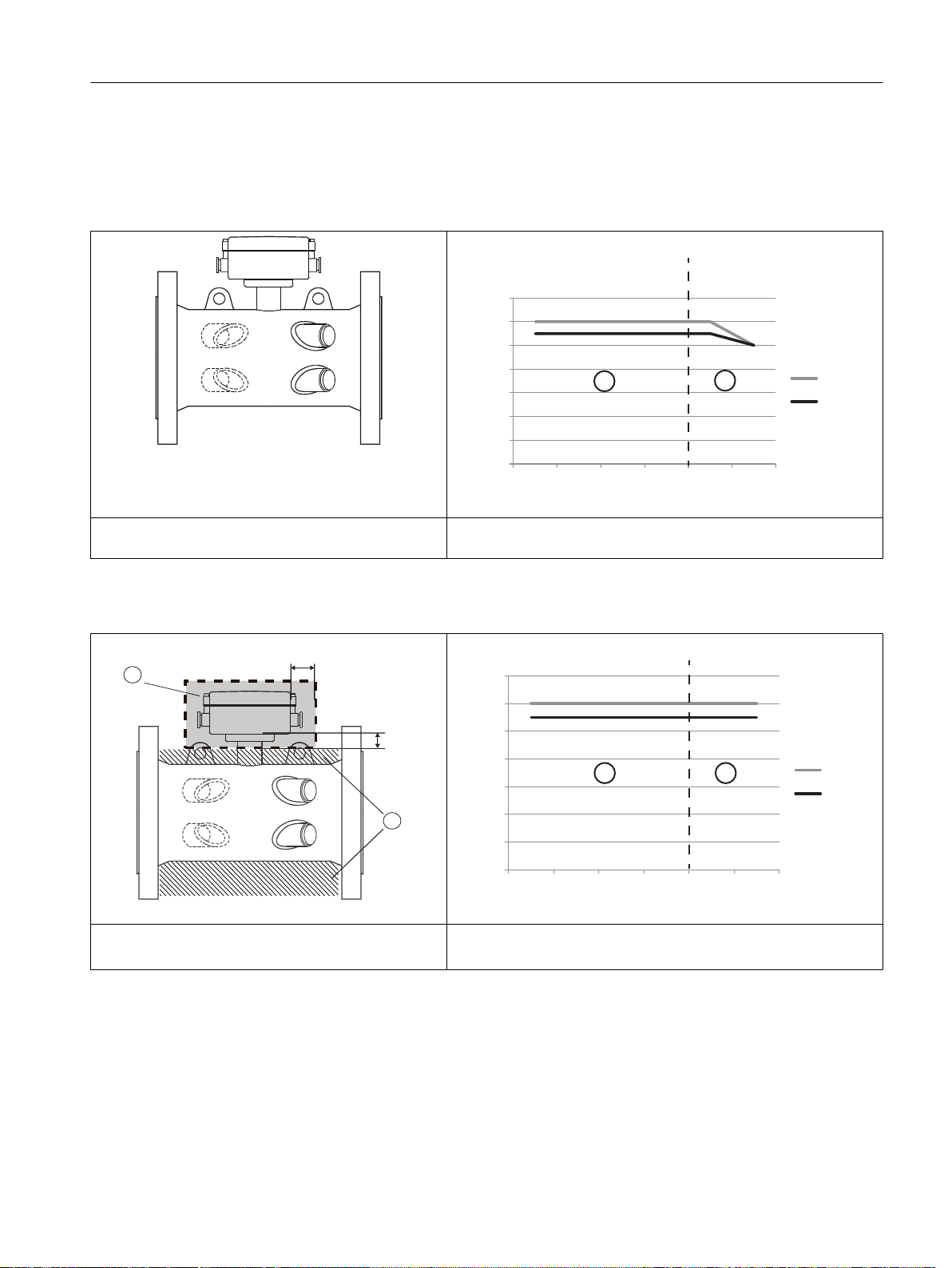
For media temperatures above 120 °C (248 °F) only remote installation is allowed.
0
10
20
30
40
50
60
70
10- 10 50 100 140 200
FUS 380
FUE 380
0HGLDWHPSHUDWXUHr&
$PELHQWWHPSHUDWXUHr&
0LQPP
0LQPP
2
0HGLDWHPSHUDWXUHr&
$PELHQWWHPSHUDWXUHr&
0
10
20
30
40
50
60
70
10- 10 50 100 140 200
FUS 380
FUE 380
Temperatur specifications for non-insulated sensors
① Compact and remote versions
Installing/Mounting
4.3 Transmitter installation (compact/remote versions)
② Remote versions only
Temperatur specifications for insulated sensors
① Keep terminal box free from insulation (gray area)
4.3 Transmitter installation (compact/remote versions)
FUS380/FUE380
Operating Instructions, 09/2016, A5E00730100-AB 27
① Compact and remote versions
② Insulation
The transmitter is packed separately - ready for plug-in into base part.
② Remote versions only
Safety N
ote
mnnmnmn
nmmnnmmnmnnmnmn
nmmn
nmmnmnnmnmn
mnmnnmnmn
mnn
m
nm
nn
mnn
m
nm
n
mnn
m
nm
nn
m
nmnn
mnnm
n
n
nnmnmn
mnnmnmn
nmmnnmmnmnnmnmn
nmmn
nmmnmnnmnmn
mnmnnmnmn
mnn
m
nm
nn
mnn
m
nm
n
mnn
m
nm
nn
m
nmnn
mnnm
nn
nnmnmn
Safety N
ote
Installing/Mounting
4.3 Transmitter installation (compact/remote versions)
There are two mounting versions of the transmitter (as shown in figures below):
● remote transmitter
● compact transmitter
Note
The matched paired transmitter and sensor shall be mounted together. At installation, please
check that the system nameplates of transmitter and sensor have the same system serial
number.
4.3.1 Installation wall mounting kit (remote transmitter)
Mount wall/pipe mounting bracket in an appropriate place.
Note
Take the connection cable length into consideration, and allow adequate space for the cable
inlets.
28 Operating Instructions, 09/2016, A5E00730100-AB
FUS380/FUE380

4.3.2 Battery-powered transmitter
The battery-powered transmitter is prepared for one battery pack of 2 lithium 3.6 V D-cell
batteries and a single backup battery. The battery lifetime depends on the use of the different
functions, for example the use of Modbus IrDA communication or higher pulse output frequency
will decrease the lifetime significantly. Under normal temperature and working conditions a
battery can have an operation lifetime of up to 6 years. The typical liftetime of a dual battery
pack with nominal working pulse output frequency of 20 Hz is approximately 4.2 years.
Siemens recommends replacing batteries after maximum 6 years. For the replacement, see
Battery replacement (Page 63) and Start-up routine (Page 47). Every time a battery plug is
reconnected, the unit runs a start-up routine, see Start-up routine (Page 47).
Note
The male battery plug is not connected upon delivery. This connection must be made to enable
the back-up battery power supply.
Note
Changing the battery does not influence the settings and accumulated values.
Installing/Mounting
4.3 Transmitter installation (compact/remote versions)
FUS380/FUE380
Operating Instructions, 09/2016, A5E00730100-AB 29

Installing/Mounting
4.3 Transmitter installation (compact/remote versions)
FUS380/FUE380
30 Operating Instructions, 09/2016, A5E00730100-AB
 Loading...