

Siemens SITRANS F FUH1010, SITRANS F FUH1010BX, SITRANS F FUH1010GX, SITRANS F FUH1010DVX, SITRANS F FUH1010X Operating Instructions Manual
...
SITRANS F
SITRANS FUH1010 NEMA 7 Compact
Interface Detector 7ME3601-1, 7ME3601-2
Operating Instructions
Siemens Hardware
6/2014Edition
Answers for industry.

Errata
1010FMA-45
ERRATA
Power Supply Wiring Procedure Update
NOTE: The following applies to System 1010X, 1010BX, 1010DVX, 1010PVX, 1010GX,
1010GCX, 1010GCSX and 1010SPVX Flowmeter installation manuals.
Replace the “Power Connections” description and set up procedure with the following. Note that
paragraph numbers are different for all the above mentioned manuals. The example below is for
the 1010X manual.
NOTE: For flowmeters refer to d
rawings 1010X-7 (1 of 3) & 1010DX-7 (1 of 3) and
for Interface Detectors refer to drawings 1010BX-7 (1 of 3) & 1010BDX-7
(1 of 3).
2.2 POWER CONNECTIONS
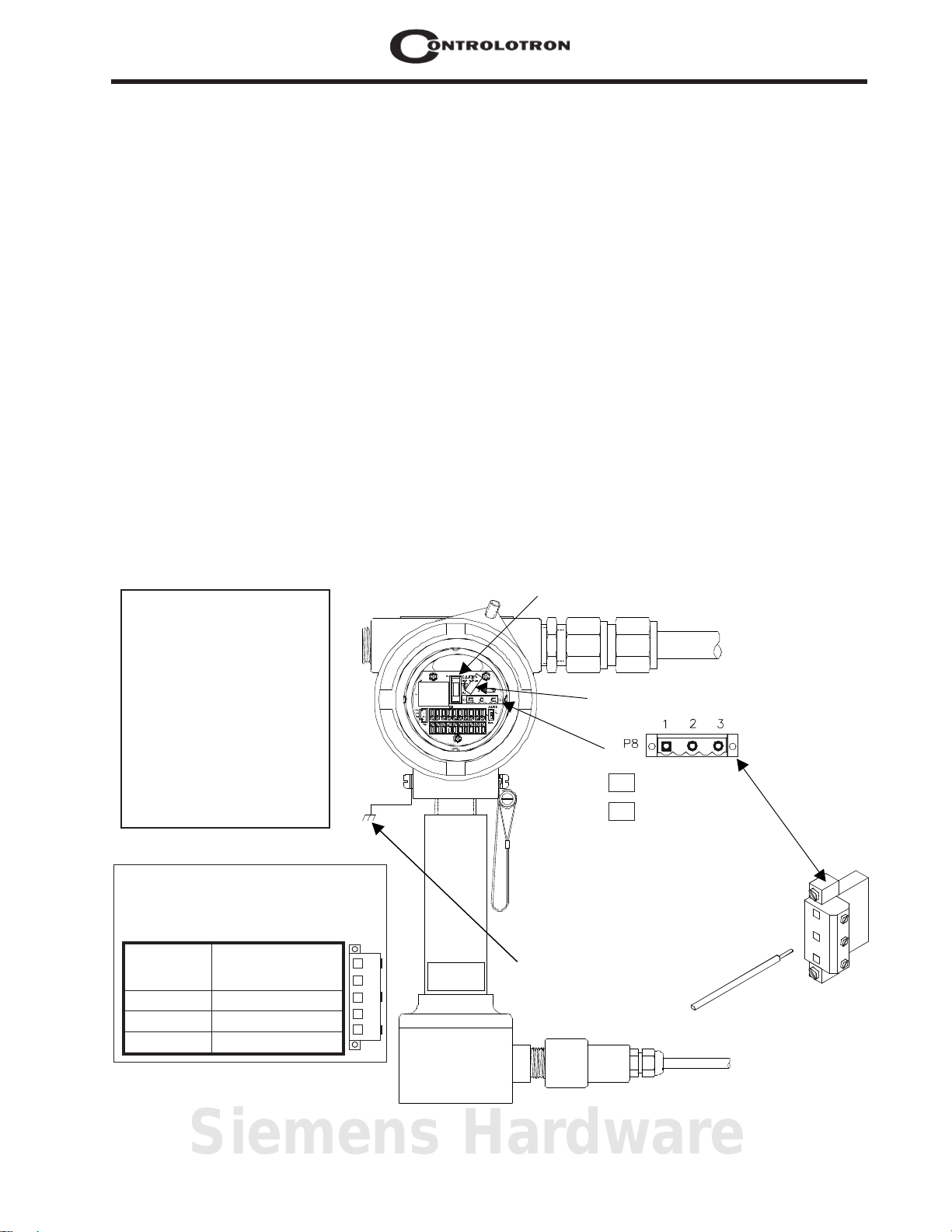
2.2.1 INPUT POWER CONNECTOR (P8) AND FUSE (F1) LOCATIONS
The standard 1010X flow computer either requires 100/120/200 VAC or one of three 9-36 VDC
power sources for its power input. The power input is protected by a GMA 2A fuse (F1). Please
replace this fuse with the exact type if it becomes necessary to do so.
WARNING
Do not connect AC or
DC power to flowmeter
until the correct type of
input power is determined. See P/N
tables on next page.
Contact with exposed
wiring may lead to fire,
electric shock, or serious personal injury.
Fuse (F1) GMA 2A
Cable
Clamp
AC HOT NEU GND
DC + - GND
WARNING
Connect power per instructions below.
See field manual for complete power
supply wiring procedures.
Terminal
Number
1
2
3
Sample Power Label Located Inside Rear
Housing Cover.
1010X-6SS2
90-230 VAC
(Single Phase)
Hot
Neutral
Ground
1
2
3
This must be
connected to
Earth Ground.
Siemens Hardware
E-1
1010FMA-45Errata
GND
GND
3
2
1
HOT
+
DC
AC
P8
NEU
-
2
3
1
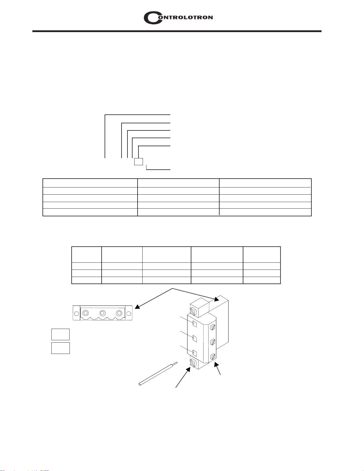
Connector
Mounting
Screws
Stripped Wire
Wire
Clamp
Screws
2.2.2 POWER SUPPLY WIRING
l Using a 1/16" Hex key, loosen the 1010X Rear Housing Cover locking setscrew.
l Unscrew the Rear Housing Cover and remove.
IMPORTANT: Power Supply label is located inside the Rear Housing cover.
l Locate power supply connector J8. Use the tables below and the part number of your unit to
determine the correct input power source. (See also metal ID label on unit housing.)
*Typical 1010X Part Number Construction:
Root Meter Number
Transducer Support
Relay Support
Numeric Display
Power Supply Option
1010X-T2KNZPL2-S2----Safety Rating Option
Language Option
Meter Part Number * Power Supply P/N User Supplied Power
Contains S prior to S_Code 1010X-6SS2 90-230 VAC Single Phase
Contains a ZN prior to S_Code 1010X-6ZNS2 9-36 VDC Negative Ground
Contains a ZP prior to S_Code 1010X-6ZPS2 9-36 VDC Positive Ground
Contains a Z at end of P/N 1010X-6Z 9-36 VDC Floating
l Pull wires through flowmeter case conduit cable hole.
l Wire input power connector P8 for AC or DC power as shown below. Insert wires into wire
entry holes and secure by tightening wire clamp screws (see note on next page).
Terminal 1010X-6SS2 1010X-6ZNS2 1010X-6ZPS2 1010X-6Z
Number
1 Hot Positive Positive (Gnd) Positive
2 Neutral Negative (Gnd) Negative Negative
3 Ground Ground Ground Ground
NOTE: Loosen Wire
Clamp Screw, insert
stripped end of wire
and then retighten.
NOTE: Power Supply connector wires should be stripped stranded or solid conductors
AWG 12 -18.
Input Power Connector (P8) Wiring
E-2

Errata
Menu Lockout
Switch (S1)
NOTE: The input power connector consists of a removable wire plug and PCB header located on
the 1010X-8 I/O module. Two screws secure the wire plug to the header. The connector assembly
is fully polarized for fast and easy mating. The wire plug accepts stranded or solid conductors of
AWG 12 - 18. To insert a wire into the wire plug, strip back the insulation by 0.31" (8 mm), loosen
the wire clamp screw, insert the stripped wire end and then re-tighten the wire clamp screw.
l Plug input power connector P8 into connector J8 and secure using two captive connector
mounting screws as indicated above.
l Secure power-input cable with cable clamp to prevent wire breakage.
l Replace Rear Housing Cover and tighten setscrew.
l Connect the power cables to the appropriate power source previously selected from the tables
above and power up unit.
l If unit is operational, turn power off and install transducer cables.
1010FMA-45
2.3 THE MENU LOCKOUT SWITCH
System 1010X includes a menu lockout switch to prevent unauthorized access to the Installation
Menu. In addition, a password entry option is available (see Channel Setup). The menu lockout
switch (S1) resides on the I/O module on the right side of I/O wiring terminal block TB1 (see
below). Please switch to the unlocked position before attempting to program the flowmeter. We
recommend that the installation menu remains locked during normal operation. (Refer to appropriate manual section for TB1 and TB2 signal wiring.)
Siemens Hardware
E-3


Errata
1010FMA-61
ERRATA
FUH1010 Interface Detector Compact NEMA 7 Manual Updates
1. FUH1010 Interface Detector NEMA 7 Compact Flow Meter Manual
Troubleshooting Table Update
In the FUH1010 Interface Detector NEMA 7 Compact flow meter manual P/N CQO:1010BXFM-3 Revison
B replace the troubleshooting table in Section 2 - Installation Menu on pages 2-58, 2-59 and 2-60 with
the following:
Error or Message Probable Cause Solution
Memory Full!
Memory Corrupted!
Chan Not Setup
Clr Active Memory?
Clr Save Data?
<EOT> Response to a request to output
No Sites - Press <ENTER>
Security
RTC Error Component level problem.
Response to an attempt to save site
data when data memory is full.
Memory read error occurred while
accessing the active site data.
Response to an attempt to invoke
an operation that requires a channel to be enabled.
Use this function to restore operation if a severe event (e.g. a violent
power surge) disrupts system
operation.
[Clr Saved Data?] only appears
after pressing <Down Arrow> in
response to [Clr Active Memory?].
Datalogger data to the printer or
the Graphics screen when no
datalogger data exists or at the end
of a transmitted file.
Response while trying to recall/
delete a site setup when no sites
are stored.
Response upon charging previously
entered data when security switch
is in [Disable] position or security
code has been entered.
Delete an obsolete site or clear
Datalogger memory to make
room for the new data.
Refer to F4 reset procedure in
the Operation Instructions
manual.
Enable the channel [Channel
Setup Channel - Enable - Yes].
Note that a channel cannot be
enabled until an “Install” operation is completed.
Refer to F4 reset procedure in
the Operation Instructions
manual.
Answering [Yes] to [Clr Saved
Data?] will erase ALL saved
data. To invoke in RS-232 serial
mode, type @@@ and then
press <ENTER> key.
Set up the Datalogger.
Create a site.
Change switch position to
[Enable].
Enter previously set security
code.
Meter requires service. Request
RMA.
(continued)
Siemens Hardware
E-1

Error or Message Probable Cause Solution
- - -F - - -Fault Alarm
• Loss of signal signal strength
• Recouple sensors with fresh
couplant.
• Change of Rx signal location (Beam
Blowing)
• Install Sensors in Direct mount
mode.
• Note: If problem persists call
Tech support.
1010FMA-61Errata
Re-space Index
Invalid Setup (use Direct Mode)
The measured liquid sonic velocity
(Vs) is more than +/- 25 % of the average Vs range.
During the Initial Makeup, the system
detects invalid sensor spacing, erroneous liquid/pipe parameters, or
some other factor that prevents it
from completing the Initial Makeup.
• Ensure proper pipe dimensions
and/or Liquid data entries are correct.
• Properly enter correct Sensor
Size into meter [Install Sensor]
menu.
• Confirm sensor spacing is cor-
rect by checking [Install Sensor]
menu spacing parameters.
This may be due to one of the following:
• An out-of-range data entry.
• An invalid condition; (e.g.,
overlapping sensors in Reflect
Mode). If selecting Direct Mode
does not resolve, review all site
setup and sensor installation
choices; particularly data entered for the pipe and liquid.
• In Reflect Mode, the flow
meter detects that the pipe wall
signal may impinge upon the
liquid signal. Use Direct Mode
instead.
E-2
Trigger <ENTER>, <UP Arrow>,
<DOWN Arrow>, or <LEFT Arrow> to abort install routine. Continue programming other site data
in anticipation of resolving the difficulty later. Call technical support
for help if necessary.
(continued)

Errata
Error or Message Probable Cause Solution
Low Signal - Press <ENTER>
During the Initial Makeup the flow
meter decides that a level of the receive signal is insufficient for proper
operation.
Some reasons for low signal are:
• Invoking [Install Complete?] on
an empty pipe.
• Coupling compound insufficient,
not applied or evaporated. Reapply couplant.
• A disconnected or broken sen-
sor cable.
• The pipe needs to be condi-
tioned at the mounting location.
• Flush out large air bubbles.
• The sensor cables are defec-
tive or not connected to the correct channel.
1010FMA-61
Detection Fault
If it appears that the flow meter can
not complete an Initial Makeup this
means that the pipe and/or liquid conditions do not permit a recieve signal
that meets the flow detection standards.
The system will not operate.
• The Set Empty routine per-
formed when pipe was NOT actually empty.
• If you locate and correct the im-
proper condition immediately trigger <ENTER> to resume the installation procedure. Otherwise,
trigger the <Left Arrow> to abort
the installation and conduct a thorough investigation.
Attempt to improve operating conditions by reinstalling the sensors
at a different spacing offset, or
even at a different location on the
pipe.
Switching from Reflect to Direct
Mount may solve the problem.
However, operation may not be
possible if there is poor liquid, pipe
wall sonic conductivity or extreme
liquid aeration.
Siemens Hardware
E-3

1010FMA-61Errata
2. DIN Pipe Table Note
In Section 2, add the following note right after paragraph 2.2.1 How to Select a Pipe Class:
NOTE:
The DN sizes listed in the [Select Pipe Size] menu option list are referenced to DIN Table
2448. After selecting pipe size, check pipe OD and wall thickness for correct dimensions.
3. Empty Pipe Set Procedure Update
In Section 2, paragraph 2.4.10 Empty Pipe Set Menu replace the introductory paragraphs and
warning with the following:
The flow meter performs the MTYmatic routine automatically during its Initial Make-up to establish a standard setting for the Empty Pipe alarm. This process is normally sufficient for setting
this parameter. The [Empty Pipe Set] option list allows you to re-invoke MTYmatic, use an
Actual MTY routine (if application conditions allow you to empty and refill the pipe) or use the
Set Empty routine to set the empty pipe threshold by direct numeric entry.
How To Use the Actual MTY Command
If application conditions allow you to empty and refill the pipe, then you may choose to perform
the Actual Empty procedure; however, it is not required to do so.
WARNING: NEVER perform the Actual MTY procedure if the pipe can not be emptied.
E-4

IMPORTANT NOTICE
Controlotron is now part of:
Siemens Industry, Inc.
Industry Automation division
CoC Ultrasonic Flow
Hauppauge, NY 11788 USA
SITRANS FUH1010BX
INTERFACE DETECTOR
This equipment contains components that are
susceptible to electrostatic discharge (ESD).
Please observe ESD control measures during
the handling and connection process.
Field Manual CQO:1010BXFM-3 Rev C
June 2014
For use with Operating System
Software Version 3.01.5B or later
Copyright©2014 Siemens Industry, Inc. All Rights Reserved Made in the USA
Siemens Hardware

Manual Changes
NOTE: For the latest updates and revisions to this field manual go to:
http://support.automation.siemens.com/ and check the Product Manual listing.

MANUAL
ADDENDUM
1010FMA-58
Digital Damping
Procedure Update
For Gas & Liquid
Flowmeters
Manual Addendum
September 2008
Copyright © 2008 Siemens Industry, Inc. All rights reserved Made in the USA
Siemens Hardware


Manual Addendum
1010FMA-58
Digital Damping Procedure Update for Gas & Liquid Flowmeters
INTRODUCTION
The following Digital Damping procedure updates are for SITRANS F gas and liquid clamp-on
flowmeters.Replace the Digital Damping Control: (Hot Key 1 and 2) procedure in the “Detection Modes”
section (sub-paragraph: Command Modes) in the appropriate gas and liquid STIRANS F flowmeter
manuals.
FUG1010 Gas Clamp-on Flowmeter Manuals
Digital Damping Control: (Hot Key 1 and 2)
The FUG1010 permits user modification of the digital averaging used by the signal processing routines.
In general, the default damping values selected by the FUG1010 will provide optimal performance over
a wide range of transit time applications. However, in extreme cases of unstable flow, pulsating flow,
low signal levels or high electronic noise it may be necessary to override these default settings to
permit uninterrupted and reliable flow measurement.
Test Facilities Graph Screen
The FUG1010 Graph Screen includes the capability to access a set of command codes, which enable
a user to override a number of default meter settings. The most important parameter is the digital
damping control, which can be accessed by pressing number <1> or <2> on the keypad while in the
Signal Graph Screen mode.
[MinDamp] Command
Pressing the <1> key will cause [MinDamp #] to appear on the command line at the lower left-hand
corner of the screen. The number listed to the right of the command code represents the exponent in
the FUG1010 exponential averaging routine, where the larger the number the greater the digital averaging.
Pressing the <+> key will increase the damping value. Likewise, pressing the <-> key will decrease
the damping value. To exit this mode, press the <0> key on the keypad.
[MaxDamp] Command
Pressing the <2> key will bring up the [MaxDamp] command. The function of this parameter is similar
to the [MinDamp] command described above; however, the two parameters interact in the following
manner. The MinDamp value must not exceed the MaxDamp value, therefore increasing the MinDamp
value above the previous MaxDamp value will set both parameters to the same value. In most cases,
it is preferred that both damping parameters be set to the same value, however, in cases where rapid
response to changes in gas sound velocity for flow rate is required, the two values may be set differently.
In this situation the meter will use the MaxDamp value when conditions are stable, but then switch to
a faster damping value (limited by MinDamp) when a significant change in sound velocity or flow rate
is perceived. To exit this mode, press the <0> key on the keypad.
Siemens Hardware
A-1
Manual Addendum
1010FMA-58
To access the Digital Damping Control using the Test Facilities Graph Screen, proceed as follows:
1. To use the Test Facilities Graph Screen you must have a working site.
2. To activate the Test Facilities Graph Screen:
z In the main menu, scroll to the [Diagnostic Data] menu and select [Test Facilities].
z Scroll down to [Graph], press the <Right Arrow> and highlight [Yes]. Press <ENT> to select.
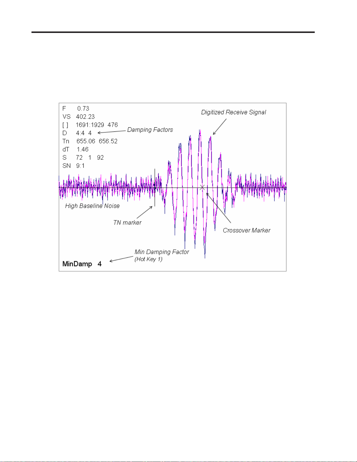
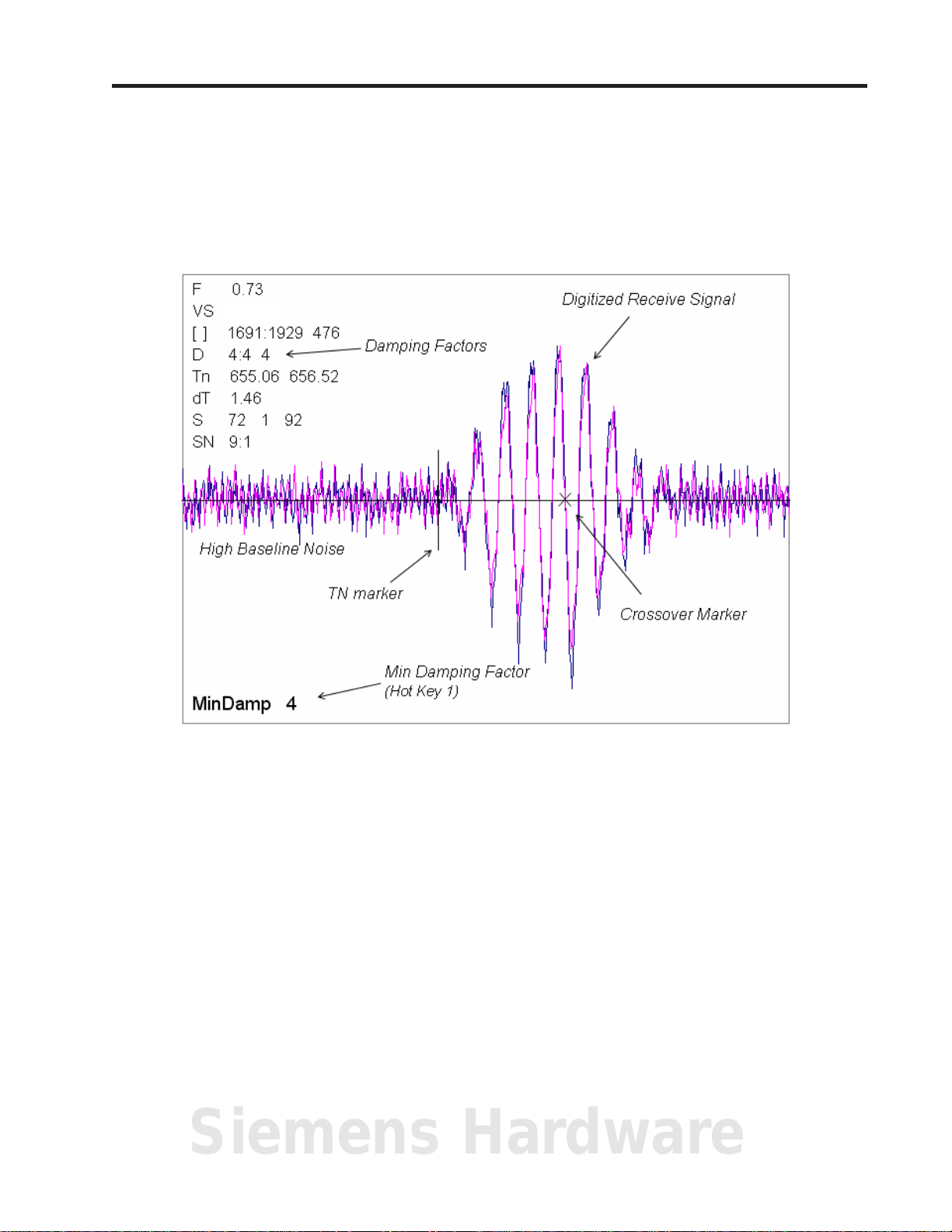
z The Test Facilities Graphic Screen will appear on the meter display as shown below.
Setting the Digital Damping Factor to a value HIGHER than the default value of 4 may be necessary
in cases where the signal to noise ratio (SN) is found to be unacceptably low (<15:1), but only if the
noise is determined to be asynchronous (i.e., not associated with the transmit or flowmeter timing
circuitry) as shown in the signal example above, where the baseline noise has a higher frequency
than the true gas signal.
The following application conditions may require a higher Digital Damping Factor:
z Close proximity to pressure control valves which may generate in-band acoustic noise
z Very low acoustic signal levels (ALC < 40%)
z High electronic noise from variable frequency drives or other external equipment.
A-2
Manual Addendum
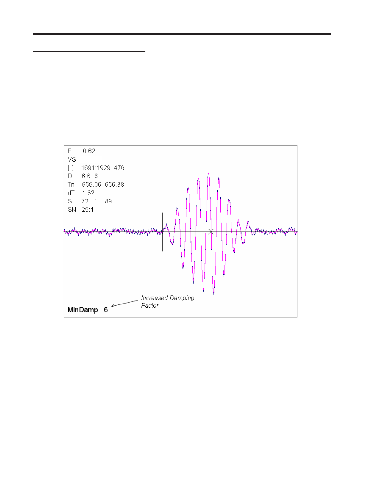
To INCREASE the Digital Damping:
1. Press the <1> key while viewing the Test Facilities Graph Screen as shown above. The damping
control [MinDamp #] should appear on the command line at the lower left-hand corner of the
screen.
Note: The number listed to the right of the command code on the screen represents the
exponent in the exponential averaging routine, where the larger the number represents
the greater the digital averaging. Setting this exponent higher than 7 is generally not
recommended.
2, Pressing the <+> key will increase the MinDamp Factor by one unit for each key press. To exit this
mode, press the <0> key on the keypad.
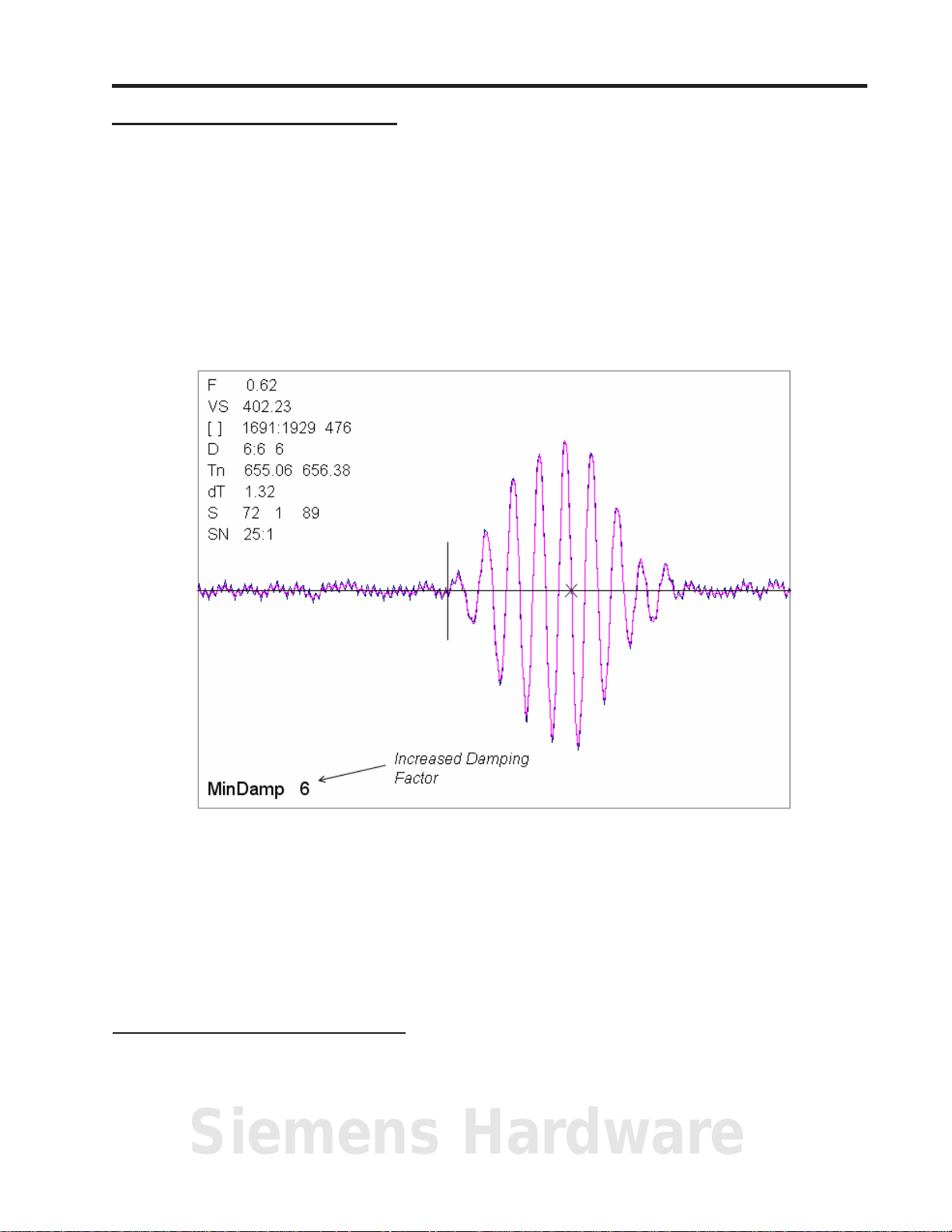
1010FMA-58
The above example shows that increasing the Digital Damping reduces asynchronous noise.
Setting the Digital Damping factor to a value LOWER than the default value of 4 may be justified in
cases where pulsating flow is present (such as from a reciprocating compressor) or for the purpose
of diagnosing transient signal behavior. A pulsating flow condition that generates more than +/- 45
degrees of phase jitter will generally cause signal correlation problems when any digital averaging is
used. In this case it may be necessary to completely eliminate the digital averaging by reducing the
Digital Damping Factor to 0. In such a case it may also be necessary to install a narrow band tuned
amplifier (Input Module) if too much asynchronous noise exists.
To DECREASE the Digital Damping:
1. Press the <2> key while viewing the Test Facilities Graph Screen. The damping control [MaxDamp
#] should appear on the command line at the lower left-hand corner of the screen.
2. Pressing the <-> key will decrease the MaxDamp Factor by one unit for each key press. To exit this
mode, press the <0> key on the keypad.
Siemens Hardware
A-3

Manual Addendum
Liquid Clamp-on Flowmeter Manuals
Replace the Digital Damping Control: (Hot Key 1 and 2) procedure in the “Detection Modes” section
(sub-paragraph: Command Modes) in the following flowmeter manuals:
FUS1010 IP 65 (NEMA 4X) Clamp-On Flowmeter manual (CQO:1010NFM-3)
FUE1010 IP 65 (NEMA 4X) Clamp-On Flowmeter manual (CQO:1010ENFM-3)
FUH1010 IP 65 (NEMA 4X) Clamp-On Flowmeter manual (CQO:1010DVNFM-3)
FUH1010 IP 65 (NEMA 4X) Clamp-On Flowmeter manual (CQO:1010PVNFM-3)
FUP1010 IP 40 (NEMA 1) Clamp-On Portable Flowmeter manual (CQO:1010PFM-3)
FUE1010 IP 40 (NEMA 1) Clamp-On Portable Flowmeter manual (CQO:1010EPFM-3)
Digital Damping Control: (Hot Key 1 and 2)
The meter permits user modification of the digital averaging used by the signal processing routines. In
general, the default damping values selected by the METER will provide optimal performance over a
wide range of transit time applications. However, in extreme cases of unstable flow, pulsating flow, low
signal levels or high electronic noise it may be necessary to override these default settings to permit
uninterrupted and reliable flow measurement.
1010FMA-58
Test Facilities Graph Screen
The Graph Screen includes the capability to access a set of command codes, which enable a user to
override a number of default meter settings. The most important parameter is the digital damping
control, which can be accessed by pressing number <1> or <2> on the keypad while in the Signal
Graph Screen mode.
[MinDamp] Command
Pressing the <1> key will cause [MinDamp #] to appear on the command line at the lower left-hand
corner of the screen. The number listed to the right of the command code represents the exponent in
the meter exponential averaging routine, where the larger the number the greater the digital averaging.
Pressing the <+> key will increase the damping value. Likewise, pressing the <-> key will decrease
the damping value. To exit this mode, press the <0> key on the keypad.
[MaxDamp] Command
Pressing the <2> key will bring up the [MaxDamp] command. The function of this parameter is similar
to the [MinDamp] command described above; however, the two parameters interact in the following
manner. The MinDamp value must not exceed the MaxDamp value, therefore increasing the MinDamp
value above the previous MaxDamp value will set both parameters to the same value. In most cases,
it is preferred that both damping parameters be set to the same value, however, in cases where rapid
response to changes in liquid sound velocity for flow rate is required, the two values may be set
differently. In this situation the meter will use the MaxDamp value when conditions are stable, but then
switch to a faster damping value (limited by MinDamp) when a significant change in sound velocity or
flow rate is perceived. To exit this mode, press the <0> key on the keypad.
A-4
Manual Addendum
To access the Digital Damping Control using the Test Facilities Graph Screen, proceed as follows:
1. To use the Test Facilities Graph Screen you must have a working site.
2. To activate the Test Facilities Graph Screen:
z In the main menu, scroll to the [Diagnostic Data] menu and select [Test Facilities].
z Scroll down to [Graph], press the <Right Arrow> and highlight [Yes]. Press <ENT> to select.
z The Test Facilities Graphic Screen will appear on the meter display as shown below.
1482.1
1010FMA-58
Setting the Digital Damping Factor to a value HIGHER than the default value of 4 may be necessary in
cases where the signal to noise ratio (SN) is found to be unacceptably low (<15:1), but only if the noise
is determined to be asynchronous (i.e., not associated with the transmit or flowmeter timing circuitry)
as shown in the signal example above, where the baseline noise has a higher frequency than the true
liquid signal.
The following application conditions may require a higher Digital Damping Factor:
z Close proximity to pressure control valves which may generate in-band acoustic noise
z High un-dissolved gas solids content in liquid.
z High electronic noise from variable frequency drives or other external equipment.
Siemens Hardware
A-5
Manual Addendum
1010FMA-58
To INCREASE the Digital Damping:
1. Press the <1> key while viewing the Test Facilities Graph Screen as shown above. The damping
control [MinDamp #] should appear on the command line at the lower left-hand corner of the
screen.
Note: The number listed to the right of the command code on the screen represents the
exponent in the exponential averaging routine, where the larger the number represents
the greater the digital averaging. Setting this exponent higher than 7 is generally not
recommended.
2. Pressing the <+> key will increase the MinDamp Factor by one unit for each key press. To exit this
mode, press the <0> key on the keypad.
1482.1
The above example shows that increasing the Digital Damping reduces asynchronous noise.
Setting the Digital Damping factor to a value LOWER than the default value of 4 may be justified in
cases where pulsating flow is present (such as from a reciprocating pump) or for the purpose of
diagnosing transient signal behavior. A pulsating flow condition that generates more than +/- 45 degrees
of phase jitter will generally cause signal correlation problems when any digital averaging is used. In
this case it may be necessary to completely eliminate the digital averaging by reducing the Digital
Damping Factor to 0.
To DECREASE the Digital Damping:
1. Press the <2> key while viewing the Test Facilities Graph Screen. The damping control [MaxDamp
#] should appear on the command line at the lower left-hand corner of the screen.
2. Pressing the <-> key will decrease the MaxDamp Factor by one unit for each key press. To exit this
mode, press the <0> key on the keypad.
A-6

1010BXFM-3 Table Of Contents
TABLE OF CONTENTS
Section 1
1. Introduction ........................................................................................................ 1-1
1.1 Important Safety Considerations ................................................................... 1-1
1.2 Interface Detector Installation Steps ............................................................ 1-1
1.3 System Hardware Description ........................................................................ 1-2
Specifications.................................................................................................... 1-2
1.4 Standard Features ............................................................................................. 1-2
Integral Datalogger .......................................................................................... 1-3
Analog Outputs ................................................................................................ 1-3
1.5 Introduction To The 1010BX Operating System ......................................... 1-3
1.5.1 Installation Menu Overview ............................................................................ 1-3
1.5.2 Overview Of Real-Time Data Collection....................................................... 1-3
1.6 Description Of Channel Functions (1010 DBX Systems only) ................. 1-4
Dual Channel ................................................................................................... 1-4
Dual Path ......................................................................................................... 1-4
1.7 Power Connections ............................................................................................ 1-5
1.7.1 Input Power Connector (P8) And Fuse (F1) Locations ............................. 1-5
1.7.2 Power Supply Wiring ........................................................................................ 1-5
1.8 The Menu Lockout Switch ............................................................................... 1-6
1.9 Interface Detector Installation Summary .................................................... 1-7
1.10 Choosing A Programming Interface .............................................................. 1-7
1.10.1 Overview Of The Magnetic Wand Interface................................................. 1-7
Typical 1010BX Interface Detector System ................................................... 1-8
1.10.2 Overview Of The RS-232 Interface ................................................................. 1-9
1.11 Installation Menu Operation With The Magnetic Wand ........................... 1-9
1.11.1 Accessing And Leaving The Menu ................................................................ 1-10
1.11.2 System 1010BX Installation Menu Structure ............................................ 1-11
1.11.3 How To Use The Magnetic Wand To Enter Data....................................... 1-14
How to Select Items from an Option List ..................................................... 1-15
A Note on Multiple Select Option Lists ........................................................ 1-16
How to Enter Numeric Data ......................................................................... 1-16
How to Enter Alphanumeric Strings .......................................................... 1-17
1.12 How To Use The RS-232 Interface To Enter Data ................................... 1-19
1.12.1 The RS-232 Interface Cable .......................................................................... 1-19
1.12.2 Establishing Communications Using HyperTerminal™ ........................ 1-19
1.12.3 Accessing The Installation Menu ................................................................. 1-21
Data Display Mode ....................................................................................... 1-22
1.12.4 Data Entry Using The RS-232 Interface .................................................... 1-22
Accessing and Leaving the Menu ................................................................ 1-22
1.13 Navigating Through The Installation Menu ............................................. 1-23
1.14 Using The 1010BX Reset Sequence ............................................................ 1-23
1.14.1 System Reset Using The Magnetic Wand .................................................. 1-24
1.14.2 System Reset Using The RS-232 Interface ................................................ 1-25
1.15 Introduction To The 1010BX Menu Screens ............................................. 1-26
Typical 1010BX Installation Menu Screen ................................................. 1-26
Explanations of Installation Menu Callouts .............................................. 1-26
1.16 Data Entry Procedures Using The RS-232 Interface ............................. 1-27
1.16.1 Entering Alphanumeric Strings ................................................................... 1-27
1.16.2 Selecting Items From An Option List ......................................................... 1-28
Sect./Page
Siemens Hardware
i

1010BXFM-3 Table Of Contents
Multiple Select Option Lists ....................................................................... 1-30
1.16.3 Entering Numeric Data .................................................................................. 1-30
1.17 How to Set Up A Channel For Transit-Time Operation ......................... 1-31
1.17.1 How To Access The Channel Setup Menu And Create A Site .............. 1-31
1.17.2 How To Enter Pipe Data................................................................................. 1-32
1.17.3 How To Select A Liquid Type ........................................................................ 1-33
1.17.4 How To Manually Select Transducers And A Mounting Mode ............ 1-34
Installing The Transducers .......................................................................... 1-36
Section 2
2. The 1010BX Installation Menu ........................................................................ 2-1
Review of Manual Conventions ....................................................................... 2-1
Review of Installation Menu Notes................................................................. 2-1
2.1 The Channel/Path Setup Menu ....................................................................... 2-2
2.1.1 How To Recall A Site Setup ............................................................................. 2-2
2.1.2 How To Enable And Disable A Measurement Channel ............................. 2-3
2.1.3 How To Use [Create/Name A Site] Setup ...................................................... 2-4
2.1.4 How To Enable/Disable Site Security ............................................................ 2-4
2.1.5 How To Delete A Site Setup ............................................................................. 2-5
2.1.6 How To Save/Rename A Site Setup ................................................................ 2-5
2.2 The Pipe Data Menu .......................................................................................... 2-6
The Pipe Data Menu Structure ....................................................................... 2-7
2.2.1 How To Select A Pipe Class.............................................................................. 2-8
2.2.2 How To Select A Pipe Size ................................................................................ 2-8
2.2.3 How To Enter The Pipe OD (in. or mm) ........................................................ 2-9
2.2.4 How To Select A Pipe Material ....................................................................... 2-9
2.2.5 How To Enter The Wall Thickness ................................................................. 2-9
2.2.6 Liner Material ................................................................................................... 2-10
2.2.7 Liner Thickness ................................................................................................ 2-10
2.3 The Application Data Menu ........................................................................... 2-10
Application Data Menu Structure ................................................................ 2-11
2.3.1 How To Select A Liquid Class ........................................................................ 2-12
How to Edit the [Estimated Vs m/s] (liquid sonic velocity) ......................... 2-13
How to Edit the [Viscosity cS] Setting.......................................................... 2-13
How to Edit the [Density SG] Setting .......................................................... 2-14
2.3.2 Activating The Liquid Table .......................................................................... 2-14
Setting the LiquIdent™ Slope....................................................................... 2-15
Setting the Pressure Slope ............................................................................ 2-15
Setting the Reference Base Temperature..................................................... 2-16
Entering K0 and K1 Parameters (API thermal expansion coefficients) .... 2-16
Setting the LiquIdent™ Index ...................................................................... 2-17
Index Value............................................................................................... 2-18
S.G............................................................................................................. 2-18
Viscosity .................................................................................................... 2-18
Visc Slope .................................................................................................. 2-18
Liquid Name ............................................................................................. 2-18
K0 and K1 ................................................................................................. 2-18
2.3.3 How To Select A Pipe Temperature Range ............................................... 2-19
2.3.4 Pipe Configuration .......................................................................................... 2-19
Pipe Configuration Option List Definitions .............................................. 2-20
2.4 The Pick/Install XDCR (Transducer) Menu .............................................. 2-21
ii

1010BXFM-3 Table Of Contents
Pick/Install Xdcr Menu Structure ............................................................... 2-22
2.4.1 How To Select A Transducer Model ............................................................ 2-23
2.4.2 How To Select A Transducer Size ................................................................ 2-23
2.4.3 How To Select A Transducer Mounting Mode .......................................... 2-23
2.4.4 Reviewing The Spacing Method ................................................................... 2-24
2.4.5 How To Use The Spacing Offset ................................................................... 2-24
2.4.6 Letter Index (1011 Transducer) - Letter and Number Index (990 Trans-
ducer ................................................................................................................... 2-24
The 1011 Transducer .................................................................................... 2-24
The 990 Transducer ...................................................................................... 2-24
2.4.7 The Number Index Menu Cell ...................................................................... 2-24
2.4.8 The Ltn Value (in) ............................................................................................ 2-24
2.4.9 How To Use [Install Complete?] .................................................................. 2-26
Installation Notes ......................................................................................... 2-26
Force Transmit Procedure ........................................................................... 2-27
2.4.10 The Empty Pipe Set Menu ............................................................................. 2-30
How to Use the Actual MTY Command...................................................... 2-30
How to Use the MTYmatic Command ........................................................ 2-30
How to Use the Set Empty Command ........................................................ 2-31
2.5 The Operation Adjust Menu .......................................................................... 2-31
2.5.1 Memory/Fault Set ............................................................................................. 2-32
2.5.2 Memory Delay (sec) ......................................................................................... 2-32
2.5.3 Sonilocator Operation ..................................................................................... 2-32
Using the [Sonilocate] Menu Item ............................................................... 2-33
2.6 The Data Span/Set/Cal Menu ........................................................................ 2-35
The Data Span/Set/Cal Menu Structure ..................................................... 2-35
2.6.1 Span Data ........................................................................................................... 2-36
Max LiquIdent ............................................................................................... 2-36
Min LiquIdent................................................................................................ 2-36
Max ROC ........................................................................................................ 2-36
Min ROC ........................................................................................................ 2-37
Max Vs m/s ..................................................................................................... 2-37
Min Vs m/s ..................................................................................................... 2-37
Max S.G. ......................................................................................................... 2-37
Min S.G. .......................................................................................................... 2-37
Max API .......................................................................................................... 2-37
Min API .......................................................................................................... 2-37
Max Kg/m3...................................................................................................... 2-37
Min Kg/m3...................................................................................................... 2-37
Max Base S.G. ................................................................................................ 2-37
Min Base S.G. ................................................................................................ 2-37
Max Base API ................................................................................................ 2-37
Min Base API ................................................................................................. 2-38
Max Base Kg/m3............................................................................................. 2-38
Min Base Kg/m3............................................................................................. 2-38
Max Viscosity cS ............................................................................................ 2-38
Min Viscosity cS ............................................................................................ 2-38
Max Temperature ......................................................................................... 2-38
Min Temperature .......................................................................................... 2-38
2.6.2 Set Alarm Levels .............................................................................................. 2-38
Siemens Hardware
iii

1010BXFM-3 Table Of Contents
High S.G. ........................................................................................................ 2-38
Low S.G. ......................................................................................................... 2-39
High API ........................................................................................................ 2-39
Low API .......................................................................................................... 2-39
High Kg/m3..................................................................................................... 2-39
Low Kg/m3...................................................................................................... 2-39
High Base S.G. ............................................................................................... 2-39
Low Base S.G. ................................................................................................ 2-39
High Base API ............................................................................................... 2-39
Low Base API ................................................................................................ 2-39
High Base Kg/m3........................................................................................... 2-40
Low Base Kg/m3............................................................................................. 2-40
High Viscosity cS .......................................................................................... 2-40
Low Viscosity cS ............................................................................................ 2-40
High Temperature ........................................................................................ 2-40
Low Temperature ......................................................................................... 2-40
Aeration % ..................................................................................................... 2-40
Makeup Latch ................................................................................................ 2-40
2.6.3 Interface Alarms .............................................................................................. 2-41
ROC Alm Set m/s ........................................................................................... 2-41
Interval Secs m/s ........................................................................................... 2-41
Relay Hold Time ........................................................................................... 2-41
High LiquIdent .............................................................................................. 2-41
Low LiquIdent ............................................................................................... 2-41
2.7 The Datalogger Setup Menu ......................................................................... 2-42
2.7.1 Datalogger Mode .............................................................................................. 2-43
2.7.2 Datalogger Data ............................................................................................... 2-43
The Datalogger Setup Menu Structure ...................................................... 2-43
Datalogger Data Option List ....................................................................... 2-44
Alarm Letter Codes and Descriptions ........................................................ 2-44
2.7.3 Log Time Interval ............................................................................................ 2-45
2.7.4 Datalogger Events ........................................................................................... 2-45
2.8 The I/O Data Control Menu ........................................................................... 2-46
The I/O Data Control Menu Structure ....................................................... 2-46
2.8.1 Analog Out Setup ............................................................................................. 2-47
System 1010 Analog Outputs ....................................................................... 2-47
Analog Out Setup Data Categories ............................................................. 2-47
Assigning Io Output Functions.................................................................... 2-48
Assigning Pgen Output Functions .............................................................. 2-48
2.8.2 Relay Setup ........................................................................................................ 2-48
Assigning Relay 1 Functions ........................................................................ 2-49
Relay Option List .......................................................................................... 2-49
2.8.3 Analog Input Setup (optional function) ...................................................... 2-50
Setting up the Analog Current Input ......................................................... 2-50
2.9 The Diagnostics Data Menu .......................................................................... 2-51
The Diagnostic Data Menu Structure ......................................................... 2-51
2.9.1 Main Diagnostics Screen ................................................................................ 2-52
Diagnostic Main Menu Description ............................................................ 2-52
2.9.2 Path Select ......................................................................................................... 2-52
2.9.3 Path Enable (N/A) ............................................................................................. 2-53
iv

1010BXFM-3 Table Of Contents
2.9.4 Path Data ............................................................................................................ 2-53
Path Data Menu Items.................................................................................. 2-53
Vs m/s ............................................................................................................. 2-54
AnCal .............................................................................................................. 2-54
2.9.5 The Application Info Menu ........................................................................... 2-55
Application Info Menu Items ....................................................................... 2-55
2.9.6 The Liquid Data Menu .................................................................................... 2-55
Liquid Data Menu Items .............................................................................. 2-56
2.9.7 The Site Setup Data Menu ............................................................................. 2-56
Site Setup Menu Items ................................................................................. 2-56
2.9.8 The Test Facilities Menu ................................................................................ 2-57
Test Facilities Commands ............................................................................ 2-57
Makeup........................................................................................................... 2-58
2.10 Troubleshooting Tips ...................................................................................... 2-58
2.10.1 Computer Messages ........................................................................................ 2-58
2.10.2 Troubleshooting With Transducer Test Blocks ....................................... 2-60
Using The 1012TB-1 and -2 Test Blocks ..................................................... 2-60
2.10.3 Using The 996PSP Pipe Simulator .............................................................. 2-62
If a Pipe Simulator/Test-Block Test Fails .................................................. 2-63
Section 3
3. Hardware Installation Guide .......................................................................... 3-1
3.1 Mounting The 1010BX Interface Detector .................................................... 3-1
3.2 Input/Output Wiring .......................................................................................... 3-2
3.2.1 1010BX Input/Output Wiring (TB1 and TB2) ............................................... 3-2
3.2.2 1010BDX Input/Output Wiring (TB1 and TB2) ............................................ 3-3
3.3 Preparing To Mount The Transducers.......................................................... 3-4
3.3.1 How To Identify 1011 Transducers And Mounting Hardware ................ 3-4
3.3.2 Selecting A Location For Clamp-On Transducers ...................................... 3-4
3.3.3 Clamp-On Transducer Mounting Modes ...................................................... 3-5
3.3.4 Preparing The Pipe ............................................................................................ 3-6
3.3.5 Sonic Coupling Compound Recommendations ........................................... 3-7
3.3.6 Reflect Mode With EZ Clamp and Spacer Bar Only ................................... 3-8
3.3.7 Direct Mode With EZ Clamp and Spacer Bar Only .................................... 3-9
3.3.8 Reflect Mode - Mounting Frames And Spacer Bar ................................... 3-13
3.3.9 Reflect Mode With Spacer Bar Only ............................................................ 3-14
3.3.10 Direct Mode-Mounting Frames, Spacer Bar And Spacing Guides. ...... 3-16
3.3.11 Using 1012T Mounting Tracks ....................................................................... 3-20
Installing A 1012T Mounting Track In Reflect Mode .................................. 3-20
Installing A 1012T Mounting Track In Direct Mode ................................... 3-22
3.4 Temperature Sensors (optional) ................................................................... 3-24
3.4.1 991T Clamp-On Temperature Sensor........................................................... 3-24
3.4.2 991TW Thermowell Temperature Sensor ................................................... 3-24
3.5 Notes On System 1010 Analog Input Modules ........................................... 3-25
3.6 Clamp-On Resistive Temperature Device Installation Notes ................ 3-25
Section 4
4. The Meter Facilities Menu ............................................................................... 4-1
4.1 Preferred Units ................................................................................................... 4-1
4.2 The Table Setups Menu ..................................................................................... 4-2
Siemens Hardware
v

1010BXFM-3 Table Of Contents
4.2.1 Pipe Table ............................................................................................................ 4-2
Pipe Table Menu Structure ............................................................................ 4-2
4.2.2 Create/Edit Pipe ................................................................................................. 4-3
4.2.3 Delete Pipe .......................................................................................................... 4-4
4.3 Transducer Type Menu .................................................................................... 4-4
Transducer Type Menu Structure ................................................................. 4-5
4.4 The Datalogger Control Menu ........................................................................ 4-6
Datalogger Control Menu Structure ............................................................. 4-6
4.4.1 Output Datalogger ............................................................................................. 4-7
4.4.2 Circular Memory ................................................................................................ 4-7
4.4.3 Est Log Time Left ............................................................................................... 4-8
4.4.4 Clear Datalogger ................................................................................................ 4-8
4.5 The Memory Control Menu ............................................................................. 4-8
Memory Control Menu Structure.................................................................. 4-8
4.5.1 The Analog Output Trim Menu ....................................................................... 4-9
Analog Output Trim Menu Structure ........................................................... 4-9
4.5.2 Current Output Trim (Io1 & Io2) ................................................................... 4-9
4.5.3 Pgen Output Trim (Single Channel model only) ........................................ 4-9
4.6 The RTD Calibrate Menu (optional) ........................................................... 4-10
RTD Calibrate Menu Structure ................................................................... 4-10
4.6.1 The RTD Calibration By Data Entry ........................................................... 4-10
4.6.2 Ice Bath RTD Calibration .............................................................................. 4-11
4.7 The Clock Set Menu ........................................................................................ 4-11
Clock Set Menu Structure ............................................................................ 4-11
4.7.1 Date ..................................................................................................................... 4-12
4.7.2 Time ..................................................................................................................... 4-12
4.8 RS-232 Setup ..................................................................................................... 4-12
RS-232 Menu Structure ................................................................................ 4-13
4.8.1 Baud Rate ........................................................................................................... 4-13
4.8.2 Parity ................................................................................................................... 4-13
4.8.3 Data Bits ............................................................................................................. 4-14
4.8.4 Line Feed ........................................................................................................... 4-14
4.8.5 Network ID ........................................................................................................ 4-14
4.8.6 RTS Key Time .................................................................................................... 4-15
4.9 System Info ........................................................................................................ 4-15
System Info Menu Structure ........................................................................ 4-15
4.10 Data Display Screen ........................................................................................ 4-15
4.10.1 Activating The Display.................................................................................... 4-15
4.10.2 Selecting Display Data Items ........................................................................ 4-16
Section 5
5. System 1010BX Application Notes.................................................................. 5-1
5.1 To Obtain Technical Assistance...................................................................... 5-1
5.2 Pipe Considerations For Clamp-On Transducers ...................................... 5-1
5.2.1 Pipe Dimensions ................................................................................................. 5-1
5.2.2 Picking The Appropriate Transducer ........................................................... 5-2
5.3 Overview Of System Performance ................................................................. 5-2
5.3.1 Accuracy ............................................................................................................... 5-2
5.3.2 Repeatability ....................................................................................................... 5-2
5.3.3 Data Stability ...................................................................................................... 5-2
Data Scatter ..................................................................................................... 5-2
vi

1010BXFM-3 Table Of Contents
Data Drift ......................................................................................................... 5-3
5.4 Aeration ................................................................................................................ 5-3
5.5 Slurries ................................................................................................................. 5-3
5.6 Two-Phase Liquids ............................................................................................ 5-3
5.7 Viscous Liquids ................................................................................................... 5-3
5.8 Temperature And Pressure Ratings ............................................................. 5-4
5.9 Overview Of System 1010BX Memory Resources ..................................... 5-4
5.10 Reference Tables ............................................................................................... 5-5
Sonic Velocity (m/s) For Common Liquids @ 68ºF ....................................... 5-5
Sonic Velocity For Pure Water @ Various Temp. (m/s) .............................. 5-5
Vps Values (inches/sec) For Some Common Metals .................................... 5-6
Terminology Chart .......................................................................................... 5-7
5.11 The Dual Channel Menu Chart ...................................................................... 5-9
The Meter Type Menu .................................................................................... 5-9
The Meter Facilities Menu ............................................................................ 5-9
The Dual Channel Menu .............................................................................. 5-10
APPENDICES
Appendix A - Engineering Drawings ....................................................................................A-1
Index
Pipe Table
Siemens Hardware
vii


1010BXFM-3Section 1
1. INTRODUCTION
Congratulations on your purchase of the System 1010BX Interface Detector. The System 1010BX
is a compact NEMA-7/EExd-rated explosion-proof Interface Detector. Intended for dedicated
applications, this versatile meter is easy to set up and operate. The 1010BX represents the
state-of-the-art in computerized instrumentation. We are confident that in a very short time,
you will appreciate its unrivaled performance and features; especially Controlotron’s ground
breaking enhanced transit-time Digitally Coded MultiPulse™ technology and the on-line automatic and interactive site setup help facility.
This section explains how to install the System 1010BX Interface Detector with a minimum of
effort. It also will illustrate how to use the Installation Menu to set up the system and explain
the basic connections to and from the instrument. For additional information on connections,
see the drawings at the end of manual.
1.1 IMPORTANT SAFETY CONSIDERATIONS
The System 1010BX Interface Detector operates from either an external AC or DC power
source. Please observe all the electrical safety codes, etc., that apply to your application. We
recommend that only experienced personnel with knowledge of local electrical codes and safety
operating procedures perform the installation and wiring. It is solely the user’s responsibility
to operate this equipment safely. Controlotron cannot accept responsibility for any damage
that may occur due to failure to observe any local safety rules.
If this equipment is used for a hazardous application (high line pressure, hostile liquid characteristics, perilous atmosphere, etc.), the end-user must ensure that only properly trained personnel are involved in its installation and operation.
Please do not let the size of the Installation Menu intimidate you. Almost all menu cells already contain default parameters. To begin operation, you only need to access the menu cells
that control a required parameter, such as the pipe outer diameter. You will see that by accepting most defaults, you can set up the meter in about five minutes.
1.2 INTERFACE DETECTOR INSTALLATION STEPS
The following are typical steps to complete the installation procedure.
z Collect the site data (pipe and liquid data, part numbers, etc.).
z Choose a mounting location for the Interface Detector and transducers.
z Mount the Interface Detector at the selected location.
z Prepare pipe for transducer mounting.
z Access the Installation Menu and create a site (see paragraph 1.16.1).
z Enter pipe parameters (see paragraph 2.2).
z Invoke transducer install procedure (see paragraph 2.4).
z Mount transducers on pipe and connect to Interface Detector (see Section 3).
z Complete transducer install menu operation (see paragraph 2.4).
Siemens Hardware
1-1

1010BXFM-3Section 1
1.3 SYSTEM HARDWARE DESCRIPTION
System 1010BX is housed inside a cylindrical explosion-proof NEMA-7 aluminum, epoxy painted
case. The main metering compartment front and rear sections are sealed with an O-Ring with
separate threaded covers. The front section houses the main electronics and the optional
Magnetic Touch-Panel User Interface with a 2x16 character LCD Alphanumeric Display viewable through a tempered glass window. The rear section contains terminal blocks for the fused
power input and data I/O wiring. The primary instrumentation output is an isolated 4-20 mA
current loop. The meter includes a conventional RS-232 I/O port.
The main metering compartment is connected to the secondary housing by an aluminum pipe
that provides a pass-through for flow transducer and temperature sensor cabling. The secondary housing provides screw-on wire clamp terminals for flow and temperature sensors. To
maintain the NEMA-7 explosion-proof rating, all cabling and the transducer physical and electrical design must be in compliance with hazardous area specifications.
SPECIFICATIONS
Temperature: Operating Temperature
Operational and Storage Electronics: 14ºF to 122ºF (-10ºC to 50ºC)
LCD display: 14ºF to 122ºF (-10ºC to 50ºC)
Storage Temperature
Electronics: -4ºF to 140ºF (-20ºC to 60ºC)
*T ransducers temperature ratings depend on the individual
transducer type(s).
Power Consumption 110/220 VAC, less than 10 watts.
G-Force Rating Instrument survives 3’ drop onto 1” plywood (standard indus-
trial drop test). Mechanical design supports operation in a high
vibration environment.
For Hazardous Area Use Explosion-proof case designed for installation in Division 1/Zone
1 hazardous environments when installed per our instructions.
Agency approvals: CE (for EM) and FM/CENELEC pending. International approvals pending.
Provisions for User Menu Access Magnetic triggers (4-Arrows + Enter).
RS-232 interface for menu access and Datalogger dump.
Options Stainless Steel Case
Dial-up Modem
One RTD temperature sensing channel (measures clamp-on
liquid temperature
Blind System (programming vial serial link only)
1.4 STANDARD FEATURES
z Same features as the 1010 family of NEMA 4X flow computers except constructed in a
compact NEMA-7 explosion-proof housing.
z Flexible Setup options using either Magnetic Wand or a PC connected to RS-232 port.
z Integral 2x16 Character LCD panel display shows real-time data and Installation Menu
for Magnetic Wand programming.
z Flexible mounting - either on pipe or located up to 300 feet (100m) from the transducers.
For distances greater then 300 feet, please contact Controlotron Customer Service.
1-2
 Loading...