

Siemens SITRANS F FST030 Operating Instructions Manual

SITRANS F
Ultrasonic Flowmeters
FST030 (HART)
Operating Instructions
Edition
Answers for industry.
08/2017


SITRANS F
Ultrasonic flowmeters
SITRANS F Ultrasonic flowmeters
FST030 (HART)
Operating Instructions
These Operating Instructions apply to Siemens
SITRANS FST030 transmitters for use in flow meter
systems with order codes commencing 7ME372
08/2017
A5E35971532
Introduction
1
Safety notes
2
Description
3
Installing/Mounting
4
Connecting
5
Commissioning
6
Operating
7
Service and maintenance
8
Diagnosing and
troubleshooting
9
Technical data
10
Dimension drawings
11
Certificates and support
A
SIMATIC PDM
B
-AC
Siemens AG
Division Process Industries and Drives
Postfach 48 48
90026 NÜRNBERG
GERMANY
Document order number: A5E35971532
Ⓟ
Copyright © Siemens AG 2017.
All rights reserved
Legal information
Warning notice system
DANGER
indicates that death or severe personal injury will result if proper precautions are not taken.
WARNING
may
CAUTION
indicates that minor personal injury can result if proper precautions are not taken.
NOTICE
indicates that property damage can result if proper precautions are not taken.
Qualified Personnel
personnel qualified
Proper use of Siemens products
WARNING
Siemens products may only be used for the applications described in the catalog and in the relevant technical
maintenance are required to ensure that the products operate safely and without any problems. The permissible
ambient conditions must be complied with. The information in the relevant documentation must be observed.
Trademarks
Disclaimer of Liability
This manual contains notices you have to observe in order to ensure your personal safety, as well as to prevent
damage to property. The notices referring to your personal safety are highlighted in the manual by a safety alert
symbol, notices referring only to property damage have no safety alert symbol. These notices shown below are
graded according to the degree of danger.
indicates that death or severe personal injury
If more than one degree of danger is present, the warning notice representing the highest degree of danger will
be used. A notice warning of injury to persons with a safety alert symbol may also include a warning relating to
property damage.
result if proper precautions are not taken.
The product/system described in this documentation may be operated only by
task in accordance with the relevant documentation, in particular its warning notices and safety instructions.
Qualified personnel are those who, based on their training and experience, are capable of identifying risks and
avoiding potential hazards when working with these products/systems.
Note the following:
documentation. If products and components from other manufacturers are used, these must be recommended
or approved by Siemens. Proper transport, storage, installation, assembly, commissioning, operation and
All names identified by ® are registered trademarks of Siemens AG. The remaining trademarks in this publication
may be trademarks whose use by third parties for their own purposes could violate the rights of the owner.
We have reviewed the contents of this publication to ensure consistency with the hardware and software
described. Since variance cannot be precluded entirely, we cannot guarantee full consistency. However, the
information in this publication is reviewed regularly and any necessary corrections are included in subsequent
editions.
for the specific
08/2017 Subject to change

Table of contents
1 Introduction ............................................................................................................................................. 7
2 Safety notes .......................................................................................................................................... 13
3 Description ............................................................................................................................................ 21
4 Installing/Mounting ................................................................................................................................ 31
1.1 Product compatibility ................................................................................................................. 7
1.2 Document history ...................................................................................................................... 8
1.3 Device documentation package ................................................................................................ 8
1.4 Items supplied ........................................................................................................................... 9
1.5 Checking the consignment ....................................................................................................... 9
1.6 Security information ................................................................................................................ 10
1.7 Transportation and storage ..................................................................................................... 11
1.8 Notes on warranty ................................................................................................................... 11
2.1 Preconditions for safe use ...................................................................................................... 13
2.1.1 Improper device modifications ................................................................................................ 13
2.2 Laws and directives ................................................................................................................ 13
2.2.1 FCC Conformity ...................................................................................................................... 14
2.2.2 Conformity with European directives ...................................................................................... 14
2.3 Requirements for special applications .................................................................................... 15
2.4 Use in hazardous areas .......................................................................................................... 15
2.4.1 Use in hazardous areas .......................................................................................................... 16
2.4.2 Loss of safety of device with type of protection "Intrinsic safety Ex i" .................................... 16
2.4.3 Dust layers above 5 mm ......................................................................................................... 17
2.5 Installation in hazardous areas ............................................................................................... 18
3.1 Design ..................................................................................................................................... 21
3.1.1 Transmitter .............................................................................................................................. 21
3.2 Features .................................................................................................................................. 21
3.3 Applications ............................................................................................................................. 24
3.4 Approvals ................................................................................................................................ 24
3.5 HART communication ............................................................................................................. 25
3.5.1 Universal commands .............................................................................................................. 28
3.5.2 Common practice commands ................................................................................................. 29
4.1 Installation location requirements ........................................................................................... 31
4.2 Installation instructions............................................................................................................ 32
4.2.1 Wall mount enclosure transmitter ........................................................................................... 32
SITRANS F Ultrasonic flowmeters FST030 (HART)
Operating Instructions, 08/2017, A5E35971532-AC
3

Table of contents
5 Connecting ........................................................................................................................................... 35
6 Commissioning ..................................................................................................................................... 51
7 Operating .............................................................................................................................................. 69
5.1 Basic safety notes .................................................................................................................. 35
5.1.1 Missing PE/ground connection .............................................................................................. 35
5.1.2 Unsuitable cables, cable glands and/or plugs ....................................................................... 36
5.1.3 Lack of equipotential bonding ................................................................................................ 36
5.1.4 Unprotected cable ends ......................................................................................................... 36
5.1.5 Improper laying of shielded cables ........................................................................................ 37
5.1.6 Insufficient isolation of intrinsically safe and non-intrinsically safe circuits ............................ 37
5.1.7 Incorrect conduit system ........................................................................................................ 37
5.1.8 Energized devices .................................................................................................................. 38
5.2 Disconnecting device ............................................................................................................. 38
5.3 Device nameplates ................................................................................................................ 38
5.4 Transmitter power supply, communications and I/Os connection ......................................... 40
5.4.1 Sensor connections reference ............................................................................................... 40
5.4.2 Preparing for the connections ................................................................................................ 41
5.4.3 Terminal layout....................................................................................................................... 42
5.4.4 Connecting channel 1 ............................................................................................................ 43
5.4.5 Connecting channels 2 to 4 ................................................................................................... 44
5.4.5.1 Input/output configuration ...................................................................................................... 46
5.4.6 Connecting channels 5 and 6 ................................................................................................ 47
5.4.7 Connecting the power supply ................................................................................................. 48
5.5 Finishing the transmitter connection ...................................................................................... 49
6.1 Basic safety notes .................................................................................................................. 51
6.1.1 Opening device in energized state......................................................................................... 51
6.2 General requirements ............................................................................................................ 52
6.3 Power-up ................................................................................................................................ 52
6.4 Local display .......................................................................................................................... 52
6.5 Initial startup ........................................................................................................................... 53
6.6 Commissioning via local display ............................................................................................ 54
6.6.1 Wizards .................................................................................................................................. 54
6.6.1.1 Wizard overview ..................................................................................................................... 54
6.6.1.2 Quick commissioning wizard .................................................................................................. 55
6.6.1.3 Sensor settings wizard ........................................................................................................... 56
6.6.1.4 Process values wizard ........................................................................................................... 60
6.6.1.5 Inputs and outputs wizard ...................................................................................................... 62
6.6.2 Navigating the menu structure ............................................................................................... 67
6.6.2.1 Navigation view ...................................................................................................................... 67
7.1 Operating via the local display ............................................................................................... 69
7.1.1 Display views ......................................................................................................................... 69
7.1.2 Access control ........................................................................................................................ 69
7.2 Operating the FST030 ........................................................................................................... 70
7.2.1 Fixed display texts ................................................................................................................. 70
7.2.2 Reading the process values ................................................................................................... 72
SITRANS F Ultrasonic flowmeters FST030 (HART)
4 Operating Instructions, 08/2017, A5E35971532-AC

Table of contents
8 Service and maintenance ...................................................................................................................... 81
9 Diagnosing and troubleshooting ............................................................................................................ 85
10 Technical data .................................................................................................................................... 113
11 Dimension drawings ............................................................................................................................ 121
A Certificates and support ...................................................................................................................... 123
7.2.3 Operating the totalizers ........................................................................................................... 74
7.2.4 Handling alarms ...................................................................................................................... 75
7.2.5 Reading the diagnostic values ................................................................................................ 76
7.3 Reading / changing parameters .............................................................................................. 76
7.3.1 Alphanumeric parameters ....................................................................................................... 76
7.3.1.1 Changing the resolution .......................................................................................................... 78
7.3.2 Parameter lists ........................................................................................................................ 78
8.1 Basic safety notes ................................................................................................................... 81
8.1.1 Impermissible repair of explosion protected devices .............................................................. 81
8.2 Recalibration ........................................................................................................................... 81
8.3 Cleaning .................................................................................................................................. 82
8.4 Electrostatic charge ................................................................................................................ 82
8.5 Maintenance and repair work ................................................................................................. 82
8.5.1 Service and maintenance information .................................................................................... 82
8.6 Return procedure .................................................................................................................... 83
8.7 Disposal .................................................................................................................................. 84
9.1 Unexpected behavior .............................................................................................................. 85
9.2 Application questionnaire ........................................................................................................ 87
9.3 Device status icons ................................................................................................................. 88
9.4 Fault codes and corrective actions ......................................................................................... 90
10.1 Power .................................................................................................................................... 113
10.2 HART interface ..................................................................................................................... 113
10.3 Inputs .................................................................................................................................... 114
10.4 Outputs ................................................................................................................................. 115
10.5 Construction .......................................................................................................................... 117
10.6 Operating conditions ............................................................................................................. 118
10.7 Approvals .............................................................................................................................. 119
10.8 SensorFlash .......................................................................................................................... 120
11.1 Transmitter ............................................................................................................................ 121
A.1 Certificates ............................................................................................................................ 123
A.2 Technical support .................................................................................................................. 123
A.3 QR code label ....................................................................................................................... 124
SITRANS F Ultrasonic flowmeters FST030 (HART)
Operating Instructions, 08/2017, A5E35971532-AC
5

Table of contents
B SIMATIC PDM ..................................................................................................................................... 125
Index ................................................................................................................................................... 137
B.1 Commissioning with SIMATIC PDM .................................................................................... 125
B.1.1 Operating via SIMATIC PDM ............................................................................................... 125
B.1.2 Functions in SIMATIC PDM ................................................................................................. 125
B.1.3 Supported SIMATIC PDM versions ..................................................................................... 125
B.1.4 Initial setup ........................................................................................................................... 126
B.1.5 Integrating the EDD ............................................................................................................. 126
B.1.6 Integrating a HART device in a HART modem network ...................................................... 127
B.1.7 Configuring a new device ..................................................................................................... 130
B.1.8 Wizard - Quick Start via PDM .............................................................................................. 130
B.1.9 Wizard - Clamp-On Configuration ........................................................................................ 131
B.1.10 Wizard - Zero point adjustment ............................................................................................ 132
B.1.11 Changing parameter settings using SIMATIC PDM ............................................................ 132
B.1.12 Parameters accessed via drop-down menus ....................................................................... 133
B.1.13 Process variables ................................................................................................................. 135
B.2 Diagnosing with PDM ........................................................................................................... 136
SITRANS F Ultrasonic flowmeters FST030 (HART)
6 Operating Instructions, 08/2017, A5E35971532-AC

1
Note
This manual applies to the SITRANS FST030 transmitter HART version only. HART
registered trademark of the HART Communication Foundation.
1.1
Product compatibility
Document
edition
Remarks
Device revision
Compatible version of device integration package
SIMATIC PDM V8.2 or later
EDD: 1.00.00 or later
later
Field communicator V3.8
EDD: 1.00.00 or later
later
SITRANS DTM V4.1
EDD: 1.00.00 or later
Field communicator V3.8
EDD: 1.00.00 or later
®
is a
In order to operate an ultrasonic flow meter, you need both the transmitter Operating
Instructions and the sensor Installation Manual, see Flow documentation
(https://support.industry.siemens.com/cs/ww/en/ps/17317
).
08/2017 New document
edition
02/2017 First edition HART
HART
FW: 1.00.00
HW: 02
Device revision 1 or later
FW:1.00.00
HW: 02
Device revision 1 or later
AMS Device Manager 12.0 or
SITRANS DTM V4.1 EDD: 1.00.00 or later
SIMATIC PDM V8.2 or later
AMS Device Manager 12.0 or
EDD: 1.00.00 or later
EDD: 1.00.00 or later
EDD: 1.00.00 or later
SITRANS F Ultrasonic flowmeters FST030 (HART)
Operating Instructions, 08/2017, A5E35971532-AC
7

Introduction
1.2
Document history
Edition
Note
Chapter: Safety notes. Use in hazardous areas. Special conditions for safe use. Added: Must be installed
1.3
Device documentation package
Document
Purpose
Intended users
Availability
1.2 Document history
The following table shows major changes in the documentation compared to the previous
edition.
The most important changes in the documentation when compared with the respective
previous edition are given in the following table.
08/2017
02/2017
•
in accordance with Siemens control drawing A5E32778336A.
• First edition
The user documentation package for this product includes the following documents
Operating Instructions
Compact Operating
Instructions - Ex
Functions Manual Contains
Contains all information needed to
• check and identify the delivered pack-
age
• install and electrically connect the
product
• commission the product, (setting pa-
rameters via HMI menu)
• operate and maintain the device on a
daily basis
• troubleshoot and remedy minor opera-
tion interruptions
Contains all information needed to
• satisfy the Special conditions for instal-
lation of Ex-certified products
• descriptions of all functions that can be
accessed via the local display (HMI)
• guide to setting parameters to obtain
optimum operation of the device
Instrument technicians, plant operators
Instrument technicians, plant operators with special
training in systems
for hazardous areas.
Instrument technicians, plant operators
• Available for download from
homepage
• Hardcopy can be purchased
via PIA Life Cycle Portal
(only English and German
versions)
• On documentation disk
• Available for download from
homepage
• Hardcopy can be ordered
via PIA Life Cycle Portal
• Available for download from
homepage
SITRANS F Ultrasonic flowmeters FST030 (HART)
8 Operating Instructions, 08/2017, A5E35971532-AC

Introduction
1.4
Items supplied
Wall mount enclosure
With internal DSL (Digital Sensor Link)
•
•
Note
Supplementary information
Supplementary product and production specific certificates are included on the SensorFlash®
SD card in the transmitter socket.
Note
Scope of delivery may vary, depending on version and add
delivery and the information on the nameplate correspond to your order and the delivery
note.
Note
The SD
sold or imported in the United States. Products having enabled SD
functionality are intended to be used solely outside the United States and should not be
imported into the United States by the user. SIEMENS expressly
using, importing, or buying products with the SD
United States or performing any acts to enable the SD
products sold by SIEMENS with this feature disabled.
1.5
Checking the consignment
1.4 Items supplied
The device is delivered as:
SITRANS FST030 wall mount enclosure
transmitter with internal DSL
Siemens Process Instrumentation
documentation disk containing certificates,
and manuals for ATEX approved devices
-ons. Make sure the scope of
-Card Mass Storage functionality has been disabled by SIEMENS on all products
-Card Mass storage
prohibits customers from
-Card Mass Storage functionality in the
-Card Mass Storage functionality on
1. Check the packaging and the delivered items for visible damage.
2. Report any claims for damages immediately to the shipping company.
SITRANS F Ultrasonic flowmeters FST030 (HART)
Operating Instructions, 08/2017, A5E35971532-AC
9

Introduction
WARNING
Using a damaged or incomplete device
1.6
Security information
1.6 Security information
3. Retain damaged parts for clarification.
4. Check the scope of delivery by comparing your order to the shipping documents for
correctness and completeness.
Risk of explosion in hazardous areas. May cause death or serious injury.
• Do not use damaged or incomplete devices.
Siemens provides products and solutions with industrial security functions that support the
secure operation of plants, systems, machines, and networks.
In order to protect plants, systems, machines and networks against cyber threats, it is
necessary to implement – and continuously maintain – a holistic, state-of-the-art industrial
security concept. Siemens’ products and solutions only form one element of such a concept.
Customer is responsible to prevent unauthorized access to its plants, systems, machines
and networks. Systems, machines and components should only be connected to the
enterprise network or the internet if and to the extent necessary and with appropriate security
measures (e.g. use of firewalls and network segmentation) in place.
Additionally, Siemens’ guidance on appropriate security measures should be taken into
account. For more information about industrial security, please visit:
http://www.siemens.com/industrialsecurity.
Siemens’ products and solutions undergo continuous development to make them more
secure. Siemens strongly recommends to apply product updates as soon as available and to
always use the latest product versions. Use of product versions that are no longer supported,
and failure to apply latest updates may increase customer’s exposure to cyber threats.
To stay informed about product updates, subscribe to the Siemens Industrial Security RSS
Feed under
http://www.siemens.com/industrialsecurity.
SITRANS F Ultrasonic flowmeters FST030 (HART)
10 Operating Instructions, 08/2017, A5E35971532-AC
Introduction
1.7
Transportation and storage
NOTICE
Insufficient protection during storage
CAUTION
1.8
Notes on warranty
1.7 Transportation and storage
To guarantee sufficient protection during transport and storage, observe the following:
● Keep the original packaging for subsequent transportation.
● Devices/replacement parts should be returned in their original packaging.
● If the original packaging is no longer available, ensure that all shipments are properly
packaged to provide sufficient protection during transport. Siemens cannot assume
liability for any costs associated with transportation damages.
The packaging only provides limited protection against moisture and infiltration.
• Provide additional packaging as necessary.
Special conditions for storage and transportation of the device are listed in Technical data
(Page 113).
Protection of transmitter parts
The styrofoam parts in the transmitter are NOT packaging material.
• Do not remove styrofoam parts.
The contents of this manual shall not become part of or modify any prior or existing
agreement, commitment or legal relationship. The sales contract contains all obligations on
the part of Siemens as well as the complete and solely applicable warranty conditions. Any
statements regarding device versions described in the manual do not create new warranties
or modify the existing warranty.
The content reflects the technical status at the time of publishing. Siemens reserves the right
to make technical changes in the course of further development.
SITRANS F Ultrasonic flowmeters FST030 (HART)
Operating Instructions, 08/2017, A5E35971532-AC
11

Introduction
1.8 Notes on warranty
SITRANS F Ultrasonic flowmeters FST030 (HART)
12 Operating Instructions, 08/2017, A5E35971532-AC
2
2.1
Preconditions for safe use
Symbol
Explanation
2.1.1
Improper device modifications
WARNING
Improper device modifications
2.2
Laws and directives
This device left the factory in good working condition. In order to maintain this status and to
ensure safe operation of the device, observe these instructions and all the specifications
relevant to safety.
Observe the information and symbols on the device. Do not remove any information or
symbols from the device. Always keep the information and symbols in a completely legible
state.
Consult operating instructions
Risk of explosion in hazardous areas. May cause death or serious injury.
Risk to personnel, system and environment can result from modifications to the device,
particularly in hazardous areas.
• Only carry out modifications that are described in the instructions for the device. Failure
to observe this requirement cancels the manufacturer's warranty and the product
approvals.
SITRANS F Ultrasonic flowmeters FST030 (HART)
Operating Instructions, 08/2017, A5E35971532-AC
Observe the safety rules, provisions and laws applicable in your country during connection,
assembly and operation. These include, for example:
● National Electrical Code (NEC - NFPA 70) (USA)
● Canadian Electrical Code (CEC) (Canada)
13

Safety notes
2.2.1
FCC Conformity
US Installations only: Federal Communications Commission (FCC) rules
Note
•
•
2.2.2
Conformity with European directives
Electromagnetic
compatibility EMC
2014/30/EU
Directive of the European Parliament and of the Council on the harm
nisation of
compatibility
Low voltage d
rect
2014/35/EU
Directive of the European Parliament and of the Council on the harm
nisation of the laws of the Member States relating to the making avai
b
voltage limits
Atmosphère expl
sible ATEX
2014/34/EU
Directive of the European Parliament and the Council on the harmonisation of the laws of the Member States relating to equipment and pr
tive systems intended for use in potentially explosive atmospheres
The applicable directives can be fo
vice.
RoHS directive
2011/65/EU
Directive of the European Parliament and the Council on the restriction
of the use of certain hazardous substances in electrical and electronic
equipment.
2.2 Laws and directives
Further provisions for hazardous area applications are for example:
● IEC 60079-14 (international)
● EN 60079-14 (EC)
This equipment has been tested and found to comply with the limits for a Class A digital
device, pursuant to Part 15 of the FCC Rules. These limits are designed to provide
reasonable protection against harmful interference when the equipment is operated in a
commercial environment.
This equipment generates, uses, and can radiate radio frequency energy and, if not
installed and used in accordance with the operating instructions, may cause harmful
interference to radio communications. Operation of this equipment in a residential area is
likely to cause harmful interference to radio communications, in which case the user will
be required to correct the interference at his own expense.
The CE marking on the device symbolizes the conformity with the following European
directives:
o-
the laws of the Member States relating to electromagnetic
i-
ive LVD
le on the market of electrical equipment designed for use within certain
o-
und in the EC conformity declaration of the specific de-
SITRANS F Ultrasonic flowmeters FST030 (HART)
14 Operating Instructions, 08/2017, A5E35971532-AC
ola-
otec-

Safety notes
Note
CE declaration
The CE declaration certificate is available on the SensorFlash SD card delivered with the
device.
2.3
Requirements for special applications
Note
Operation under special ambient conditions
We highly recommend that you contact your Siemens representative or our application
department b
encountered in nuclear power plants or when the device is used for research and
development purposes.
2.4
Use in hazardous areas
Qualified personnel for hazardous area applications
2.3 Requirements for special applications
Due to the large number of possible applications, each detail of the described device
versions for each possible scenario during commissioning, operation, maintenance or
operation in systems cannot be considered in the instructions. If you need additional
information not covered by these instructions, contact your local Siemens office or company
representative.
efore you operate the device under special ambient conditions as can be
Persons who install, connect, commission, operate, and service the device in a hazardous
area must have the following specific qualifications:
● They are authorized, trained or instructed in operating and maintaining devices and
systems according to the safety regulations for electrical circuits, high pressures,
aggressive, and hazardous media.
● They are authorized, trained, or instructed in carrying out work on electrical circuits for
hazardous systems.
● They are trained or instructed in maintenance and use of appropriate safety equipment
according to the pertinent safety regulations.
SITRANS F Ultrasonic flowmeters FST030 (HART)
Operating Instructions, 08/2017, A5E35971532-AC
15

Safety notes
2.4.1
Use in hazardous areas
WARNING
Use in hazardous areas
2.4.2
Loss of safety of device with type of protection "Intrinsic safety Ex i"
WARNING
Loss of safety of device with type of protection "Intrinsic safety Ex i"
Special conditions for safe use
2.4 Use in hazardous areas
Risk of explosion. May cause death or serious injury.
• Only use equipment that is approved for use in the intended hazardous area and
labelled accordingly.
Risk of explosion May cause death or serious injury.
If the device has already been operated in non-intrinsically safe circuits or the electrical
specifications have not been observed, the safety of the device is no longer ensured for use
in hazardous areas. There is a risk of explosion.
• Connect the device with type of protection "Intrinsic safety" solely to an intrinsically safe
circuit.
• Observe the specifications for the electrical data on the certificate and/or in Technical
data (Page 113).
In general, it is required that:
● The terminal space may be opened when an explosive gas or dust atmosphere may be
present at any time. Access power terminals by lifting the cover only when de-energized.
● Appropriate cable connectors are used.
● Substitution of components may impair Intrinsic Safety.
● Sensor and transmitter are connected to the potential equalization throughout the
hazardous area.
● EN/IEC 60079-14 is considered for installation in hazardous areas.
Must be installed in accordance with Siemens control drawing A5E32778336A
SITRANS F Ultrasonic flowmeters FST030 (HART)
16 Operating Instructions, 08/2017, A5E35971532-AC
Safety notes
WARNING
Laying of cables
WARNING
Field wiring installation
2.4.3
Dust layers above 5 mm
WARNING
Dust layers above 5 mm
2.4 Use in hazardous areas
Further information and instructions including approval-specific special conditions for safe
use in Ex applications can be found in the certificates on the accompanying documentation
disk and at Certificates (Page 123).
Risk of explosion in hazardous areas. May cause death or serious injury.
Cable for use in hazardous areas must satisfy the requirements for having a proof voltage
of at least 500 V AC applied between the conductor/ground, conductor/shield and
shield/ground.
Connect the devices that are operated in hazardous areas as per the stipulations applicable
in the country of operation.
Risk of explosion in hazardous areas. May cause death or serious injury.
Ensure that the national requirements of the country in which the devices are installed are
met.
Risk of explosion in hazardous areas. May cause death or serious injury.
Device may overheat due to dust build up.
• Remove dust layers in excess of 5 mm.
SITRANS F Ultrasonic flowmeters FST030 (HART)
Operating Instructions, 08/2017, A5E35971532-AC
17

Safety notes
2.5
Installation in hazardous areas
WARNING
Equipment used in hazardous areas
Hazardous area approvals
Device
Gas
Dust
FST030 transmitter
Zone 2
Zone 22
FSS200 sensor
Zone 0
Zone 20/21
FM approval
Transmitter
Sensor
Note
Control drawing
* See Control drawing A5E32778336A.
2.5 Installation in hazardous areas
Risk of explosion. May cause death or serious injury.
Equipment used in hazardous areas must be Ex-approved for the region of installation and
marked accordingly. It is required that the special conditions for safe use provided in the
manual and in the Ex certificate are followed!
The device is approved for use in hazardous area according to the lists below. Special
conditions for safe installation and operation specified by each approval authority are
included in the relevant certificate.
Table 2- 1 ATEX approval
Class I Division 2 Groups A,B,C,D T*
Class II Division 2 Groups E,F,G
Class III Division 1
Class I Zone 2 and Zone 22
Class I+II+III Division 1 Groups A, B, C, D, E, F, G.
Class I Zone 0, Zone 20/21
SITRANS F Ultrasonic flowmeters FST030 (HART)
18 Operating Instructions, 08/2017, A5E35971532-AC

Safety notes
Installation variations
Note
Requirements for safe installation
•
2.5 Installation in hazardous areas
The sensors can be installed in Zone 0, Div. 1 as Intrinsically Safe.
SITRANS F Ultrasonic flowmeters FST030 (HART)
Operating Instructions, 08/2017, A5E35971532-AC
19

Safety notes
2.5 Installation in hazardous areas
SITRANS F Ultrasonic flowmeters FST030 (HART)
20 Operating Instructions, 08/2017, A5E35971532-AC
3
Transmitter
Sensor type
DN 15 to DN 9000 (0.5" to 360")
3.1
Design
3.1.1
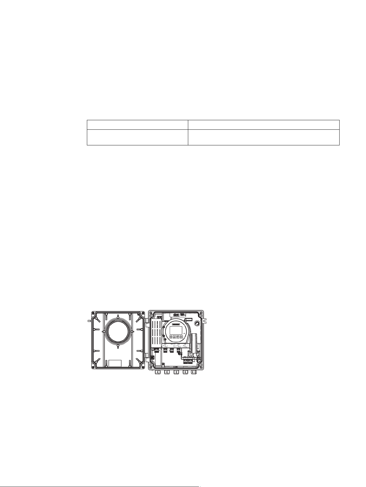
Transmitter
Wall mount enclosure with internal DSL
3.2
Features
SITRANS F US ultrasonic flow meter systems consist of a transmitter and a sensor. The
following table lists the available combinations of transmitters and sensors.
FST030 FSS200
The transmitter reads the measured process values from the sensor and calculates derived
values. It provides up to five configurable I/Os, HART communication, USB service channel,
and a local display. It also adds functionalities such as totalizers, access control, diagnostics,
and configuration. The local user interface consists of a display and four buttons for user
interaction.
The transmitter has a modular design with discrete, replaceable electronic modules and
connection boards to maintain separation between functions and facilitate field service. All
modules are fully traceable and their provenance is included in the transmitter setup.
The SITRANS FST030 is available as:
SITRANS F Ultrasonic flowmeters FST030 (HART)
Operating Instructions, 08/2017, A5E35971532-AC
● The flowmeter can be used as HART slave in operation on SIEMENS SIMATIC S7/PCS7
or third party automation systems
● Available as wall mount enclosure
21

Description
3.2 Features
● Full graphical local display
● SensorFlash (SD card) for memory backup and documentation storage (certificates etc.)
● USB service interface
● One current output
– Channel 1: Current output with HART
● Up to five input/output channels:
– Channel 2: Signal output; can be parameterized for:
Current output (0/4 to 20 mA)
Pulse output
Frequency output
Alarm, status
– Channels 3 and 4: Signal output
Current output (0/4 to 20 mA)
Pulse output
Frequency output
Alarm, status
Pulse or frequency redundancy mode (only channel 3)
– Channels 3 and 4: Relay output; can be parameterized as:
Alarm, status
– Channels 3 and 4: Signal input; can be parameterized as:
Current input (4 to 20 mA)
Totalizer control (resetting of totalizers)
Zero adjustment
Freezing of process values
Forcing of outputs
– Channels 5 and 6:
Temperature input (RTD)
● Current, frequency, and pulse outputs with configurable fail safe mode
● HART communication interface (HART 7.5)
● High immunity against process noise
● Fast response to step changes in flow
● High update rate (100 Hz) on all process values
SITRANS F Ultrasonic flowmeters FST030 (HART)
22 Operating Instructions, 08/2017, A5E35971532-AC

Description
3.2 Features
● Measurement of:
– Volume flow
– Mass flow
– Flow velocity
– Sound velocity
– LiquIdent (hydrocarbon variant only)
– Liquid identifier (hydrocarbon variant only)
– Medium temperature
– Standard density
– Standard kinematic viscosity
– API gravity (hydrocarbon variant only)
– Standard API gravity (hydrocarbon variant only)
– Specific gravity (hydrocarbon variant only)
– Standard specific gravity (hydrocarbon variant only)
● Measurement with external equipment connected to the transmitter via input channels 3
and 4
– Medium temperature
– Pressure
– Kinematic viscosity
– Density
● Configurable upper and lower alarms and warning limits for nearly all process values
● Independent low flow cut-off settings for volume flow and mass flow
● Zero-point adjustment (initiated by host system)
● Process noise damping using digital signal processing (DSP)
● Three totalizers for summation of flow process values
● Simulation of process values
● Simulation of all outputs
● Simulation of alarms
● Enabling alarms for visibility on all outputs (HMI, status and communication)
● Comprehensive diagnostics (NAMUR or Siemens standard) for troubleshooting and
sensor checking
● Firmware update
● Use in hazardous areas according to specification
● USB mass storage* (not available in the USA)
● Data logging in SensorFlash
SITRANS F Ultrasonic flowmeters FST030 (HART)
Operating Instructions, 08/2017, A5E35971532-AC
23

Description
3.3
Applications
3.4
Approvals
Note
For further details see
3.3 Applications
● Peak indicators
● Alarm delay
* The SD-Card Mass storage function is not available for use in the USA. This option is not
available for ordering or shall not be ordered where end user may be located within USA.
● Water industry
● Wastewater industry
● HVAC industry
● Petrochemical industry
● Irrigation systems
● Plants transporting non-conductive liquids
● Power industry
● Processing industry
Approvals (Page 119).
The device is available with approvals for general purpose and for hazardous areas. In all
cases, check the nameplate on your device, and confirm the approval rating.
SITRANS F Ultrasonic flowmeters FST030 (HART)
24 Operating Instructions, 08/2017, A5E35971532-AC
Description
3.5
HART communication
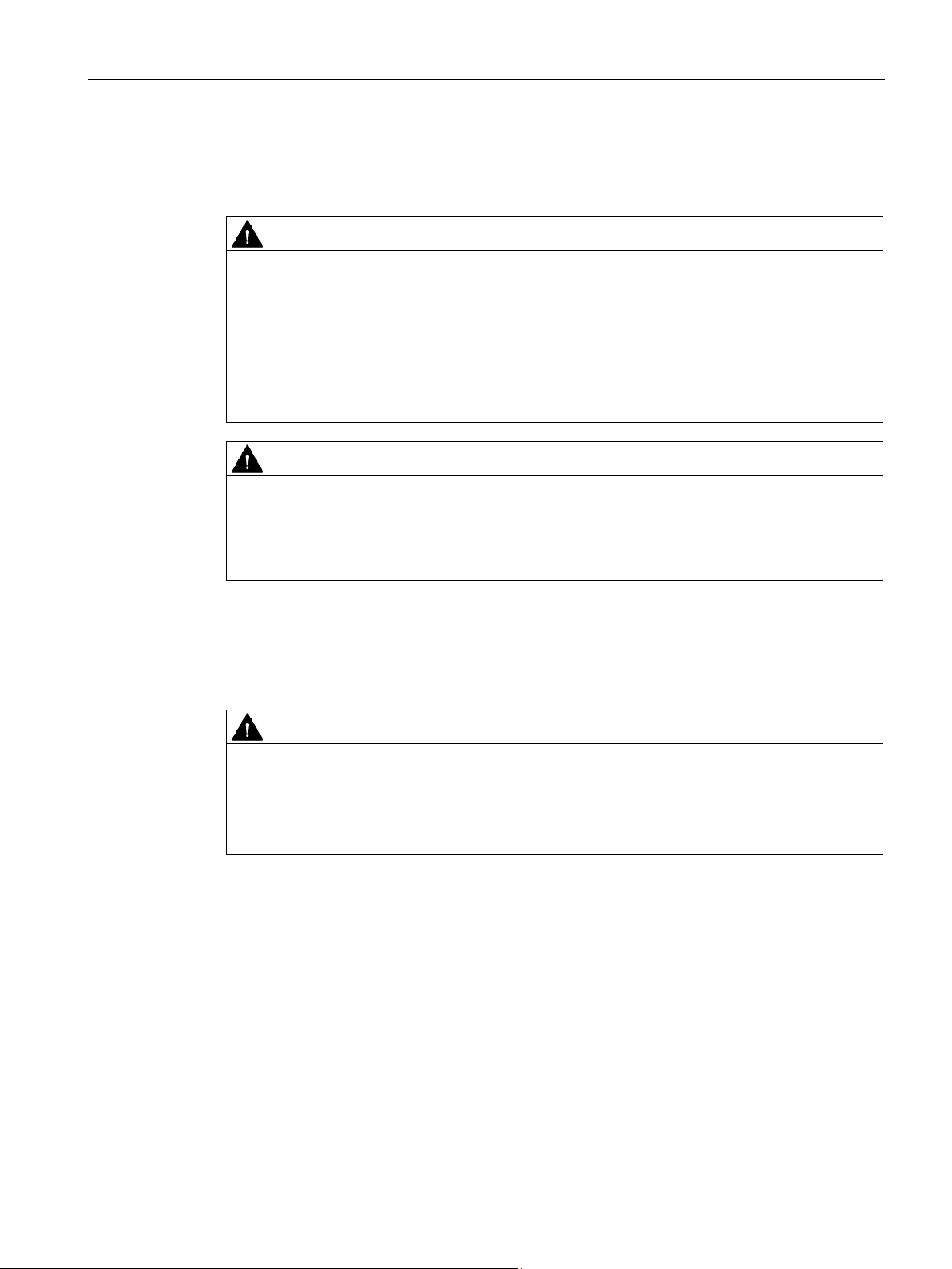
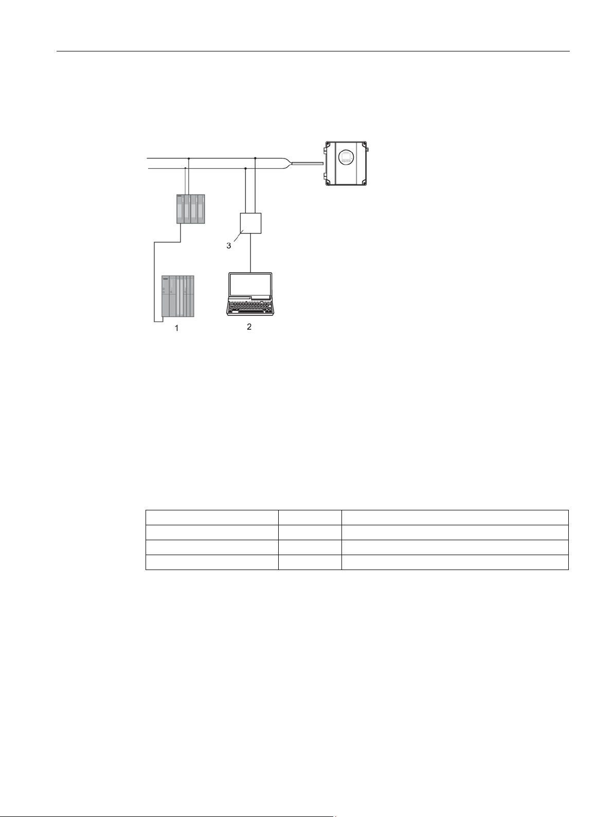
①
SIMATIC PLC system with HART interface
②
PC with SIMATIC PDM or similar application
③
HART modem
System communication
Manufacturer ID
42 (2A Hex)
Manufacturer ID parameter
Device type
34 (22 Hex)
Device type parameter
HART protocol revision
7.5
HART protocol revision parameter
Device revision
2
Device revision parameter
Device description files
3.5 HART communication
Communication is via the HART protocol, using:
Figure 3-1 System integration example
The flowmeter can be used in a number of system configurations to enable simple, secure,
and reliable data transmission over long distances.
Table 3- 1 HART protocol identification data
Note: Version numbers and other references shown above are typical or example values.
Available EDD drivers:
● SIMATIC PDM
● FDT/DTM
● AMS suite
● 375 Field Communicator
The drivers can be downloaded here:
SITRANS F Ultrasonic flowmeters FST030 (HART)
Operating Instructions, 08/2017, A5E35971532-AC
25

Description
Configuration of the HART polling address
DIP switch configuration
Address
Switch 1
Switch 2
Switch 3
Switch 4
0 0 0 0 0
1 1 0 0 0
2 0 1 0 0 3 1 1 0
0
4 0 0 1 0
5 1 0 1 0
6 0 1 1 0 7 1 1 1
0
9 1 0 0 1
11 1 1 0 1
12 0 0 1 1
13 1 0 1 1
14 0 1 1 1
15 1 1 1 1
0: OFF; 1: ON
3.5 HART communication
Download EDD files (http://www.siemens.com/flowdocumentation)
The HART address can be set either via hardware (DIP switch) or via software (local display
or SIMATIC PDM).
The DIP switch is located on the transmitter cassette.
Figure 3-2 HART slave address switch
● Configuration via DIP switch (HW polling address)
Set 1 to 15 on the DIP switch if you wish to set a fixed (hardware-defined) HART polling
address (SW polling address will be ignored). The configured HW polling address can be
read via HMI in menu item 4.2.
● Configuration via the local display or SIMATIC PDM (SW polling address)
Disable the HW polling address by setting all switches to "OFF" on the HART DIP switch.
The device starts up with default slave address = 0. The SW polling address can be
changed to a value between 0 and 63 via HMI (menu item 4.1) or SIMATIC PDM
Table 3- 2 HW polling address
8 0 0 0 1
10 0 1 0 1
SITRANS F Ultrasonic flowmeters FST030 (HART)
26 Operating Instructions, 08/2017, A5E35971532-AC

Description
Mapping of measured process variables
The following table shows the possible and default mappings.
Device
Variable
Number
Device Variable Name
SV TV QV
0
Volume flow
D X X
X
2
Sound Velocity
X X D
X
4
Process Density
X X X
X
5
Process Temperature
X X X X 6
Process Pressure
X X X
X
7
Process Viscosity
X X X
X
8
Temperature 1
X X X X 9
Temperature 2
X X X
X
10
Concentration
X X X
X
11
Current in (Channel 5)
X X X
X
12
Current in (Channel 6)
X X X X 13
Standard Volume Flow
X X X
X
14
Standardizing Factor
X X X
X
15
Standard Viscosity
X X X
X
16
Standard Density
X X X X 17
LiquIdent
X X X
X
18
API Gravity
X X X
X
19
Standard API Gravity
X X X
X
21
Standard Specific Gravity
X X X
X
22
Rate of Change
X X X
X
23
Energy Flow
X X X
X
24
Delta Temperature
X X X X 25
Energy Efficiency Rating
X X X
X
27
Totalized Value 1
X X X 28
Totalized Value 2
X X
X
29
Totalized Value 3
X X
X
3.5 HART communication
The device supports all four dynamic variables (PV, SV, TV and QV). Except for PV, they
can be freely mapped to all device variables.
PV
1 Mass flow X D X X
3 Flow Velocity X X X D
SITRANS F Ultrasonic flowmeters FST030 (HART)
Operating Instructions, 08/2017, A5E35971532-AC
20 Specific Gravity X X X X
26 Coefficient of Performance X X X X
"D" marking denotes default mapping.
27

Description
3.5.1
Universal commands
Command number
Function
0
Read Unique Identifier
2
Read Loop Current And Percent Of Range
3
Read Dynamic Variables And Loop Current
6
Write Polling Address
7
Read Loop Configuration
8
Read Dynamic Variable Classifications
9
Read Device Variables With Status
11
Read Unique Identifier Associated With Tag
12
Read Message
13
Read Tag, Descriptor, Date
14
Read Primary Variable Transducer Information
15
Read Device Information
16
Read Final Assembly Number
17
Write Message
18
Write Tag, Descriptor, Date
19
Write Final Assembly Number
20
Read Long Tag
21
Read Unique Identifier Associated With Long Tag
22
Write Long Tag
48
Read Additional Device Status
3.5 HART communication
The device supports the following universal commands:
Table 3- 3 Universal commands
1 Read Primary Variable
38 Reset Configuration Changed Flag
SITRANS F Ultrasonic flowmeters FST030 (HART)
28 Operating Instructions, 08/2017, A5E35971532-AC
 Loading...