

Siemens SITRANS F,FST020 IP65 NEMA 4X Operating Instructions Manual

SITRANS F
Ultrasonic Flowmeters
FST020 IP65 NEMA 4X
Introduction
1
Operating Instructions
Safety notes
Description
Installing/mounting
Connecting
Commissioning
Operating
Service and maintenance
Diagnosing and
troubleshooting
2
3
4
5
6
7
8
9
Technical data
Dimension drawings
Replacement parts
Modbus communication
Certificates and support
SIMATIC PDM
10
11
12
A
B
C
09/2017
A5E41425845-AB
Legal information
Warning notice system
This manual contains notices you have to observe in order to ensure your personal safety, as well as to prevent
damage to property. The notices referring to your personal safety are highlighted in the manual by a safety alert
symbol, notices referring only to property damage have no safety alert symbol. These notices shown below are
graded according to the degree of danger.
DANGER
indicates that death or severe personal injury will result if proper precautions are not taken.
WARNING
indicates that death or severe personal injury may result if proper precautions are not taken.
CAUTION
indicates that minor personal injury can result if proper precautions are not taken.
NOTICE
indicates that property damage can result if proper precautions are not taken.
If more than one degree of danger is present, the warning notice representing the highest degree of danger will be
used. A notice warning of injury to persons with a safety alert symbol may also include a warning relating to property
damage.
Qualified Personnel
The product/system described in this documentation may be operated only by personnel qualified for the specific
task in accordance with the relevant documentation, in particular its warning notices and safety instructions. Qualified
personnel are those who, based on their training and experience, are capable of identifying risks and avoiding
potential hazards when working with these products/systems.
Proper use of Siemens products
Note the following:
WARNING
Siemens products may only be used for the applications described in the catalog and in the relevant technical
documentation. If products and components from other manufacturers are used, these must be recommended or
approved by Siemens. Proper transport, storage, installation, assembly, commissioning, operation and
maintenance are required to ensure that the products operate safely and without any problems. The permissible
ambient conditions must be complied with. The information in the relevant documentation must be observed.
Trademarks
All names identified by ® are registered trademarks of Siemens AG. The remaining trademarks in this publication
may be trademarks whose use by third parties for their own purposes could violate the rights of the owner.
Disclaimer of Liability
We have reviewed the contents of this publication to ensure consistency with the hardware and software described.
Since variance cannot be precluded entirely, we cannot guarantee full consistency. However, the information in
this publication is reviewed regularly and any necessary corrections are included in subsequent editions.
Siemens AG
Division Process Industries and Drives
Postfach 48 48
90026 NÜRNBERG
GERMANY
Document order number: A5E41425845
Ⓟ 10/2017 Subject to change
Copyright © Siemens AG 2017.
All rights reserved

Table of contents
1 Introduction...................................................................................................................................................9
1.1 Purpose of this documentation.................................................................................................9
1.2 Product compatibility................................................................................................................9
1.3 Document history.....................................................................................................................9
1.4 Device documentation package.............................................................................................10
1.5 Items supplied........................................................................................................................10
1.6 Checking the consignment.....................................................................................................11
1.7 Further Information.................................................................................................................11
1.8 Notes on warranty..................................................................................................................12
2 Safety notes................................................................................................................................................13
2.1 Precondition for use...............................................................................................................13
2.2 Warning symbols on the device.............................................................................................13
2.3 Laws and directives................................................................................................................13
2.4 Conformity with European directives......................................................................................14
2.5 Lithium batteries.....................................................................................................................14
3 Description..................................................................................................................................................15
3.1 Overview................................................................................................................................15
3.2 Design....................................................................................................................................15
3.3 Features.................................................................................................................................16
4 Installing/mounting......................................................................................................................................19
4.1 Chapter overview (transmitter)...............................................................................................19
4.2 Installation location requirements...........................................................................................19
4.2.1 Environment...........................................................................................................................19
4.2.2 Normal environmental conditions...........................................................................................20
4.3 Installation instructions...........................................................................................................20
4.3.1 Wall mount transmitter...........................................................................................................20
5 Connecting.................................................................................................................................................25
5.1 Basic safety notes..................................................................................................................25
5.1.1 Missing PE/ground connection...............................................................................................25
5.1.2 Energized devices..................................................................................................................25
5.2 Disconnecting device.............................................................................................................26
5.3 Device nameplates.................................................................................................................26
5.3.1 Device nameplate..................................................................................................................27
FST020 IP65 NEMA 4X
Operating Instructions, 09/2017, A5E41425845-AB 3

Table of contents
5.4 Transmitter power supply, communications and I/O connections..........................................28
5.4.1 Sensor connections................................................................................................................28
5.4.2 Connecting the power supply.................................................................................................28
5.4.3 Connecting Inputs/Outputs.....................................................................................................30
5.4.4 Connection Wiring..................................................................................................................31
5.4.5 Finishing the transmitter connection (wall mount housing)....................................................33
6 Commissioning...........................................................................................................................................35
6.1 Basic Safety notes.................................................................................................................35
6.1.1 Hazardous contact voltage.....................................................................................................35
6.2 General requirements............................................................................................................36
6.3 Power-up................................................................................................................................36
6.4 Local display..........................................................................................................................36
6.5 Initial startup...........................................................................................................................36
6.6 Commissioning via local display............................................................................................37
6.6.1 Chapter overview...................................................................................................................37
6.6.2 Wizards..................................................................................................................................38
6.6.2.1 Quick Commissioning wizard (menu item 1.1).......................................................................38
6.6.2.2 Quick Commissioning wizard (wizard)...................................................................................38
6.6.2.3 Sensor settings wizard (menu item 1.2).................................................................................38
6.6.2.4 Sensor settings wizard (wizard).............................................................................................39
6.6.2.5 Process Values wizard (menu item 1.3).................................................................................43
6.6.2.6 Process values wizard (wizard)..............................................................................................44
6.6.2.7 Inputs/Outputs wizard............................................................................................................45
6.6.3 Navigating the menu structure...............................................................................................45
6.6.3.1 Chapter overview...................................................................................................................45
6.6.3.2 Navigation view......................................................................................................................45
6.6.3.3 Navigating the menu structure...............................................................................................46
7 Operating....................................................................................................................................................47
7.1 Display views.........................................................................................................................47
7.2 Access control........................................................................................................................47
7.3 Operating the FST020............................................................................................................48
7.3.1 Fixed display texts..................................................................................................................48
7.3.2 Reading the process values...................................................................................................49
7.3.3 Operating the totalizer............................................................................................................51
7.3.4 Handling alarms.....................................................................................................................52
7.3.5 Reading the diagnostic values...............................................................................................53
7.3.6 Reading / changing parameters.............................................................................................53
7.3.6.1 Parameter view introduction...................................................................................................53
7.3.7 Alphanumeric parameters......................................................................................................53
7.3.7.1 Changing the resolution.........................................................................................................55
8 Service and maintenance...........................................................................................................................57
8.1 Basic safety notes..................................................................................................................57
8.1.1 Impermissible repair of the device.........................................................................................57
8.2 Recalibration..........................................................................................................................57
FST020 IP65 NEMA 4X
4 Operating Instructions, 09/2017, A5E41425845-AB

Table of contents
8.3 Maintenance and repair work.................................................................................................57
8.3.1 Maintenance...........................................................................................................................57
8.3.2 Service and maintenance information....................................................................................58
8.4 Return procedure...................................................................................................................59
8.5 Disposal.................................................................................................................................59
9 Diagnosing and troubleshooting.................................................................................................................61
9.1 Introduction............................................................................................................................61
9.2 Device status icons................................................................................................................61
9.3 Fault codes and corrective actions.........................................................................................62
9.3.1 Alarm messages....................................................................................................................62
10 Technical data............................................................................................................................................65
10.1 Power.....................................................................................................................................65
10.2 Inputs.....................................................................................................................................65
10.3 Outputs...................................................................................................................................66
10.4 Construction...........................................................................................................................66
10.5 Operating conditions..............................................................................................................67
10.6 Approvals...............................................................................................................................68
10.7 SensorFlash...........................................................................................................................68
11 Dimension drawings...................................................................................................................................69
11.1 Dimension drawing.................................................................................................................69
12 Replacement parts.....................................................................................................................................71
12.1 AC Transmitter exploded view...............................................................................................71
A Modbus communication..............................................................................................................................73
A.1 Modbus addressing model.....................................................................................................73
A.2 Modbus communication.........................................................................................................73
A.3 Coil configuration...................................................................................................................75
A.4 Modbus register mapping.......................................................................................................76
A.5 Integer byte order...................................................................................................................78
A.6 Float byte order......................................................................................................................78
A.7 Modbus function codes..........................................................................................................78
A.8 Access control........................................................................................................................80
A.9 Modbus holding register tables..............................................................................................80
A.9.1 Modbus holding registers tables............................................................................................80
A.9.2 Process values.......................................................................................................................81
A.9.3 Totalizers................................................................................................................................82
A.9.4 Units.......................................................................................................................................84
A.9.5 Device reset...........................................................................................................................89
A.9.6 Setup......................................................................................................................................90
FST020 IP65 NEMA 4X
Operating Instructions, 09/2017, A5E41425845-AB 5

Table of contents
A.9.6.1 Sensor....................................................................................................................................90
A.9.6.2 Process values.....................................................................................................................108
A.9.6.3 Totalizers..............................................................................................................................112
A.9.6.4 Inputs and outputs................................................................................................................113
A.9.6.5 Date and time.......................................................................................................................126
A.9.6.6 Local display........................................................................................................................127
A.9.6.7 Selectable values dependent on the view type....................................................................137
A.9.6.8 Process value filter masks...................................................................................................138
A.9.7 Maintenance and diagnostics...............................................................................................139
A.9.7.1 Identification.........................................................................................................................139
A.9.8 Diagnostic events.................................................................................................................141
A.9.8.1 Active events........................................................................................................................141
A.9.8.2 Diagnostic log.......................................................................................................................145
A.9.8.3 Alarm items..........................................................................................................................146
A.9.9 Diagnostics...........................................................................................................................150
A.9.9.1 Sensor..................................................................................................................................150
A.9.9.2 DSL......................................................................................................................................151
A.9.9.3 Temperature monitoring.......................................................................................................152
A.9.9.4 Inputs and outputs................................................................................................................153
A.9.9.5 Peak values..........................................................................................................................155
A.9.10 Characteristics.....................................................................................................................159
A.9.10.1 Transmitter...........................................................................................................................159
A.9.10.2 Sensor frontend....................................................................................................................159
A.9.11 SensorFlash.........................................................................................................................160
A.9.11.1 SensorFlash.........................................................................................................................160
A.9.11.2 Data logging.........................................................................................................................161
A.9.12 Simulation............................................................................................................................162
A.9.12.1 Inputs and outputs................................................................................................................162
A.9.12.2 Process values.....................................................................................................................164
A.9.12.3 Alarms..................................................................................................................................165
A.9.13 Audit trail..............................................................................................................................167
A.9.13.1 Operating time......................................................................................................................167
A.9.13.2 Parameter change log..........................................................................................................167
A.9.13.3 FW update change log.........................................................................................................169
A.9.14 Communication....................................................................................................................170
A.9.14.1 Service channel....................................................................................................................170
A.9.15 Security................................................................................................................................170
A.9.15.1 Access management............................................................................................................170
B Certificates and support............................................................................................................................173
B.1 Certificates...........................................................................................................................173
B.2 Technical support.................................................................................................................173
B.3 QR code label......................................................................................................................174
C SIMATIC PDM..........................................................................................................................................175
C.1 Commissioning with PDM....................................................................................................175
C.1.1 Introduction..........................................................................................................................175
C.1.2 Functions in SIMATIC PDM.................................................................................................175
C.1.3 Supported SIMATIC PDM versions......................................................................................175
C.1.4 Initial setup...........................................................................................................................176
C.1.5 Integrating the EDD..............................................................................................................176
FST020 IP65 NEMA 4X
6 Operating Instructions, 09/2017, A5E41425845-AB

Table of contents
C.1.6 Adding device to communication network............................................................................178
C.1.7 Configuring a new device.....................................................................................................179
C.1.8 Wizard - Quick Start via PDM..............................................................................................180
C.1.9 Wizard - Clamp-On Configuration........................................................................................181
C.1.10 Wizard - Zero point adjustment............................................................................................181
C.1.11 Changing parameter settings using SIMATIC PDM.............................................................182
C.1.12 Parameters accessed via drop-down menus.......................................................................183
C.1.13 Process variables.................................................................................................................184
Index.........................................................................................................................................................187
FST020 IP65 NEMA 4X
Operating Instructions, 09/2017, A5E41425845-AB 7

Table of contents
FST020 IP65 NEMA 4X
8 Operating Instructions, 09/2017, A5E41425845-AB

Introduction
1.1 Purpose of this documentation
These instructions contain all information required to commission and use the device. Read
the instructions carefully prior to installation and commissioning. In order to use the device
correctly, first review its principle of operation.
The instructions are aimed at persons mechanically installing the device, connecting it
electronically, configuring the parameters and commissioning it, as well as service and
maintenance engineers.
1.2 Product compatibility
Edition Remarks Device revision Compatible device revision integration package
09/2017 First edition Modbus
FW: 2.01.00-04
HW: 002 or later
SIMATIC PDM V8.2 SP1 or
later
AMS Device Manager 12.0 EDD: 1.00.00 or later
SITRANS DTM V4.1 EDD: 1.00.00 or later
Field communicator V3.8 EDD: 1.00.00 or later
EDD: 1.00.00 or later
1
1.3 Document history
The following table shows the most important changes in the documentation compared to each
previous edition.
Edition Note
09/2017 First edition
FST020 IP65 NEMA 4X
Operating Instructions, 09/2017, A5E41425845-AB 9
Introduction
1.5 Items supplied
1.4 Device documentation package
The user documentation package for this product includes the following documents:
Document Purpose Intended users Availability
Operating Instruc‐
tions
Contains all information needed to
● check and identify the delivered
package
● install and electrically connect the
product
● commission the product, (setting
parameters via HMI menu)
● operate and maintain the device on a
daily basis
● troubleshoot and remedy minor
operation interruptions
Instrument techni‐
cians, plant opera‐
tors
● Available for download from
homepage
● Hardcopy can be purchased
via PIA Life Cycle Portal
(only English and German
versions)
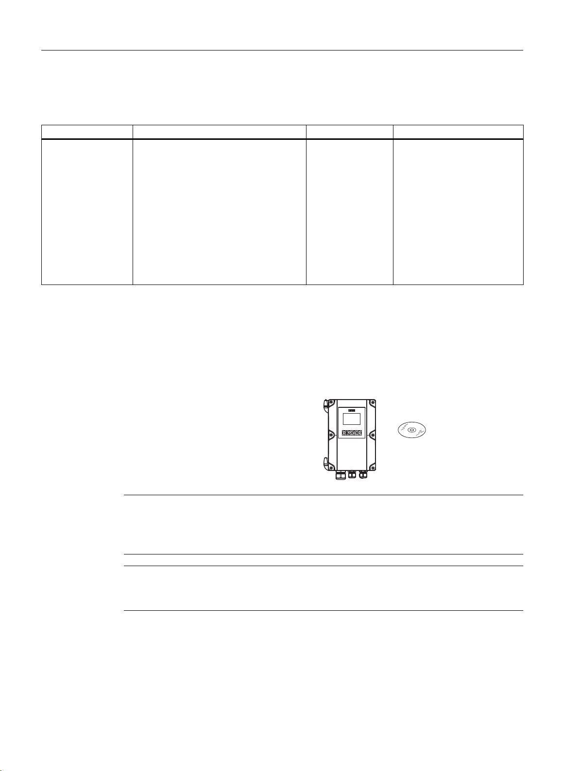
1.5 Items supplied
The device is delivered as:
Wall mount enclosure
● FST020 transmitter wall mount enclosure
● Siemens Process Instrumentation disk
containing certificates and manuals.
Note
Supplementary information
Supplementary product and production specific certificates are included on the SensorFlash®
SD card in the transmitter socket.
Note
Scope of delivery may vary, depending on version and add-ons. Make sure the scope of
delivery and the information on the nameplate correspond to your order and the delivery note.
FST020 IP65 NEMA 4X
10 Operating Instructions, 09/2017, A5E41425845-AB

1.6 Checking the consignment
Check the device packaging for damage. Inform your supplier of any damage. Retain the
damaged parts for clarification.
Check the scope of delivery by comparing the shipping documents with your order for
correctness and completeness.
Do not take damaged or incomplete devices into operation under any circumstances.
Special conditions for storage and transportation of device listed in Section "Service and
maintenance (Page 57)".
Identification
Note
IMPORTANT
This device is NOT to be used in hazardous areas.
CE declaration is delivered with the device.
Introduction
1.7 Further Information
Transmitter model number is: FST020
The system ordering code represents the transmitter including accessories.
AC System ordering code: 7ME3570-1JA4XXXXXX
DC System ordering code: 7ME3570-1JB4XXXXXX
AC - Transmitter ordering code: 7ME3570 - 1JA40-0AA1
DC - Transmitter ordering code: 7ME3570 - 1JB40-0AA1
1.7 Further Information
Product information on the Internet
The Operating Instructions are available on the documentation disk shipped with the device,
and on the Internet on the Siemens homepage, where further information on the range of
SITRANS F flowmeters may also be found:
Product information on the internet (
Worldwide contact person
http://www.siemens.com/flow)
If you need more information or have particular problems not covered sufficiently by these
Operating Instructions, get in touch with your contact person. You can find contact information
for your local contact person on the Internet:
Local contact person (http://www.automation.siemens.com/partner)
FST020 IP65 NEMA 4X
Operating Instructions, 09/2017, A5E41425845-AB 11

Introduction
1.8 Notes on warranty
See also
Technical support (Page 173)
1.8 Notes on warranty
The contents of this manual shall not become part of or modify any prior or existing agreement,
commitment or legal relationship. The sales contract contains all obligations on the part of
Siemens as well as the complete and solely applicable warranty conditions. Any statements
regarding device versions described in the manual do not create new warranties or modify the
existing warranty.
The content reflects the technical status at the time of publishing. Siemens reserves the right
to make technical changes in the course of further development.
FST020 IP65 NEMA 4X
12 Operating Instructions, 09/2017, A5E41425845-AB

Safety notes
2.1 Precondition for use
This device left the factory in good working condition. In order to maintain this status and to
ensure safe operation of the device, observe these instructions and all the specifications
relevant to safety.
Observe the information and symbols on the device. Do not remove any information or symbols
from the device. Always keep the information and symbols in a completely legible state.
2.2 Warning symbols on the device
Symbol Explanation
Caution. The Caution symbol is used throughout the operating instructions.
2
2.3 Laws and directives
Observe the safety rules, provisions and laws applicable in your country during connection,
assembly and operation. These include, for example:
● National Electrical Code (NEC - NFPA 70) (USA)
● Canadian Electrical Code (CEC) (Canada)
For CE marked equipment the device complies with the following directives:
● Low voltage directive LVD 2014/35/EU
● EMC directive 2014/35/EU
● Restriction of hazardous substances directive 2011/65/EC and 2015/863/EU
FST020 IP65 NEMA 4X
Operating Instructions, 09/2017, A5E41425845-AB 13

Safety notes
2.5 Lithium batteries
2.4 Conformity with European directives
The CE marking on the device symbolizes the conformity with the following European
directives:
Electromagnetic compatibili‐
ty EMC
2014/30/EU
Low voltage directive LVD
2014/35/EU
Restrictions on Hazardous
Substances
RoHS 2011/65/EC and
2015/863/EU
The applicable directives can be found in the EU declaration of conformity of the specific device.
2.5 Lithium batteries
Lithium batteries are primary power sources with high energy content designed to represent
the highest possible degree of safety.
WARNING
Lithium batteries
Explosion Hazard - Can cause death or serious injury.
Directive of the European Parliament and of the Council on the
harmonisation of the laws of the Member States relating to elec‐
tromagnetic compatibility
Directive of the European Parliament and of the Council on the
harmonisation of the laws of the Member States relating to the
making available on the market of electrical equipment designed
for use within certain voltage limits
EU Directive: Restriction of Hazardous Substances in Electrical
and Electronic Equipment Directive and Annex II Commission
Delegated Directive
Lithium batteries may present an Explosion Hazard if they are abused electrically or
mechanically. This is in most circumstances associated with the generation of excessive heat
where internal pressure may cause the cell to rupture.
Thus the following basic precautions should be observed when handling and using lithium
batteries:
● Do not short-circuit, recharge or connect with false polarity.
● Do not expose to temperature beyond the specified temperature range or incinerate the
battery.
● Do not crush, puncture or open cells or disassemble battery packs.
● Do not weld or solder to the battery’s body.
● Do not expose contents to water.
FST020 IP65 NEMA 4X
14 Operating Instructions, 09/2017, A5E41425845-AB
Description
'&32:(5
3.1 Overview
SITRANS FST020 ultrasonic flow meter systems consist of a transmitter and a sensor. The
following table lists the available combinations of transmitters and sensors.
Transmitter Sensor type
FST020 FSS200 family
3.2 Design
The transmitter reads the measured process values from the sensor and calculates derived
values. It provides Modbus communications, 1x 4-20ma, 1x relay, and 1x Pulse/Frequency,
USB service port, and a local display. It also adds functionalities such as totalizers, access
control, diagnostics, and configuration. The local user interface consists of a display and four
buttons for user interaction.
The transmitter has a modular design with discrete, replaceable electronic modules and
connection boards to maintain separation between functions and facilitate field service. All
modules are fully traceable and their provenance is included in the transmitter setup.
3
DN 15 to DN 10m (0.5" to 360")
The SITRANS FST020 is available as:
Wall mount housings: AC and DC
Figure 3-1 DC Wall Mount housing shown
FST020 IP65 NEMA 4X
Operating Instructions, 09/2017, A5E41425845-AB 15
Description
3.3 Features
Pipe mount kit
The Pipe kit is CQO:1012NMB-1.
Figure 3-2 Pipe Mounting shown with mounting plate
3.3 Features
● Wall mount IP65 enclosure
● Full graphical local display
● SensorFlash (SD card) for memory backup, Datalogger and documentation storage
(certificates etc.)
● USB service interface
● Modbus communications
● One pulse/frequency output
● One relay
● One current output 4-20 mA
● High immunity against process noise
● Fast response to step changes in flow
● High update rate (100 Hz) on all process values
FST020 IP65 NEMA 4X
16 Operating Instructions, 09/2017, A5E41425845-AB

Description
3.3 Features
● Measurement of:
– Volume flow
– Mass flow (with fixed density setpoint)
– Flow velocity
– Sound velocity
● Configurable upper and lower alarms and warning limits for nearly all process values
● Independent low flow cut-off settings for volume flow and mass flow
● Zero-point adjustment (initiated by host system)
● Process noise damping using digital signal processing (DSP)
● Simulation of process values
● Simulation of all outputs
● Simulation of alarms
● Enabling alarms for visibility on all outputs (HMI, status and communication)
● Comprehensive diagnostics (Siemens standard) for troubleshooting and sensor checking
● Firmware update
● Data logging in SensorFlash
● Peak indicators
● Alarm delay
FST020 IP65 NEMA 4X
Operating Instructions, 09/2017, A5E41425845-AB 17

Description
3.3 Features
FST020 IP65 NEMA 4X
18 Operating Instructions, 09/2017, A5E41425845-AB
Installing/mounting
4.1 Chapter overview (transmitter)
This chapter describes how to install the wall mount housing transmitter.
Wall mount housing
The wall mount housing transmitter can be mounted either on a wall or on a pipe (with optional
pipe mount bracket), see Installation instructions (Page 20).
4.2 Installation location requirements
4.2.1 Environment
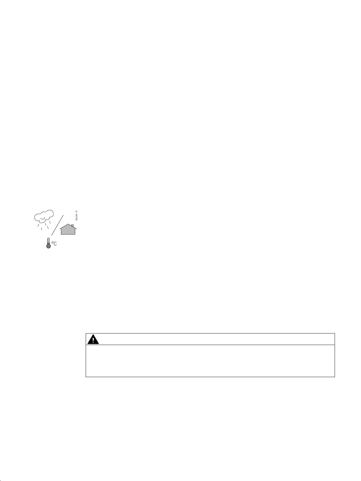
SITRANS F flowmeters with minimum IP65/NEMA 4X enclosure rating are suitable for indoor
and outdoor installations.
Process pressure and medium temperature
If applicable, make sure that specifications for rated medium temperature (TS) plus ambient
temperature that are indicated on the device nameplate / label will not be exceeded.
4
Aggressive atmospheres
Ensure that the device is suitable for the application and that it is installed where there is no
risk of penetration of aggressive vapors.
Direct sunlight
Prevent the device from overheating or materials becoming brittle due to UV exposure by
protecting it from direct sunlight. Make sure that the maximum permissible ambient
temperature is not exceeded. Refer to the information in Technical data (Page 65).
WARNING
Electrical shock hazard
May cause death or serious injury
Disconnect power before working on this product.
Upstream / Downstream
Avoid long drop lines downstream from the sensor to prevent the meter pipe from draining.
Avoid installing the sensor upstream of a free discharge in a drop line where possible.
FST020 IP65 NEMA 4X
Operating Instructions, 09/2017, A5E41425845-AB 19
Installing/mounting
4.3 Installation instructions
Sensor Location in piping system
The optimum location in the system depends on the presence of excessive gas or air bubbles
in the fluid may result in erroneous measurements. Therefore, it is preferred not to install the
sensor at the highest point in the system, where gas / air bubbles will be trapped. For liquids
it is advantageous to install the sensor in low pipeline sections, at the bottom of a U-section
in the pipeline.
4.2.2 Normal environmental conditions
Normal environmental conditions
This standard applies to equipment designed to be safe at least under the following conditions:
● Indoor and outdoor use
● Altitude up to 2000 m
● Operating temperature -10 °C to 50 °C (14 °F to 122 °F)
● Maximum relative humidity 80 % for temperatures up to 31 °C decreasing linearly to 50 %
relative humidity at 40 °C (104 °F)
● Mains supply voltage fluctuations up to ±10 % of the nominal voltage
● Transient Overvoltages up to the levels of Overvoltage Category II
● Temporary Overvoltages occurring on the Mains supply.
● Pollution Degree II
4.3 Installation instructions
4.3.1 Wall mount transmitter
Wall mounting
WARNING
Hazardous voltage
May cause death or serious injury
Disconnect power before working on this device.
The transmitter can be mounted on any wall surface including wood, metal or concrete. Use
the appropriate bolts and screws as needed for your mounting application and adhere to local
codes.
FST020 IP65 NEMA 4X
20 Operating Instructions, 09/2017, A5E41425845-AB
PP
PP
Installing/mounting
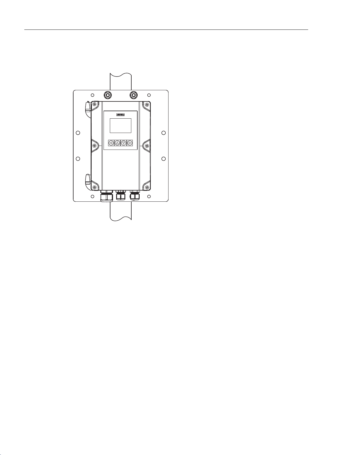
4.3 Installation instructions
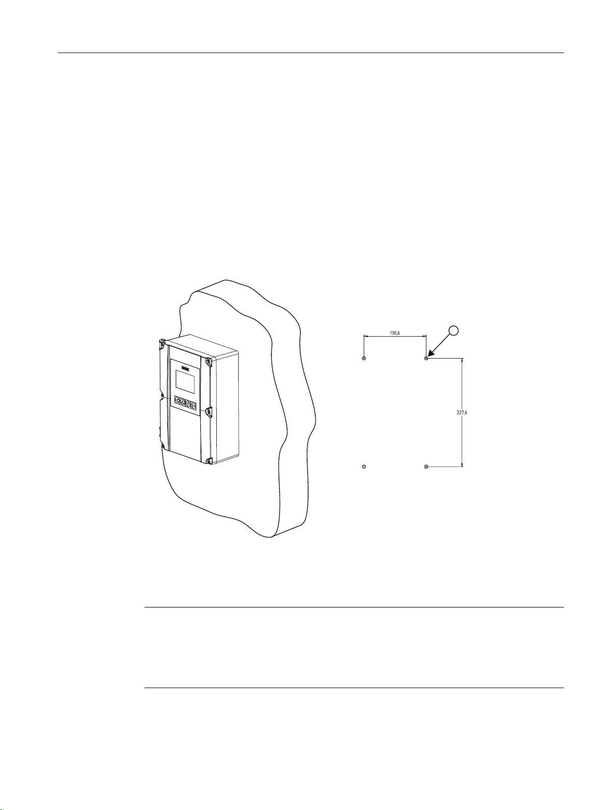
Prepare holes for the four screws (M6x100 or equivalent). Screw head diameter: max. 13.5
mm; screw shaft diameter: max. 6 mm.
● Recommended mounting: Directly to wall or to electrical cabinet back panel.
● If alternate mounting surface is used it MUST support four times the weight of the unit.
Mounting the enclosure
1. Loosen the enclosure cover screws and open the cover to reveal the mounting holes.
2. Mark and drill four holes in the mounting surface for four mounting screws (supplied).
3. Using a long flat-blade screw driver, mount transmitter and tighten screws.
4. Tighten nuts (torque: 10 Nm).
5. Refer to Connecting the power supply (Page 28) and Sensor connections (Page 28) to
complete installation.
Figure 4-1 Wall mounted transmitter showing mounting hole pattern
Mounting on pipe
Note
Mounting on pipe
For mounting on pipe, see the installation instructions given in the CQO:1012NMB-1
instructions that are provided with the optional mounting bracket kit.
U-bolts and other miscellaneous hardware are not supplied with the flowmeter.
FST020 IP65 NEMA 4X
Operating Instructions, 09/2017, A5E41425845-AB 21

Installing/mounting
4.3 Installation instructions
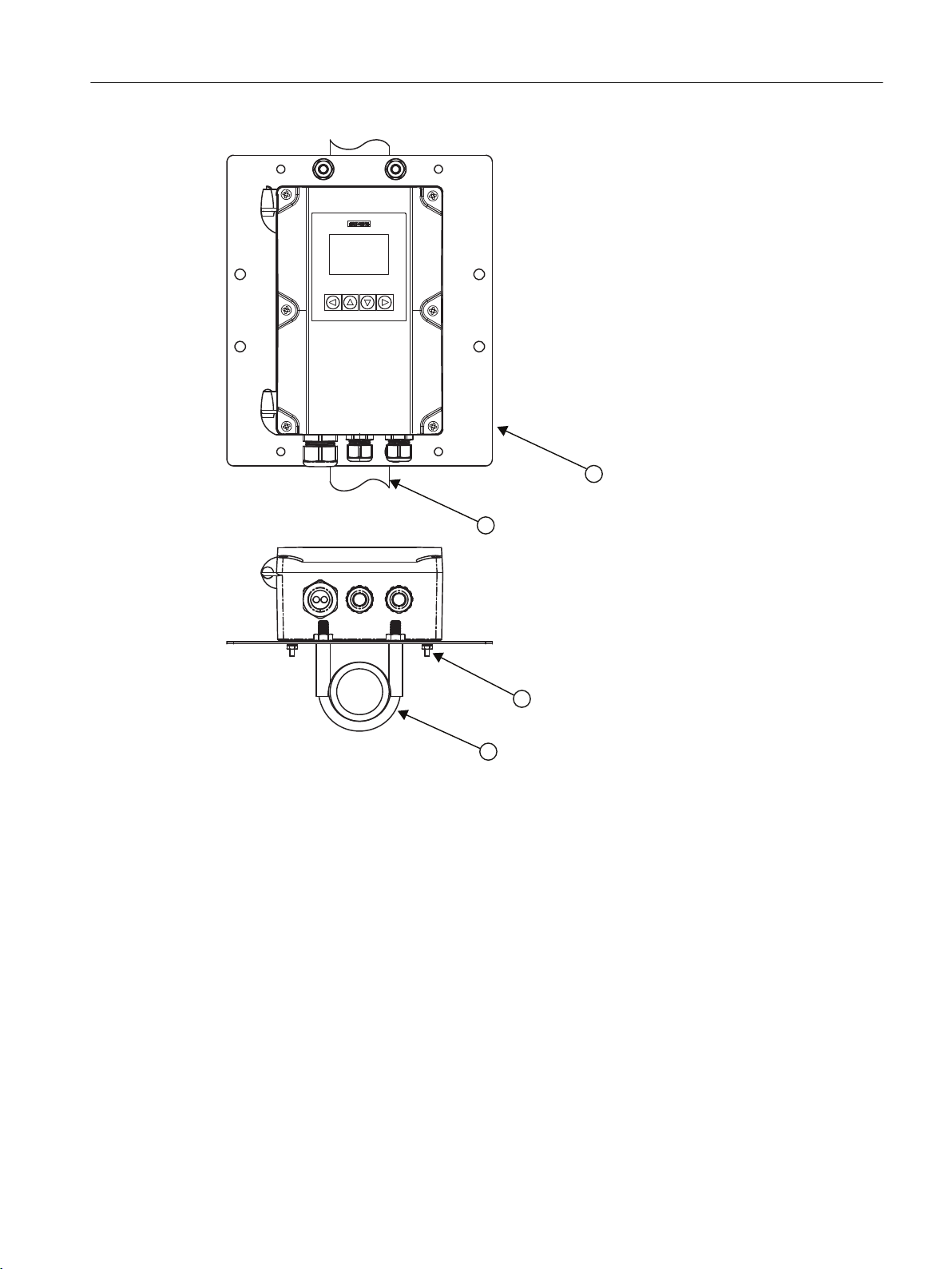
For installation on 2-inch standpipe use the optional CQO:1012NMB pipe mounting kit.
Table 4-1 CQO:1012NMB-1 Mounting Kit
Description Qty
Mounting Plate 1
U-Bolt Assembly including bracket and nuts 2
8-32 x 5/8 LG cross round head screws 4
#8 Flat washer 4
#8 Split lock washers 4
8-32 Hex nut 4
1. Affix mounting plate to standpipe using the U-bolt assemblies.
2. Secure transmitter to mounting plate using #8-32 screws, washers and nuts.
3. Tighten nuts (torque: 10 Nm).
4. Refer to Connecting the power supply (Page 28) and Sensor connections (Page 28) to
complete installation.
Note
Use conduit fittings or cable glands on all cables.
FST020 IP65 NEMA 4X
22 Operating Instructions, 09/2017, A5E41425845-AB
Installing/mounting
4.3 Installation instructions
① Mounting plate
② Stand pipe
③ Mounting hardware (see table above)
④ U-bolt assembly
FST020 IP65 NEMA 4X
Operating Instructions, 09/2017, A5E41425845-AB 23

Installing/mounting
4.3 Installation instructions
FST020 IP65 NEMA 4X
24 Operating Instructions, 09/2017, A5E41425845-AB
Connecting
This chapter describes how to wire up the transmitter for operation with a sensor.
● Transmitter power supply, communications and I/O connections (Page 28)
● Sensor connections (Page 28)
● Connecting the power supply (Page 28)
● Connecting Inputs/Outputs (Page 30)
● Connecting channel 1 (Page 31) (Modbus communication channel)
For connection of the sensor, see the relevant sensor Installation Manual.
5.1 Basic safety notes
5.1.1 Missing PE/ground connection
5
WARNING
Missing PE/ground connection
Risk of electric shock. May cause death or serious injury.
Depending on the device version, connect the power supply as follows:
● Power plug: Ensure that the used socket has a PE/ground conductor connection. Check
that the PE/ground conductor connection of the socket and power plug match each other.
● Connecting terminals: Connect the terminals according to the terminal connection
diagram. First connect the PE/ground conductor.
5.1.2 Energized devices
WARNING
Energized devices
Risk of electric shock. May cause death or serious injury.
When energized the device may be opened by qualified personnel only.
FST020 IP65 NEMA 4X
Operating Instructions, 09/2017, A5E41425845-AB 25
Connecting
5.3 Device nameplates
WARNING
Mains supply from building installation overvoltage category 2
A circuit breaker (max. 15 A) must be installed in close proximity to the equipment and within
easy reach of the operator. It must be marked as the disconnecting device for the equipment.
WARNING
DC connection devices
The DC power source must be isolated from mains supply.
5.2 Disconnecting device
Overvoltage Category II
Connect mains supply through a circuit breaker (max. 15 A) in close proximity to the transmitter
and within easy reach of the operator. Mark it as the disconnecting device for the transmitter.
5.3 Device nameplates
Each part of the system has one nameplate type showing the following information:
● product identification
● product specifications
● certificates and approvals
Note
Identification
Identify your device by comparing your ordering data with the information on the product
and specification nameplates.
The transmitter is identified as "Ultrasonic transmitter SITRANS FST020" and the sensor as
"Ultrasonic sensor SITRANS FSS200".
FST020 IP65 NEMA 4X
26 Operating Instructions, 09/2017, A5E41425845-AB
5.3.1 Device nameplate
$&'&
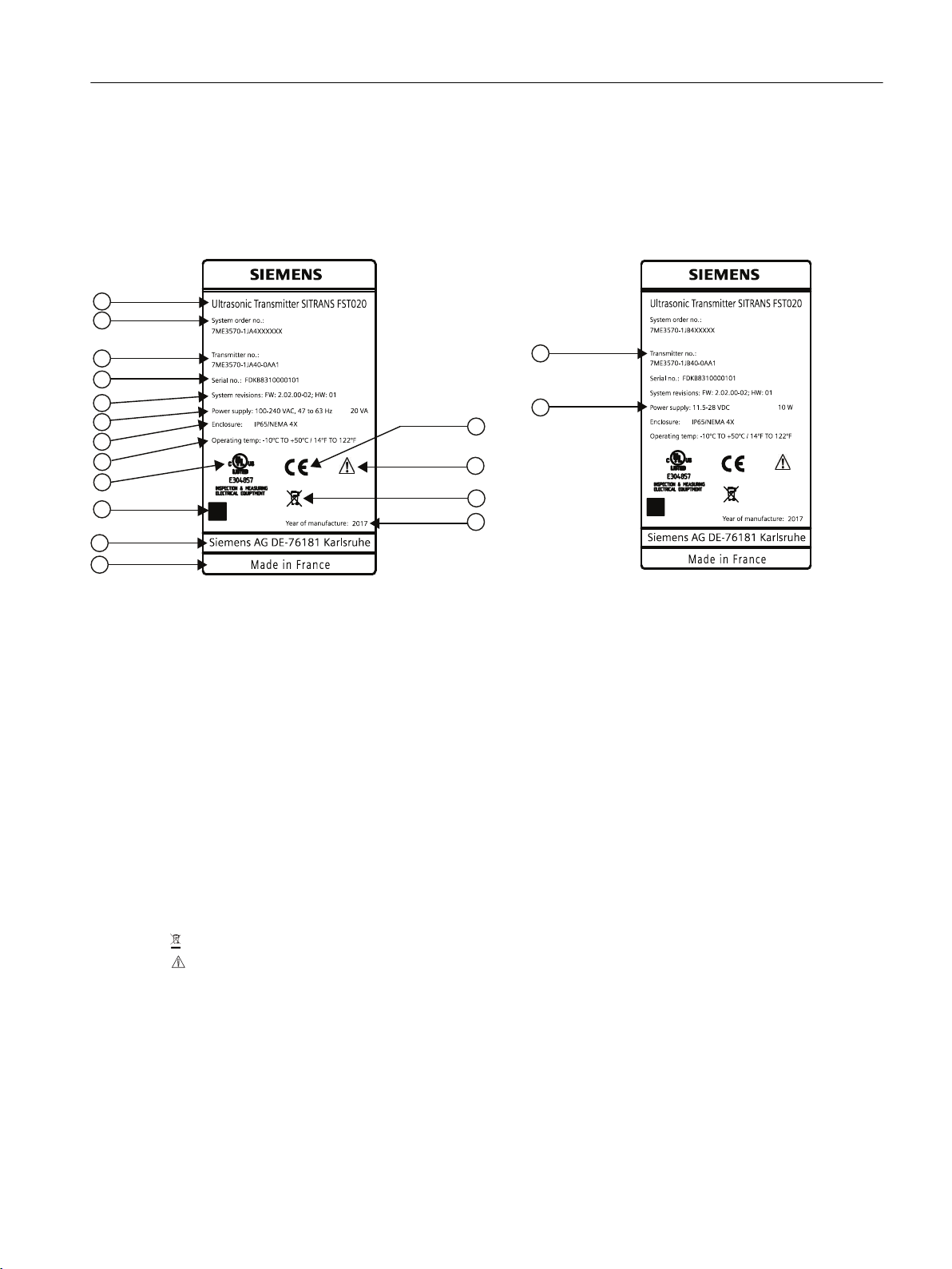
Transmitter nameplates
Connecting
5.3 Device nameplates
① Product name Transmitter product name
② System order no. Device-specific system order number (transmitter and sensor)
③ Transmitter order no. Transmitter replacement order numbers
④ Serial no. Transmitter serial number
⑤ System revisions System revision numbers; firmware (FW) and hardware (HW)
⑥ Power Supply Power supplies: AC and DC
⑦ Enclosure IP Degree of protection
⑧ Operating temperature Operating temperature of the device
⑨ Agency marking Specific agency identification marking
⑩ Data matrix code Product-specific QR-code
⑪ Contact information ad‐
dress
Contact address for device information
⑫ Place of manufacture Device place of manufacture
⑬ Year of Manufacture Manufacturing year. More detailed manufacturing date information is given in the serial
number (see sensor identification nameplate above)
⑭ WEEE symbol, see Disposal (Page 59)
⑮ Caution symbol
⑯ CE CE mark
Figure 5-1 Transmitter Labels: AC-DC
FST020 IP65 NEMA 4X
Operating Instructions, 09/2017, A5E41425845-AB 27
Connecting
5.4 Transmitter power supply, communications and I/O connections
5.4 Transmitter power supply, communications and I/O connections
5.4.1 Sensor connections
For sensor connection, see the FSS200 Sensor installation instructions manual.
5.4.2 Connecting the power supply
Note
If the transmitter is not already mounted and cabling has not been run, proceed to Mounting
the Transmitter (Page 20) before connecting power.
WARNING
Hazardous Voltage
May cause death or serious personal injury.
Disconnect power before working on this product.
1. Using a flat-head screwdriver, loosen the six securing screws from the Keypad Enclosure
Cover and open cover.
2. To determine type of power connection refer to the following part numbers:
– 7ME3570-1HA4 = AC Power (with 500mA fuse)
– 7ME3570-1HB4 = DC Power (with 2A fuse)
3. Remove input power blind plug and fit cable gland.
4. Push cable through open gland and cable path.
5. Loosen power plug connector screws.
6. Referring to the illustration and table below, as per local electric codes, wire input power
connector for AC or DC power depending on power supply provided.
Connector pins AC DC Wire color
1 L1 + Black
2 L2N - White
3 Ground Ground Green
FST020 IP65 NEMA 4X
28 Operating Instructions, 09/2017, A5E41425845-AB

11.5-28VD C
$&
'&
Connecting
5.4 Transmitter power supply, communications and I/O connections
7. Insert AC or DC power wires into wire entry holes and secure by tightening wire clamp
screws using a screwdriver.
– For AC - Connect ground to terminal and power to terminals L1 and L2N.
– For DC - Connect ground to terminal and power to terminals + and -.
Note
Power supply connector wires should be stripped stranded or solid conductors AWG 12-18.
① Power input (AC or DC - see inserts) ⑥ Relay
② I/O terminals TB1 ⑦ 4-20 mA
③ Modbus ⑧ I/O input cable - 30m (98ft) max length
④ Totalizer ⑨ Power input cable
⑤ Pulse ⑩ Sensor cables - 90m (300 ft) max length
Figure 5-2 Input Power Wiring
8. Plug power connector into jack.
FST020 IP65 NEMA 4X
Operating Instructions, 09/2017, A5E41425845-AB 29
$&
'&
Connecting
5.4 Transmitter power supply, communications and I/O connections
9. Tighten cable gland.
10.Connect the power cable to the appropriate power source (100-240 VAC @ 50/60 Hz or
11.5-28.5 VDC) and power up unit.
WARNING
Circuit limited to 15 Amps
The branch circuit must be limited to 15A or damage to the unit and death or serious injury
may result.
It is recommended that the circuit breaker be located near the transmitter.
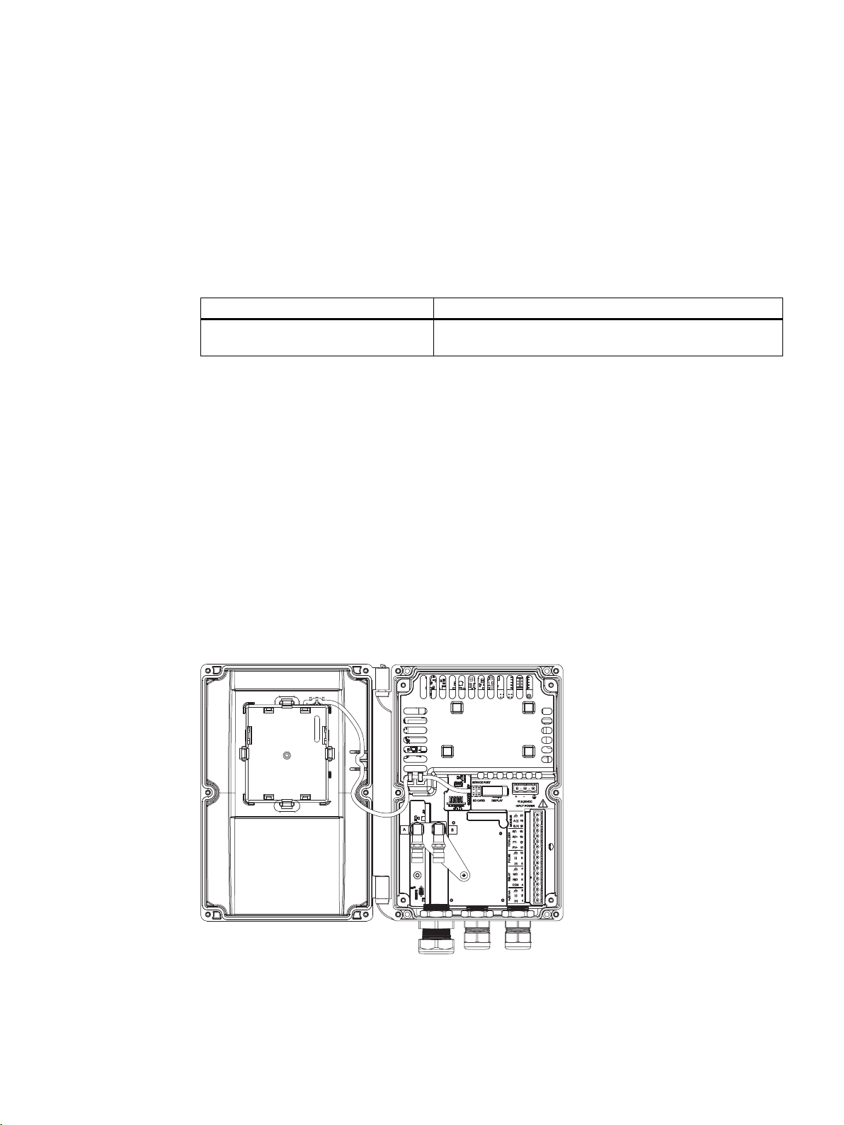
5.4.3 Connecting Inputs/Outputs
1. Remove blind plugs where required from the flowmeter case.
2. Loosen spring screws on housing lid.
3. Open housing lid.
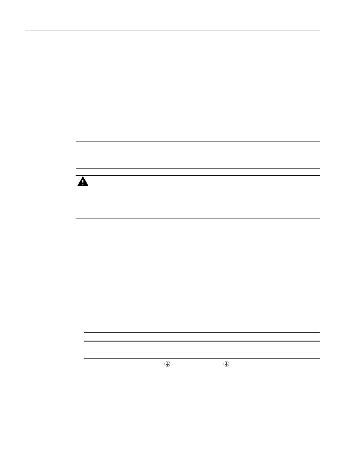
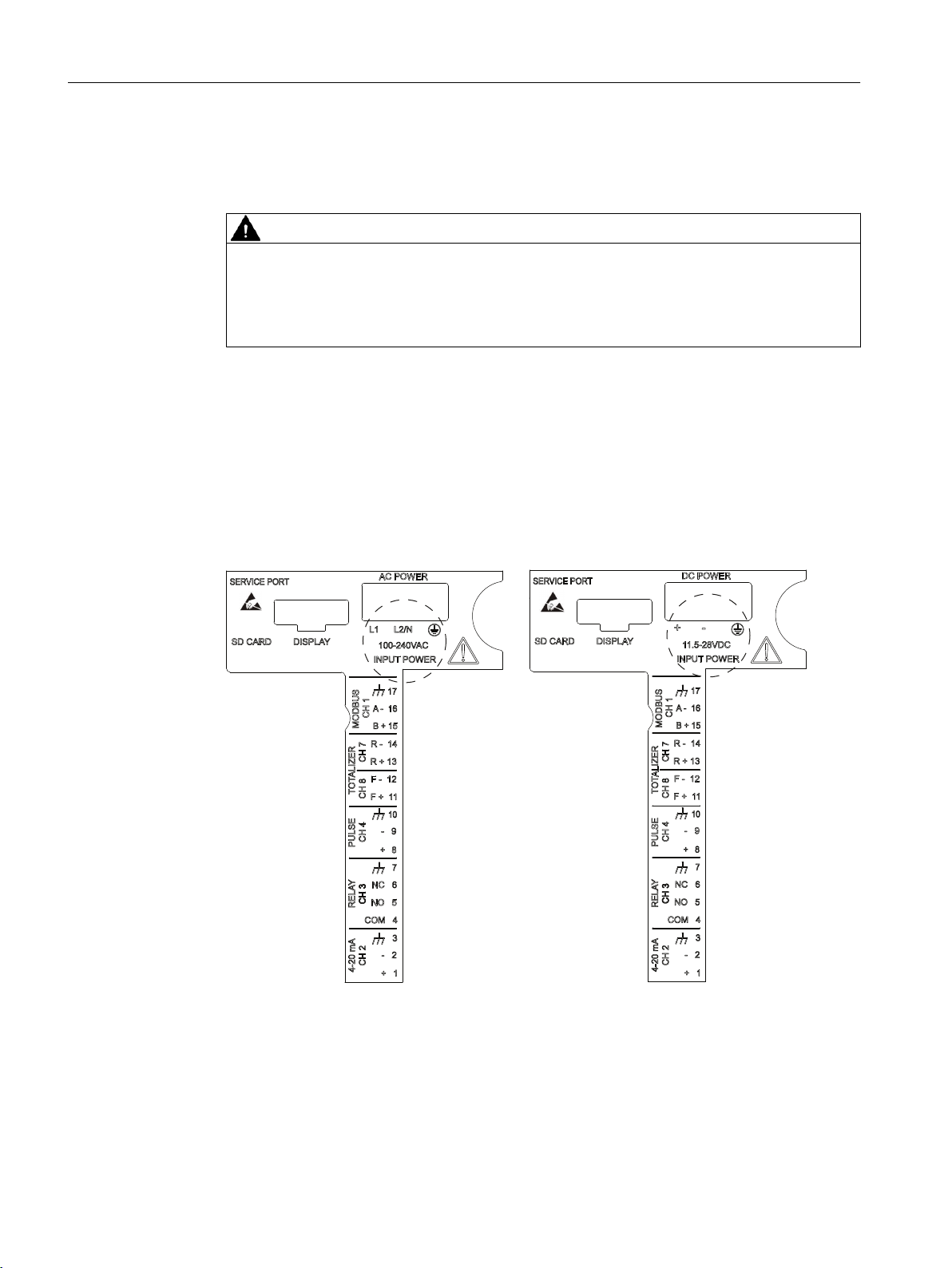
A label showing the device configuration is placed on the PC board inside the transmitter
housing. It is either for AC or DC power depending on the flowmeter type.
Figure 5-3 Inside cover - AC and DC labels
FST020 IP65 NEMA 4X
30 Operating Instructions, 09/2017, A5E41425845-AB
 Loading...