

Page 1
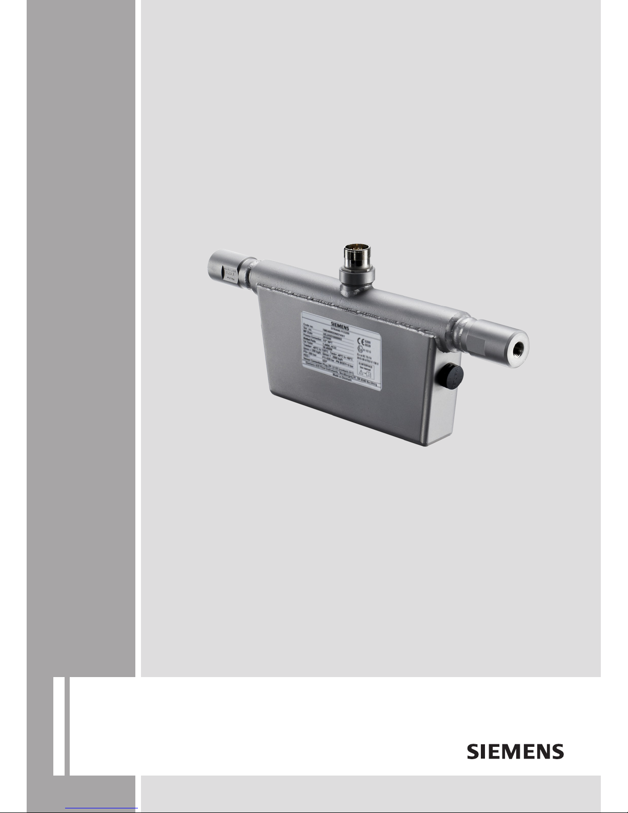
Coriolis flowmeters
SITRANS FCS200
Operating instructions • 02/2011
SITRANS F
Page 2

Page 3
1
Introduction
2
Safety notes
3
Description
SITRANS F
4
Installing/Mounting
Coriolis Flowmeters
SITRANS FCS200
5
Connecting
6
Commissioning
Operating Instructions
7
Service and maintenance
8
Troubleshooting/FAQs
9
Technical data
A
Appendix
Coriolis flow sensor for use with SITRANS F C
transmitter types SIFLOW FC070 and MASS 6000
02/2011
A5E02508199-01
Page 4

Legal information
Warning notice system
This manual contains notices you have to observe in order to ensure your personal safety, as well as to prevent
damage to property. The notices referring to your personal safety are highlighted in the manual by a safety alert
symbol, notices referring only to property damage have no safety alert symbol. These notices shown below are
graded according to the degree of danger.
DANGER
indicates that death or severe personal injury will result if proper precautions are not taken.
WARNING
indicates that death or severe personal injury may result if proper precautions are not taken.
CAUTION
with a safety alert symbol, indicates that minor personal injury can result if proper precautions are not taken.
CAUTION
without a safety alert symbol, indicates that property damage can result if proper precautions are not taken.
NOTICE
indicates that an unintended result or situation can occur if the corresponding information is not taken into
account.
If more than one degree of danger is present, the warning notice representing the highest degree of danger will
be used. A notice warning of injury to persons with a safety alert symbol may also include a warning relating to
property damage.
Qualified Personnel
The product/system described in this documentation may be operated only by personnel qualified for the specific
task in accordance with the relevant documentation for the specific task, in particular its warning notices and
safety instructions. Qualified personnel are those who, based on their training and experience, are capable of
identifying risks and avoiding potential hazards when working with these products/systems.
Proper use of Siemens products
Note the following:
WARNING
Siemens products may only be used for the applications described in the catalog and in the relevant technical
documentation. If products and components from other manufacturers are used, these must be recommended
or approved by Siemens. Proper transport, storage, installation, assembly, commissioning, operation and
maintenance are required to ensure that the products operate safely and without any problems. The permissible
ambient conditions must be adhered to. The information in the relevant documentation must be observed.
Trademarks
All names identified by ® are registered trademarks of the Siemens AG. The remaining trademarks in this
publication may be trademarks whose use by third parties for their own purposes could violate the rights of the
owner.
Disclaimer of Liability
We have reviewed the contents of this publication to ensure consistency with the hardware and software
described. Since variance cannot be precluded entirely, we cannot guarantee full consistency. However, the
information in this publication is reviewed regularly and any necessary corrections are included in subsequent
editions.
Siemens AG order number: A5E02508199 Copyright © Siemens AG 2011.
Industry Sector Ⓟ 04/2011 Technical data subject to change
Postfach 48 48
90026 NÜRNBERG
GERMANY
Page 5

SITRANS FCS200
Operating Instructions, 02/2011, A5E02508199-01
3
Table of contents
1 Introduction................................................................................................................................................ 5
1.1 Items supplied................................................................................................................................5
1.2 Device identification.......................................................................................................................5
1.3 History............................................................................................................................................6
1.4 Further Information ........................................................................................................................7
1.5 Notes on warranty..........................................................................................................................7
2 Safety notes............................................................................................................................................... 9
2.1 General safety instructions ............................................................................................................9
2.2 Laws and directives .......................................................................................................................9
2.3 Installation in hazardous area......................................................................................................10
2.4 Certificates ...................................................................................................................................12
3 Description............................................................................................................................................... 13
3.1 Theory of operation......................................................................................................................14
4 Installing/Mounting................................................................................................................................... 15
4.1 Installation safety precautions......................................................................................................15
4.2 Orienting the sensor.....................................................................................................................16
4.3 Mounting the sensor ....................................................................................................................17
5 Connecting .............................................................................................................................................. 19
5.1 Wiring FCS200.............................................................................................................................20
6 Commissioning ........................................................................................................................................ 21
6.1 Zero point adjustment ..................................................................................................................21
7 Service and maintenance ........................................................................................................................ 23
7.1 Maintenance.................................................................................................................................23
7.2 Recalibration ................................................................................................................................23
7.3 Unit repair.....................................................................................................................................23
7.4 Technical support.........................................................................................................................24
7.5
Transportation and storage..........................................................................................................25
7.6 Return procedures .......................................................................................................................25
7.7 Disposal .......................................................................................................................................26
Page 6

Table of contents
SITRANS FCS200
4 Operating Instructions, 02/2011, A5E02508199-01
8 Troubleshooting/FAQs............................................................................................................................. 27
8.1 General information..................................................................................................................... 27
8.2 Step 1: Inspecting the application ............................................................................................... 27
8.3 Step 2: Improving the application................................................................................................ 28
9 Technical data ......................................................................................................................................... 29
9.1 Pressure / temperature range ..................................................................................................... 30
9.2 Pressure drop.............................................................................................................................. 31
9.3 Electrical connection schematics................................................................................................ 32
9.4 Dimensions ................................................................................................................................. 34
A Appendix.................................................................................................................................................. 37
A.1 Ordering ...................................................................................................................................... 37
A.2 Serial number structure............................................................................................................... 37
Glossary .................................................................................................................................................. 39
Index........................................................................................................................................................ 41
Page 7

SITRANS FCS200
Operating Instructions, 02/2011, A5E02508199-01
5
Introduction
1
These instructions contain all the information you need for using the device.
The instructions are aimed at persons mechanically installing the device, connecting it
electronically, configuring the parameters and commissioning it as well as service and
maintenance engineers.
Note
It is the responsibilit
y of the customer that the instructions and directions provided in the
operating instructions are read, understood and followed by the relevant personnel before
installing the device.
1.1 Items supplied
SITRANS FCS200
Sensorprom Memory unit
Calibration certificate
Quick Start Guide
SITRANS F C Literature CD-ROM
1.2 Device identification
Inspection
1. Check for mechanical damage due to possible improper handling during shipment. All
claims for damage are to be made promptly to the shipper.
2. Make sure the scope of delivery, and the information on the type plate corresponds to the
ordering information
Page 8
Introduction
1.3 History
SITRANS FCS200
6 Operating Instructions, 02/2011, A5E02508199-01
Identification
([LD,,&77
%96$7(;(;
(;&,7(5&,5&8,7(&
,6,17(5)$&(
6HH0DQXDO
6LHPHQV$6)ORZ,QWUXPHQWV1RUGERUJYHM1RUGERUJ
0DGHLQ*HUPDQ\
6,75$16)&6
,,*
C US
$33529('
CI, I, DIV 1,GPS ABCD, T*
Controldrawing nr. A5E03442871A
Entity
Intrinsically
safe for:
2UGHU1R
6HULDO1R
&RQQHFWLRQ
0DWHULDO
&DO)DFWRU
7PHGLD
4PLQ
36
0('1$$
+(-$
ರ137
8161
r&WRr&7DPS r&WRr&
NJK4PD[ NJK
EDU37 31%RG\ EDU
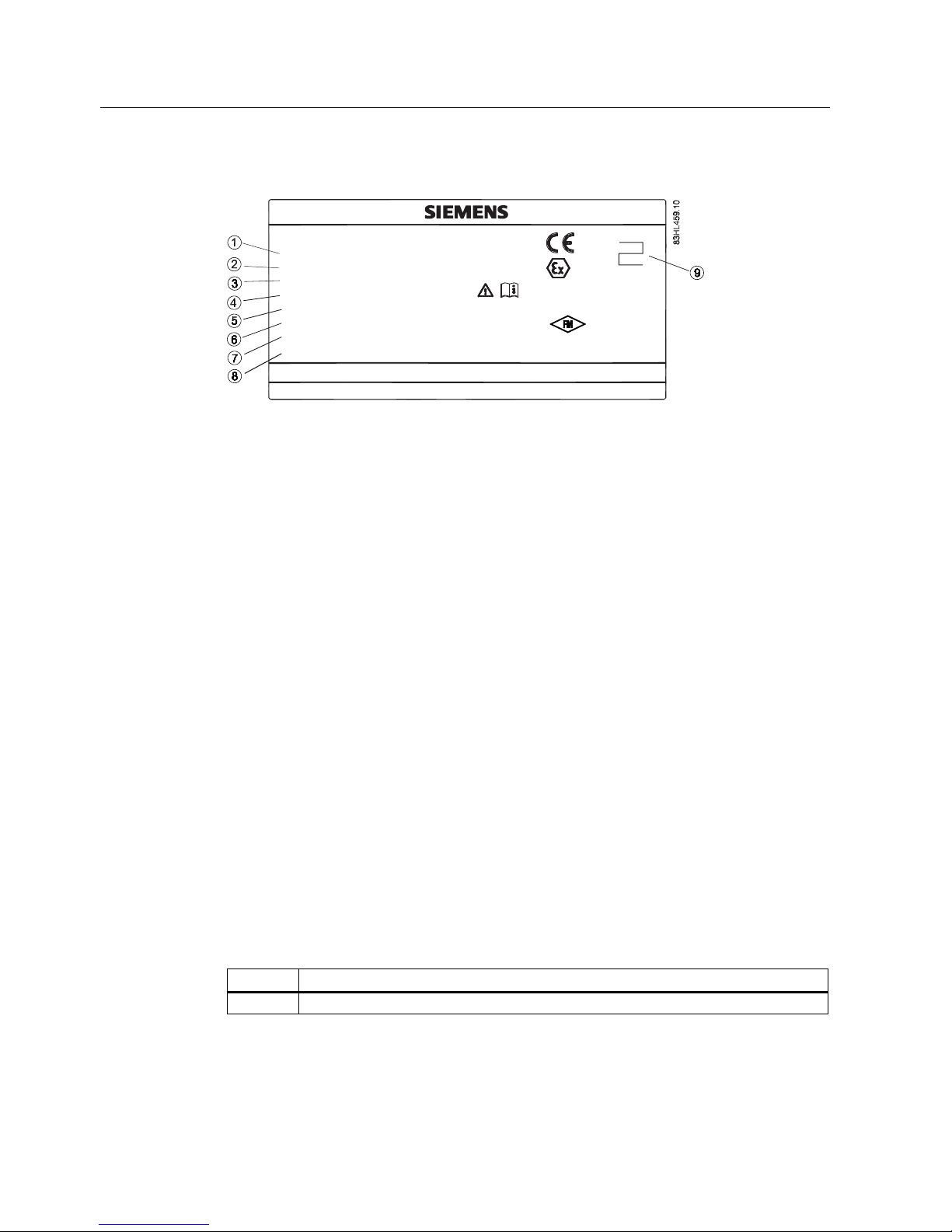
① Order No. Device specific code number
② Serial No. Device specific serial number
③ Connection Process connector type
④ Material Tube material designation
⑤ Cal. Factor Calibration factor and temperature parameter
Tmedia Process media temperature
⑥
Tamb Ambient temperature
Qmin Minimum measuring capacity
⑦
Qmax Maximum measuring capacity
PS Maximum permissible process pressure
⑧
PT
Test pressure
PN Body
Maximum permissible enclosure pressure
⑨ PTB Approval number
Figure 1-1 FCS200 Nameplate example
See also
Serial number structure (Page 37)
1.3 History
The contents of these instructions are regularly reviewed and corrections are included in
subsequent editions. We welcome all suggestions for improvement.
The following table shows the most important changes in the documentation compared to
each previous edition.
Edition Remarks
02/2011 First edition
Page 9

Introduction
1.4 Further Information
SITRANS FCS200
Operating Instructions, 02/2011, A5E02508199-01
7
1.4 Further Information
Product information on the Internet
The Operating Instructions are available on the CD-ROM shipped with the device, and on
the Internet on the Siemens homepage, where further information on the range of SITRANS
F flowmeters may also be found:
Product information on the internet (http://www.siemens.com/flowdocumentation
)
Worldwide contact person
If you need more information or have particular problems not covered sufficiently by these
Operating Instructions, get in touch with your contact person. You can find contact
information for your local contact person on the Internet:
Local contact person (http://www.automation.siemens.com/partner
)
See also
Technical support (Page 24)
1.5 Notes on warranty
The contents of this manual shall not become part of or modify any prior or existing
agreement, commitment or legal relationship. The sales contract contains all obligations on
the part of Siemens as well as the complete and solely applicable warranty conditions. Any
statements regarding device versions described in the manual do not create new warranties
or modify the existing warranty.
The content reflects the technical status at the time of publishing. Siemens reserves the right
to make technical changes in the course of further development.
Page 10

Introduction
1.5 Notes on warranty
SITRANS FCS200
8 Operating Instructions, 02/2011, A5E02508199-01
Page 11

SITRANS FCS200
Operating Instructions, 02/2011, A5E02508199-01
9
Safety notes
2
2.1 General safety instructions
CAUTION
Correct, reliable operation of the product requires proper transport, storage, positioning and
assembly as well as careful operation and maintenance. Only qualified personnel should
install or operate this instrument.
Note
Alterations to the product, including opening or improper modifications of the product, are not
permitted.
If this requirement is not observed, the CE mark and the manufacturer's warranty will expire.
2.2 Laws and directives
General requirements
Installation of the equipment must comply with national regulations. For example EN 6007914 for the European Community.
Instrument safety standards
The device has been tested at the factory, based on the safety requirements. In order to
maintain this condition over the expected life of the device the requirements described in
these Operating Instructions must be observed.
CE marked equipment
The CE-mark symbolizes the compliance of the device with the following directives:
● EMC directive 2004/108EC
● Pressure equipment directive (PED/DGRL) 97/23/EC
● ATEX directive 94/9/EC
Page 12

Safety notes
2.3 Installation in hazardous area
SITRANS FCS200
10 Operating Instructions, 02/2011, A5E02508199-01
2.3 Installation in hazardous area
WARNING
Equipment used in hazardous areas must be Ex-approved and marked accordingly. It is
required that the special conditions for safe use provided in the manual and in the Ex
certificate are followed!
Hazardous area approvals
The device is approved for use in hazardous area and has the following approval:
● II 1/2 G Ex ia IIC T5-T4
WARNING
Make sure the hazardous area approval is suitable for the environment in which the
device will be installed.
WARNING
Due to the increased safety concept, SITRANS F C MASS 6000 and SIFLOW FC070
Ex have to be mounted in the safe area.
SITRANS F C MASS 6000 Ex d is allowed for use in hazardous area
Intrinsically safe data
Table 2- 1 Exciter circuit, DN10 and DN15
Exciter circuit EC1 (Terminal 1-2), DN10 and DN15
Ui 30 V DC
Ii 130 mA
Pi 0.5 W
Ci Insignificant
Li 2 mH
Table 2- 2 Exciter circuit, DN25
Exciter circuit EC2 (Terminal 1-2), DN25
Vo 30 V DC
Io 130 mA
Po 0.5 W
Connection of an intrinsically safe circuit level of protection Ex ia and the following maximum values
Page 13

Safety notes
2.3 Installation in hazardous area
SITRANS FCS200
Operating Instructions, 02/2011, A5E02508199-01
11
Table 2- 3 Sensor circuit
Sensor circuit (Terminal 5-6 and 7-8)
Ui 30 V DC
Ii 50 mA
Pi 0.4 W
Ci Insignificant
Li 14 mH
Uo 0.3 V AC
Temperature specifications for use in hazardous area
Table 2- 4 Temperature specifications
Temperature class Max. process temperature [°C] Ambient temperature [°C]
T4 125 -40 ... +60
T5 70 -40 ... +60
Special conditions for safe use
It is required that:
● Electrical connections are in accordance with IEC/EN60079-14 (Installing Electrical
Systems in Explosion Hazardous Areas).
● The protective cover over the power supply is properly installed. For intrinsically safe
circuits the connection area can be opened.
● Appropriate cable connectors are used for the output circuits:
– Intrinsically safe: blue
– Non-intrinsically safe: black
● Sensor and transmitter are connected to potential equalization.
For intrinsically safe output circuits potential equalization must be maintained along the
entire connection path.
● When protective earth (PE) is connected, no potential difference between the protective
earth (PE) and the potential equalization (PA) can exist, even during a fault condition.
Page 14

Safety notes
2.4 Certificates
SITRANS FCS200
12 Operating Instructions, 02/2011, A5E02508199-01
2.4 Certificates
Certificates are posted on the Internet and on the documentation CD-ROM shipped with the
device.
See also
Certificates (http://www.siemens.com/processinstrumentation/certificates)
UL control drawings on the internet (http://www.automation.siemens.com/w1/automation-
technology-process-instrumentation-18092.htm#lb-61,related-installationdrawings)
Page 15
SITRANS FCS200
Operating Instructions, 02/2011, A5E02508199-01
13
3
Description
Applications
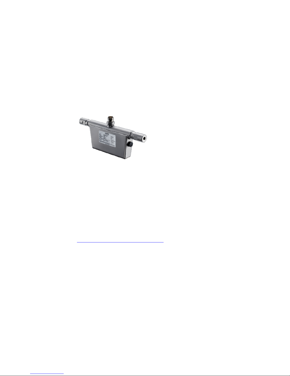
SITRANS FCS200 is designed for measurement of compressed natural gas (CNG) and is
suitable for filling of gas bottles, furnace control and dispensing.
Figure 3-1 SITRANS FCS200
System components
SITRANS FCS200 makes up the sensor part of a Coriolis flowmeter. The other part is the
transmitter.
SITRANS FCS200 can be remote mounted with the following transmitter types:
● SIFLOW FC070 and SIFLOW FC070 Ex
● SITRANS F C MASS 6000, MASS 6000 Ex and SITRANS F C MASS 6000 Ex d
Further information about the transmitter can be found in the relevant Operating Instructions
available on the SITRANS F literature CD-ROM or on the flow documentation webpage
(http://www.siemens.com/flowdocumentation
).
Design
SITRANS FCS200 is available in DN10, DN15 and DN25.
The sensor consists of 2 parallel measuring pipes, welded directly onto a flow splitter at each
end of the sensor. The flow-splitters are welded directly onto a rigid sensor housing which
acts as a mechanical low pass filter.
The wetted parts of SITRANS FCS200 are available in Hastelloy C-22, while the enclosure is
made of stainless steel W 1.4404 (AISI 304) with a grade of encapsulation of IP66 / IP67
(NEMA 4X).
Page 16
Description
3.1 Theory of operation
SITRANS FCS200
14 Operating Instructions, 02/2011, A5E02508199-01
Table 3- 1 Pressure / Measurement
Pressure Max. massflow
DN10 PN350 42 kg/min
DN15 PN350 200 kg/min
DN25 PN214 500 kg/min
3.1 Theory of operation
The flow measuring principle is based on the Coriolis law of motion.
Particles moving in a rotating / oscillating system will resist the imposed oscillations in a
manner consistent with the mass and velocity (momentum). Oscillations produced by a
Coriolis flowmeter as the process media is accelerated around bends result in phase
distortions of the measuring tubes.
The SITRANS F C sensors are energized by an electromechanical driver circuit which
oscillates the pipe at its resonant frequency. Two pickups, S1 and S2, are placed
symmetrically on either side of the driver.
When the media flows through the sensor, Coriolis force will act on the measuring tube and
cause a tube deflection which can be measured as a phase shift between pickup S1 and
pickup S2.
The phase shift is proportional to the mass flowrate. The frequency and amplitude of the
driver is automatically regulated to ensure a stable output from the 2 pickups in the region of
80 to 110 mV. The temperature of the sensor tubes is measured by a Pt1000, in order to
enable accurate compensation for changes in the material stiffness. As a result the process
media temperature is also accurately measured.
The flow proportional phase signal from the pickups, the temperature measurement and the
driver frequency enable calculation and reporting of mass, density, volume, and temperature.
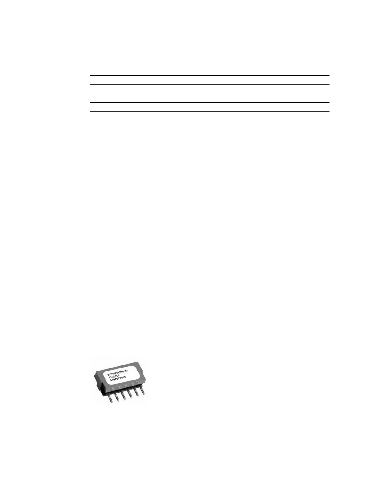
SENSORPROM
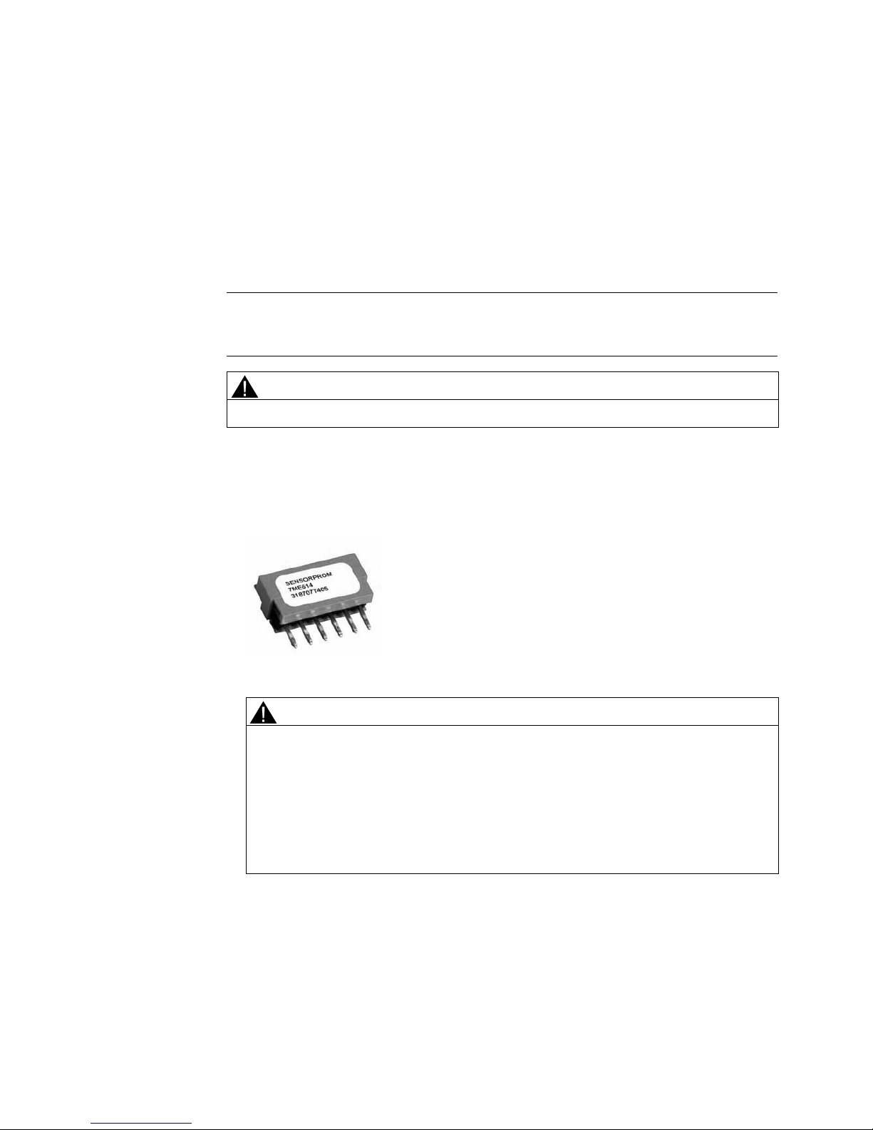
All SITRANS F C Coriolis flow meters feature a SENSORPROM memory unit which stores
sensor-specific calibration data and transmitter settings for the lifetime of the product. The
factory settings matching the sensor are stored in the SENSORPROM. At commissioning the
flow meter commences a typical flow measurement without any initial programming. Also
customer-specified settings are downloaded to the SENSORPROM.
Figure 3-2 SENSORPROM memory unit
Page 17

SITRANS FCS200
Operating Instructions, 02/2011, A5E02508199-01
15
4
Installing/Mounting
SITRANS F flowmeters with minimum IP67/NEMA 4X enclosure rating are suitable for indoor
and outdoor installations.
● Make sure that pressure and temperature specifications indicated on the device
nameplate / label will not be exceeded.
WARNING
Installation in hazardous location
Special
requirements apply to the location and interconnection of sensor and
transmitter. See "Installation in hazardous area" (Page 10)
4.1 Installation safety precautions
WARNING
In applications with working pressures/media that can be dangerous to people,
surroundings, equipment or others in case of pipe fracture, we recommend that special
precautions such as special placement, shielding or installation of a security guard or a
security valve are taken when the sensor is mounted.
● Ensure that stresses and loading caused by earthquakes, traffic, high winds and fire
damage if appropriate are taken into account during installation.
● Ensure that the flowmeter is installed such that it does not act as a focus for pipeline
stresses. External loadings are not taken into account during flowmeter design.
● Provide adequate protection to minimise any risk of contact with hot surfaces.
WARNING
Prevent personal injuries by assurin
g that operation below pressure guards cannot take
place, if working with vacuum or fluids boiling readily.
Page 18
Installing/Mounting
4.2 Orienting the sensor
SITRANS FCS200
16 Operating Instructions, 02/2011, A5E02508199-01
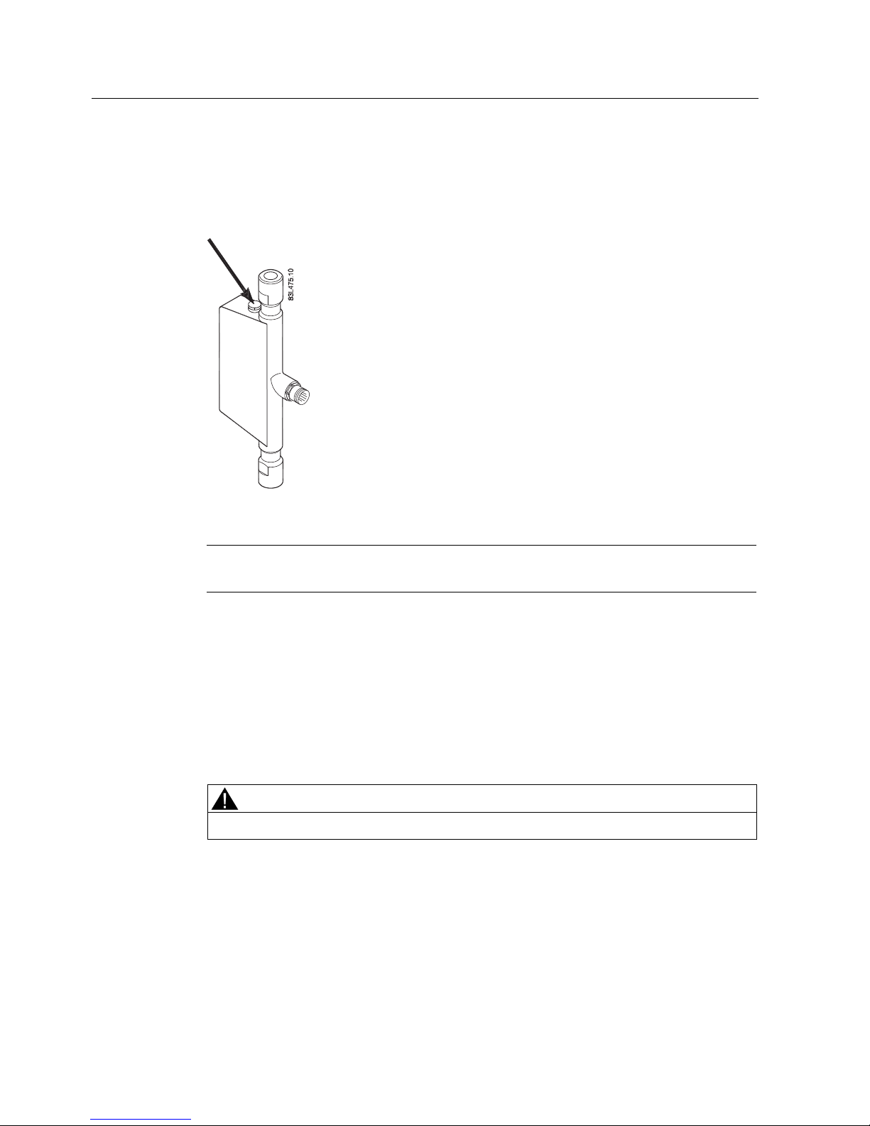
Rupture disc
The two black rupture discs prevent overpressure in the enclosure. In case of a tube fracture
generating overpressure in the enclosure, the rupture discs will immediately burst and keep
the pressure at a safe level.
Figure 4-1 Rupture safety disc
Note
The enc
losure of the sensor does not fulfil any containment function.
4.2 Orienting the sensor
Flow direction
The calibrated flow direction is indicated by the arrow on the sensor. Flow in this direction
will be indicated as positive (a forward/reverse flow calibration is available as an option).
CAUTION
The sensor must always be completely filled with gas in order to measure accurately.
Page 19
Installing/Mounting
4.3 Mounting the sensor
SITRANS FCS200
Operating Instructions, 02/2011, A5E02508199-01
17
Orienting the sensor
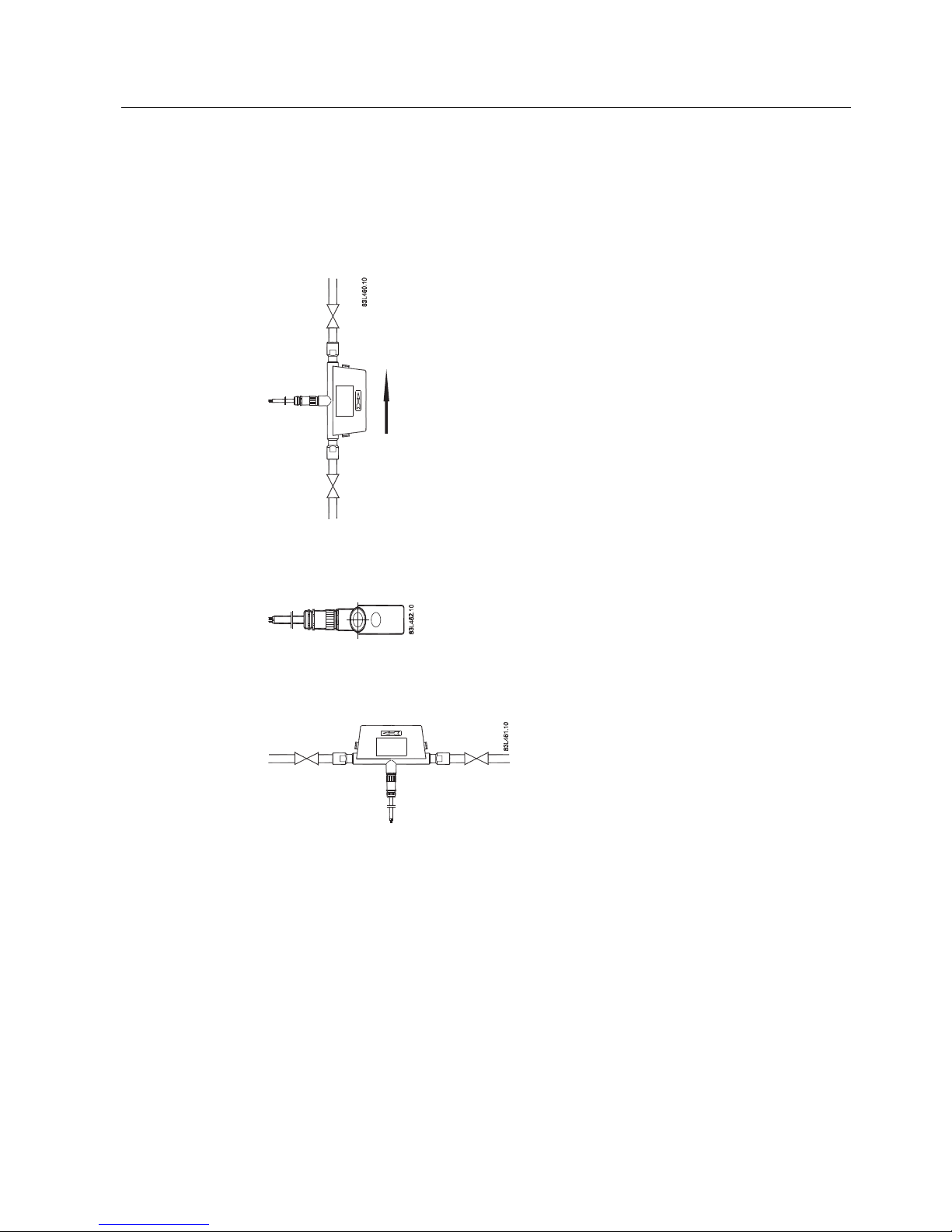
SITRANS FCS200 operates in any orientation, but Siemens recommends orienting the
sensor in one of the following ways:
1. Vertical orientation with an upwards flow
Figure 4-2 Vertical orientation, upwards flow
2. Horizontal installation, tubes sideways
Figure 4-3 Horizontal mounting, tubes sideways
3. Horizontal installation, tubes up
Figure 4-4 Horizontal orientation; tubes up
4.3 Mounting the sensor
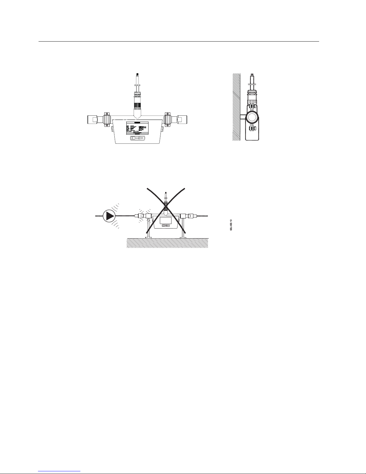
● Install two pipe hangers with rubber inserts symmetrically and stress free on the
enclosure ends as shown below.
Sensor end dimensions are described in the Dimensions chapter (Page 34) of the
Operating Instruction
s.
● Mount the pipe hangers on a solid, vibration free foundation or frame
● Center the connecting pipelines axially in order to assure a stress-free installation.
Page 20
Installing/Mounting
4.3 Mounting the sensor
SITRANS FCS200
18 Operating Instructions, 02/2011, A5E02508199-01
/
SITRANS FCS200
/
Avoid vibrations
● Make sure that any valves or pumps upstream of the sensor do not cavitate and do not
send vibration into the sensor.
Figure 4-5 Eliminate vibrations
Avoid cross talk
If operating more than one flowmeter in one or multiple interconnected pipelines there is a
risk of cross talk.
Prevent cross talk as follows:
● Mount sensors on separate steelframes
● Keep sufficient distance between the sensors (distance depends on application)
● Decouple the pipelines.
Page 21
SITRANS FCS200
Operating Instructions, 02/2011, A5E02508199-01
19
5
Connecting
The following contains a short description of how to connect the sensor for operation with a
SITRANS F C MASS 6000 or SIFLOW FC070 transmitter.
Note
For mo
re information, including information about connecting the sensor to the transmitter,
refer to the Operating Instructions for the respective transmitters.
WARNING
Only qualified personnel may carry out work on the electrical connections.
Before connecting
● Check that serial numbers on sensor and SENSORPROM® unit are identical.
Figure 5-1 Sensorprom
WARNING
Use in hazardous locations
Before connecting check that:
No explosion hazard exists
A fire department permission certificate has been issued
All connection leads are potential free
Special requirements apply to the location and interconnection of sensor and
transmitter. See "Installation in hazardous area" (Page 10)
Page 22

Connecting
5.1 Wiring FCS200
SITRANS FCS200
20 Operating Instructions, 02/2011, A5E02508199-01
5.1 Wiring FCS200
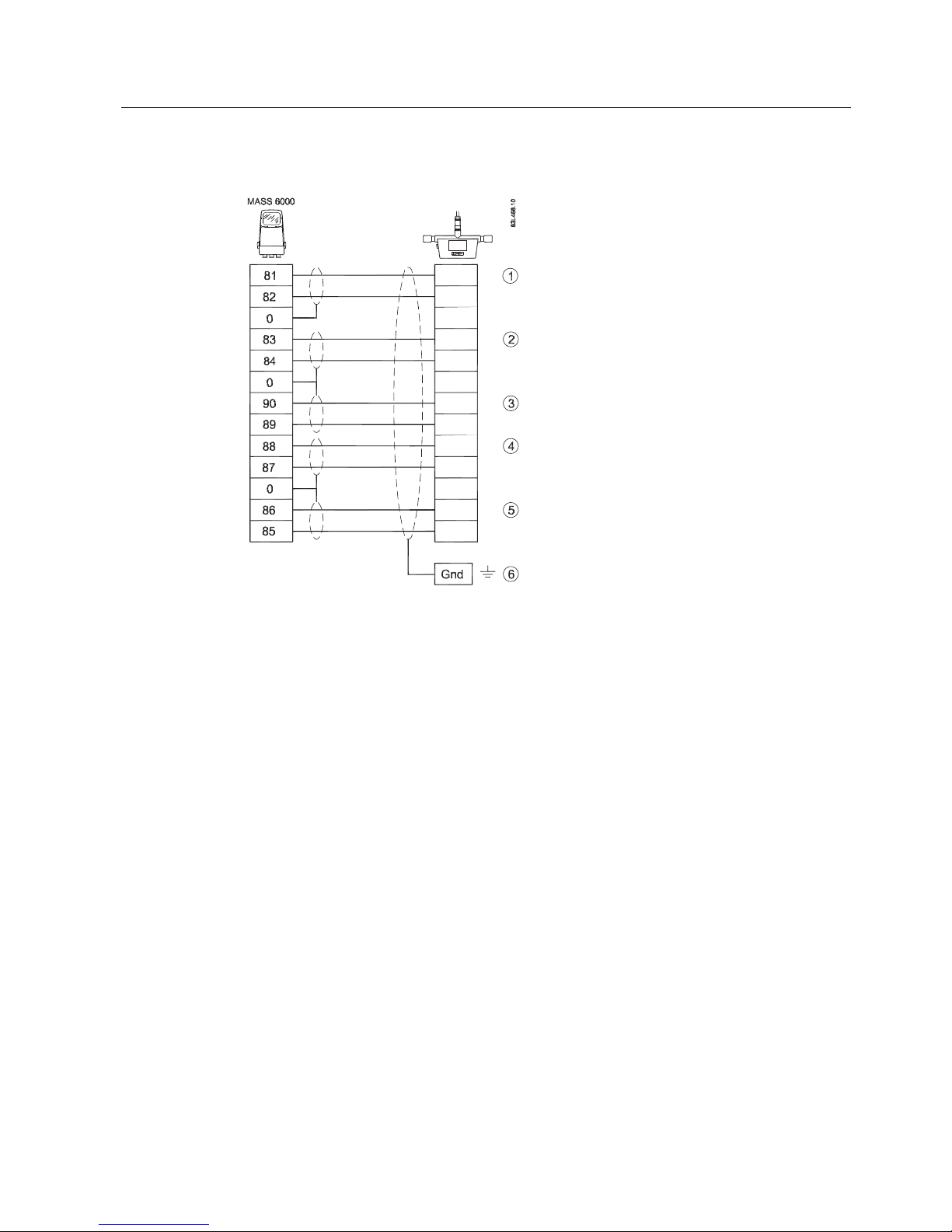
1. Connect transmitter and sensor using a SITRANS F C standard blue cable.
Figure 5-2 Electrical connection of sensor
WARNING
Only commission the device after it has been properly connected and, if required,
closed.
Note
Orde
ring information
Find SITRANS F C standard blue cable order information in the FI01 catalog: Catalog
process instrumentation (http://www.siemens.com/processinstrumentation/catalogs
).
See also
Electrical connection schematics (Page 32)
Page 23

SITRANS FCS200
Operating Instructions, 02/2011, A5E02508199-01
21
6
Commissioning
Before commissioning it must be checked that:
● The device has been installed and connected in accordance with the guidelines provided
in chapter 4 "Installing / Mounting (Page 15)" and 5 "Connecting (Page 19)"
● De
vice installed in hazardous location meets the requirements described in "Installation in
hazard
ous location (Page 10)"
6.1 Zero point adjustment
Commissioning the device includes performing a zero point adjustment. In the following it is
described how to prepare for a zero point adjustment, and how to activate an auto zero point
adjustment.
Before zero point adjusting
● Make sure the shut-off valves before and after the sensor are fully opened.
Figure 6-1 Installation with shut-off valves
Auto zero point adjustment
1. Power up and acclimate the transmitter (min. 30 min).
2. Pump gas at max. flow through the sensor (min. 2 min).
Page 24

Commissioning
6.1 Zero point adjustment
SITRANS FCS200
22 Operating Instructions, 02/2011, A5E02508199-01
3. Stop the flow while pumping by closing the outlet valve and then the inlet valve
Note
The flow must be completely stopped and the sensor completely filled with gas.
The zero point adjustment has to be carried out under stable pressure conditions.
4. Perform an auto zero point adjustment:
MASS 6000 SIFLOW FC070
Choose menu entry "Reset mode"
-> Zero adjust
-> Zero adjust auto
-> Zero adjust
Choose the SIMATIC PDM menu
-> Device
-> zero adjust
5. After count down (30 s.), the actual zero point is displayed and the meter ready for
operation.
See also
For further information on performing an auto zero point adjustment, refer to the relevant
transmitter Operating Instructions.
Page 25

SITRANS FCS200
Operating Instructions, 02/2011, A5E02508199-01
23
Service and maintenance
7
7.1 Maintenance
The device is maintenance-free, however, a periodic inspection according to pertinent
directives and regulations must be carried out.
An inspection can include check of:
● Ambient conditions
● Seal integrity of the process connections, cable entries, and cover screws
● Reliability of power supply, lightning protection, and grounds
7.2 Recalibration
Siemens A/S Flow Instruments offers to recalibrate the sensor. The following calibrations are
offered as standard:
● Standard matched pair calibration
Note
For recalibration the memory unit must always be returned with the sensor
7.3 Unit repair
CAUTION
Repair and service must be carried out by Siemens authorized personnel only.
Note
Siemens defines flow sensors as non-repairable products.
Page 26

Service and maintenance
7.4 Technical support
SITRANS FCS200
24 Operating Instructions, 02/2011, A5E02508199-01
7.4 Technical support
If you have any technical questions about the device described in these Operating
Instructions and do not find the right answers, you can contact Technical Support:
● Via the Internet using the Support Request:
Support request (http://www.siemens.com/automation/support-request
)
● Via Phone:
– Europe: +49 (0)911 895 7222
– America: +1 423 262 5710
– Asia-Pacific: +86 10 6475 7575
Further information about our technical support is available in the Internet at
Technical support (http://support.automation.siemens.com/WW/vi
ew/en/16604318)
Service & Support on the Internet
In addition to our documentation, we offer a comprehensive knowledge base online on the
Internet at:
Service and support (http://www.siemens.com/autom
ation/service&support)
There you will find:
● The latest product information, FAQs, downloads, tips and tricks.
● Our newsletter, providing you with the latest information about your products.
● A Knowledge Manager to find the right documents for you.
● Our bulletin board, where users and specialists share their knowledge worldwide.
● You can find your local contact partner for Industry Automation and Drives Technologies
in our partner database.
● Information about field service, repairs, spare parts and lots more under "Services."
Additional Support
Please contact your local Siemens representative and offices if you have additional
questions about the device
Find your contact partner at:
Local contact person (http://www.automation.siemens.com/partner
)
Page 27

Service and maintenance
7.5 Transportation and storage
SITRANS FCS200
Operating Instructions, 02/2011, A5E02508199-01
25
7.5 Transportation and storage
To guarantee sufficient protection during transport and storage, observe the following:
● Keep the original packaging for subsequent transportation.
● Devices/replacement parts should be returned in their original packaging.
● If the original packaging is no longer available, ensure that all shipments are properly
packaged to provide sufficient protection during transport. Siemens cannot assume
liability for any costs associated with transportation damages.
CAUTION
Insufficient protection during storage
The packaging only provides limited protection against moisture and infiltration.
Provide additional packaging as necessary.
Special conditions for storage and transportation of the device are listed in Chapter
"Technical data (Page 29)".
7.6 Return procedures
Enclose the delivery note, the cover note for return delivery together with the declaration of
decontamination form on the outside of the package in a well-fastened clear document
pouch.
Required forms
● Delivery Note
● Cover Note for Return Delivery with the following information
Cover note (http://support.automation.siemens.
com/WW/view/en/16604370)
– product (ordering number)
– number of devices or spare parts returned
– reason for the return
● Declaration of Decontamination
Declaration of Decontamination
(http://pia.khe.siemens.com/efiles/feldg/files
/Service/declaration_of_decontamination_en.
pdf)
With this declaration you certify
that the returned products/spare parts have been
carefully cleaned and are free from any residues.
Page 28

Service and maintenance
7.7 Disposal
SITRANS FCS200
26 Operating Instructions, 02/2011, A5E02508199-01
If the device has been operated together with toxic, caustic, flammable or waterdamaging products, clean the device before return by rinsing or neutralizing. Ensure that
all cavities are free from dangerous substances. Then, double-check the device to ensure
the cleaning is completed.
We shall not service a device or spare part unless the declaration of decontamination
confirms proper decontamination of the device or spare part. Shipments without a
declaration of decontamination shall be cleaned professionally at your expense before
further proceeding.
You can find the forms on the Internet and on the CD delivered with the device.
7.7 Disposal
Devices identified by this symbol may not be disposed of in the
municipal waste disposal services under observance of the
Directive 2002/96/EC on waste electronic and electrical
equipment (WEEE).
They can be returned to the supplier within the EC or to a
locally approved disposal service. Observe the specific
regulations valid in your country.
Page 29

SITRANS FCS200
Operating Instructions, 02/2011, A5E02508199-01
27
Troubleshooting/FAQs
8
8.1 General information
Incorrect and unstable measurements, especially at low flows, are typically a result of an
unstable zero point due to:
● Incorrect installation
● Vibrations/Cross talk
In the following a 2 steps guide to troubleshooting is provided:
Step 1 Preliminary application inspection
Step 2 Application improvement
The guide will enable you to trace the reason for incorrect measurements and to improve the
application.
8.2 Step 1: Inspecting the application
The first step in the troubleshooting procedure is to check for some easily resolved
problems.
Check that:
● Sensor and Sensorprom memory unit correspond (serial numbers)
● The sensor is properly installed.
● The sensor is located in a vibration-free position. Vibrations can disturb the sensor and
therefore cause measurement error.
Resolving step 1 problems
1. Make sure that the serial numbers on the sensor and the Sensorprom memory unit are
identical.
2. Make sure that the sensor is installed as described in the installation chapter (Page 15) of
the sen
sor manual.
3. Flush the pipe systems and the sensor for several minutes at maximum flow rate to fill in
the process media.
Page 30

Troubleshooting/FAQs
8.3 Step 2: Improving the application
SITRANS FCS200
28 Operating Instructions, 02/2011, A5E02508199-01
8.3 Step 2: Improving the application
Incorrect installation of the sensor
Especially for low flow rates, i.e. flow rates less than 10% of the maximum capacity of the
flowmeter, it is important that the sensor is correctly and stably installed.
If the sensor is not correctly fixed in place, the zero point of the sensor will move, leading to
measuring errors.
1. Secure that the sensor has been installed and fixed to a solid vibration free foundation or
frame.
2. Tighten the sensor brackets in order to stabilize the flow.
Vibrations and cross talk
Vibrations in the pipe system are normally generated by pumps.
Typically, cross talk is generated by two sensors positioned in close proximity in the same
pipe, or installed on the same rail or frame.
1. Set Low Flow Cut-Off to zero %
2. Turn off any pump to see if the zero point stability improves, i.e. if the flow rate fluctuation
in kg/h is reduced.
If the sensor is disturbed by vibration from a pump, the installation should be improved or
the pump replaced.
3. Check for cross talk.
Turn off the power to the other flowmeter(s) and wait approximately 2 minutes. Then
check if the zero point stability has improved, i.e. that the fluctuation in kg/h has been
reduced. If this is the case, the sensors disturb each another and the installation should
be improved.
Page 31

SITRANS FCS200
Operating Instructions, 02/2011, A5E02508199-01
29
Technical data
9
Table 9- 1 Technical data
DN10 DN15 DN25
Nominal diameter DN10 DN15 DN25
Mass flow measuring range
Min ... max. [kg/h (lbs/min)]
250 (9,2) ...
2.500 (91,9)
1.200 (44,1) ...
12.000 (440,9)
3.000 (110,2) ... 30.000
(1.102,3)
Process temperature [°C
(°F)]
-40...+125 (-40...+257)
Ambient temperature [°C
(°F)]
-40 ... 60 (-40 ... 140)
Nominal pressure [bar (psi)] 350 (5076) 350 (5076) 214 (3104)
Enclosure grade IP 66 / IP 67 (EN60529)
Humidity limit 5 to 95% relative humidity, non-condensing
Vibration limits According to IEC 68.2.6
Endurance sweep 5 ... 2000 Hz
50 sweep cycles at 1.0 g.
Max. pressure drop with
water at 20°C
See chapter: Pressure drop (Page 31)
Dimensions See chapter: Dimensions (Page 34)
Table 9- 2 Materials and weight
DN10 DN15 DN25
Materials
Measuring tube Hastelloy C22
UNS N06022/2.4602
Hastelloy C22
UNS N06022/2.4602
Stainless steel
AISI 316L/1.4571
Splitter Hastelloy C22
UNS N06022/2.4602
Stainless steel
AISI 316L/1.4571
Stainless steel
AISI 316L/1.4571
Enclosure Stainless steel
AISI 304L/1.4404
Stainless steel
AISI 304L/1.4404
Stainless steel
AISI 304L/1.4404
Process connectors
(flanges)
Stainless steel
AISI 304L/1.4301
Stainless steel
AISI 304L/1.4301
Stainless steel
AISI 304L/1.4301
Weight [kg (lb)] 2.8 (6.2) 6.0 (13.2) 11 (24.2)
Page 32

Technical data
9.1 Pressure / temperature range
SITRANS FCS200
30 Operating Instructions, 02/2011, A5E02508199-01
Table 9- 3 Process connectors
DN10 DN15 DN25
NPT
¼" NPT (f) ½" NPT (f)
½" NPT (f) ¾" NPT (f)
1" NPT (f)
1" NPT (f)
1½" NPT (f)
VCO
½ Inch VCO ¾ Inch VCO 1 Inch VCO
Table 9- 4 Accuracy
Mass flow linearity error [% of rate] ±0.5
Repeatability [% of rate] ±0.25
Table 9- 5 Certificates and approvals
Hazardous area approvals ATEX
II 1/2 G Ex ia IIC T5-T4
IECEX IECEX II 1/2 G Ex ia IIC T5-T4
PED According to PED 97/23EC
Fluid group 1
Category Article 3 part 3
Modu
le ≤DN25
9.1 Pressure / temperature range
°C
Figure 9-1 Pressure / temperature range
Page 33

Technical data
9.2 Pressure drop
SITRANS FCS200
Operating Instructions, 02/2011, A5E02508199-01
31
Table 9- 6 Pressure / temperature range
[°C (°F)] -40 (-40) 0 (32) 50 (122) 100 (212) 125 (257)
DN10 350 Bar 350 Bar 350 Bar 346 Bar 325 Bar
DN15 350 Bar 350 Bar 350 Bar 346 Bar 325 Bar
DN25 214 Bar 214 Bar 214 Bar 179 Bar 179 Bar
9.2 Pressure drop
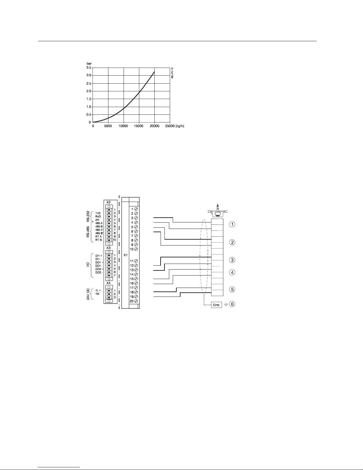
The pressure drop is dimension dependent and influenced by process media viscosity and
density.
The following curves show the pressure loss of water with a pressure of 200bar and at an
ambient temperature of 20 °C:
Figure 9-2 Pressure drop DN10
Figure 9-3 Pressure drop DN15
Page 34
Technical data
9.3 Electrical connection schematics
SITRANS FCS200
32 Operating Instructions, 02/2011, A5E02508199-01
Figure 9-4 Pressure drop DN25
9.3 Electrical connection schematics
Electrical connection of FCS200 and SIFLOW FC070
1
2
3
4
4
3
8
7
6
5
FCS200
/
PU1 +
PU1 Shield Ex
PU2 +
PU2 Shield Ex
T Out +
T Out Shield Ex
Shield Ex
Shield Ex
DRV +
DRV T In +
T In -
Shield
Shield
Shield
① Driver
② PT 1000
③ Pick up 1
④ Pick up 2
⑤ PT 1000
⑥ Ground
Figure 9-5 Electrical connection, FCS200 and SIFLOW FC070
Page 35
Technical data
9.3 Electrical connection schematics
SITRANS FCS200
Operating Instructions, 02/2011, A5E02508199-01
33
Electrical connection of FCS200 and MASS 6000
1
2
3
4
4
3
8
7
6
5
FCS200
① Driver
② PT 1000
③ PT 1000
④ Pick up 2
⑤ Pick up 1
⑥ Ground
Figure 9-6 Electrical connection, FCS200 and MASS 6000
Page 36
Technical data
9.4 Dimensions
SITRANS FCS200
34 Operating Instructions, 02/2011, A5E02508199-01
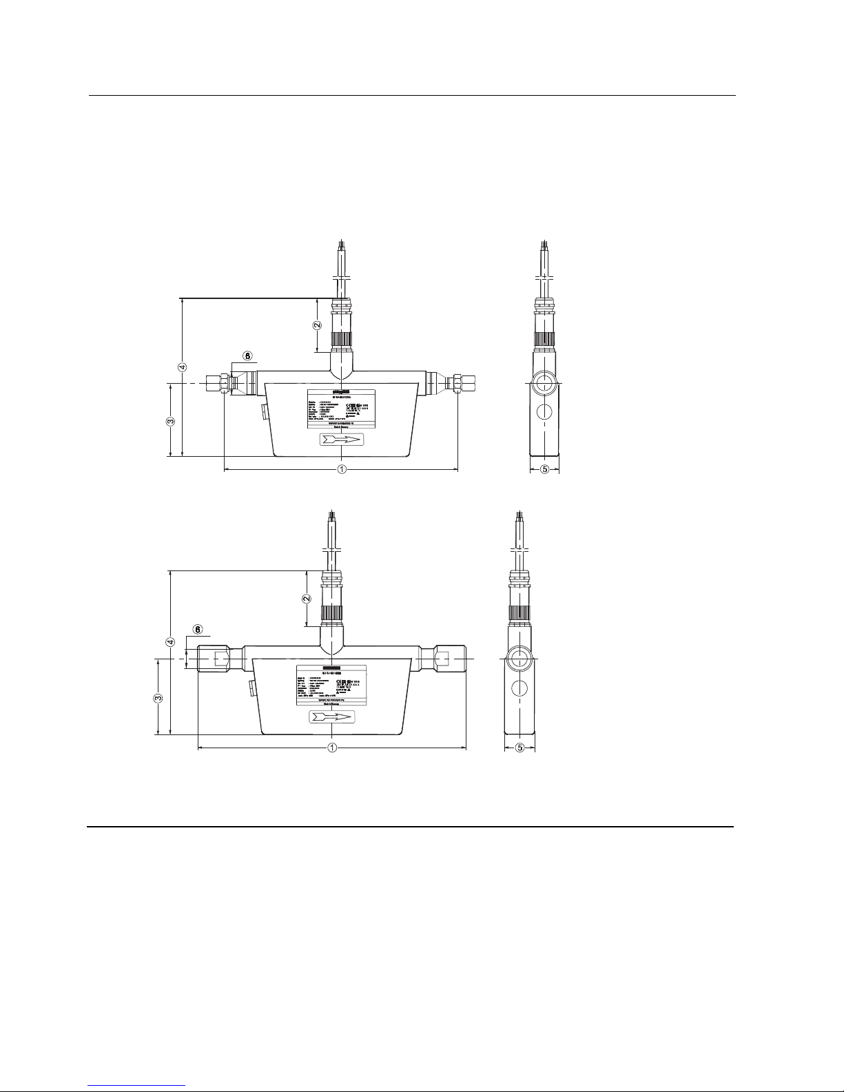
9.4 Dimensions
Dimensions, DN10 and DN15, VCO and NPT connectors
'1'19&2
/
'1'1137
/
Position DN10
with NPT connectors
DN10 DN15
with VCO connectors
[mm (inch)] [mm (inch)] [mm (inch)]
① 350 (13.78) 330 (12.99) 450 (17.72)
② 72 (2.84) 72 (2.84) 72 (2.84)
③ 100 (3.94) 100 (3.94) 148 (5.83)
④ 204 (8.03) 204 (8.03) 253 (9.96)
⑤ 40 (1.57) 40 (1.57) 48 (1.89)
⑥ ∅27 (1) ∅27 (1) ∅48 (1.89)
Figure 9-7 DN 10 - 15 VCO/NPT, dimensions in mm (inch)
Page 37

Technical data
9.4 Dimensions
SITRANS FCS200
Operating Instructions, 02/2011, A5E02508199-01
35
Dimensions, DN25, VCO and NPT connectors
/
'19&2
/
'1137
Position DN25
with NPT connectors
[mm (inch)]
DN25
with VCO connectors
[mm (inch)]
① 520 (20.47) 550 (21.65)
② 72 (2.84) 72 (2.84)
③ 200 (7.87) 200 (7.87)
④ 357 (14.77) 357 (14.77)
⑤ 74 (2.91) 74 (2.91)
⑥ 80 (3.15) 80 (3.15)
⑦ 125 (4.92) 125 (4.92)
⑧ 32 (1.26) 32 (1.26)
⑨ ∅60 (2.36) ∅60 (2.36)
Figure 9-8 DN 25, VCO or NPT, dimensions in mm (inch)
Page 38

Page 39

SITRANS FCS200
Operating Instructions, 02/2011, A5E02508199-01
37
Appendix
A
A.1 Ordering
In order to ensure that the ordering data you are using is not outdated, the latest ordering
data is always available on the Internet: Catalog process instrumentation
(http://www.siemens.com/processinstrumentation/catalogs
)
A.2 Serial number structure
The following contains a short description of the serial number structure for SITRANS
FCS200 sensors.
The serial number is structured as follows:
● PPP/YMDDxxxxxxx
where:
– PPP is the manufacturing site = HEJ
– / is a default separator
– Y signifies the year of production, according to the table below
– M signifies the month of production, according to the table below
– DD signifies the day of production (01-31)
– xxxxxxx is the running counter
Year and month of production codes
Table A- 1 Year of production codes
Calendar year Code
1)
1950, 1970, 1990, 2010 A
1951, 1971, 1991, 2011 B
1952, 1972, 1992, 2012 C
1953, 1973, 1993, 2013 D
1954, 1974, 1994, 2014 E
1955, 1975, 1995, 2015 F
1956, 1976, 1996, 2016 H (G)2)
1957, 1977, 1997, 2017 J
1958, 1978, 1998, 2018 K
1959, 1979, 1999, 2019 L
1960, 1980, 2000, 2020 M
Page 40

Appendix
A.2 Serial number structure
SITRANS FCS200
38 Operating Instructions, 02/2011, A5E02508199-01
Calendar year Code1)
1961, 1981, 2001, 2021 N
1962, 1982, 2002, 2022 P
1963, 1983, 2003, 2023 R
1964, 1984, 2004, 2024 S
1965, 1985, 2005, 2025 T
1966, 1986, 2006, 2026 U
1967, 1987, 2007, 2027 V
1968, 1988, 2008, 2028 W
1969, 1989, 2009, 2029 X
1)
In accordance with DIN EN60062
2)
G is not used in new serial numbers.
Table A- 2 Month of production codes
Month Code
1)
January 1
February 2
March 3
April 4
May 5
June 6
July 7
August 8
September 9
October O, 02)
November N
December D
1)
According to DIN EN60062
2)
In contrast to DIN EN60062, "Zero" (0) is valid. The letter "O" is not allowed in Siemens serial
numbers.
Page 41

SITRANS FCS200
Operating Instructions, 02/2011, A5E02508199-01
39
Glossary
ASIC
Application-Specific Integrated Circuit is an integrated circuit (IC) customized for a particular
use, rather than intended for general-purpose use.
CNG
Compressed natural gas, or CNG, is natural gas under pressure which remains clear,
odorless, and non-corrosive. Vehicles can use natural gas as either a liquid or a gas.
Compressed natural gas
→
CNG
Coriolis
The Coriolis effect is an apparent deflection of moving objects from a straight path when they
are viewed from a rotating frame of reference. The effect is named after Gaspard-Gustave
Coriolis, a French scientist who described it in 1835. The Coriolis effect is caused by the
Coriolis force, which appears in the equation of motion of an object in a rotating frame of
reference.
DFT
The discrete Fourier transform (DFT) is one of the specific forms of Fourier analysis. As
such, it transforms one function into another, which is called the frequency domain
representation, or simply the DFT, of the original function (which is often a function in the
time domain). The DFT evaluates enough frequency components to reconstruct the finite
segment that was analyzed. The DFT is thus a transform for Fourier analysis of finite-domain
discrete-time functions.
EMC
Electromagnetic compatibility (EMC) is the branch of electrical sciences which studies the
unintentional generation, propagation and reception of electromagnetic energy with
reference to the unwanted effects (Electromagnetic Interference, or EMI) that such energy
may induce. The goal of EMC is the correct operation, in the same electromagnetic
environment, of different equipment which use electromagnetic phenomena, and the
avoidance of any interference effects.
Page 42

Glossary
SITRANS FCS200
40 Operating Instructions, 02/2011, A5E02508199-01
IP
An IP (Ingress Protection) number is used to specify the environmental protection of
enclosures around electronic equipment. These ratings are determined by specific tests. The
IP number is composed of two numbers, the first referring to the protection against solid
objects and the second against liquids. The higher the number, the better the protection. For
example, in IP67 the first Number (6) means that the device is totally protected against dust,
and the second (7) that it is protected against the effect of immersion between 15cm and 1m
NAMUR
Normenarbeitsgemeinschaft für Meß- und Regeltechnik in der Chemischen Industrie
(NAMUR). NAMUR is a group representing the interests of the chemical industry which
create standards for instrumentation and electrical devices used in industrial plants.
PED
The Pressure Equipment Directive (97/23/EC) is the legislative framework on European level
for equipment subject to a pressure hazard. It was adopted by the European Parliament and
the European Council in May 1997 and has been obligatory throughout the European Union
since May 2002.
SENSORPROM
All sensor related settings/data saved on an EPROM. SENSORPROM technology
automatically configures the transmitter at start up providing calibration data, pipe size,
sensor type, and output settings. The SENSORPROM automatically stores values or
settings changed by users, and automatically re-programs any new transmitter without loss
of accuracy.
Turndown ratio
'Turndown ratio' is a flow measurement term indicating the range a specific flow meter, or
meter type, is able to measure with acceptable accuracy. It is also known as rangeability. If a
gas flow to be measured is expected to vary between 100,000 m³ per day and 1,000,000 m³
per day, the specific application has a turndown ratio of at 10:1. Therefore the meter requires
a turndown ratio of at least 10:1.
Zero point adjustment
In order to measure accurately with a measuring instrument it is important that zero and gain
have been calibrated. All Coriolis sensors are calibrated before they are sent out to
customers. However, Coriolis sensors are very sensitive, and several factors might move the
zero point, e.g installation, pressure, temperature and even very small vibrations coming
from the process. All these factors are customer specific and can’t be simulated at the
factory. Therefore Siemens recommends to carry out a zero point adjustment before use.
Page 43

SITRANS FCS200
Operating Instructions, 02/2011, A5E02508199-01
41
Index
A
Accuracy, 30
Applications, 13
C
Certificates and approvals, 30
Compliance, 9
Connection
Electrical, (See Electrical connection)
Contact person, 7
Coriolis
Measurement principle, 14
Cross talk, 18, 28
Customer Support Hotline, 24
D
Decontamination, 25
Design, 13
Device
Identification, 6
Inspection, 5
Dimensions, 34, 35
Document history, 6
E
Electrical connection, 20, 32, 33
Basic requirements, 19
F
Flow direction, 16
H
Hazardous area
Approvals, 10
Safety requirements, 11
Temperature specifications, 11
Hotline, 24
I
Installation
Incorrect, 28
Indoor/outdoor, 15
Mounting of sensor, 17
Orienting the sensor, 17
Safety precautions, 15
Internet
Contact person, 7, 24
Flowdocumentation, 7
Support, 24
Intrinsically safe data, 10
Introduction, 5
Items supplied, 5
M
Maintenance, 23
Mounting, (See Installation)
P
Pressure / Measurement, 14
Pressure / temperature range, 30
Pressure drop, 31
Process connectors, 30
R
Recalibration, 23
Repair, 23
Return procedures, 25
Rupture disc, 16
S
Safety, 9
Increased safety concept, 10
Instrument safety standards, 9
Intrinsical, 10
Sensor orientation, (See Installation)
SENSORPROM, 14
Service, 23, 24
Support, 24
Page 44

Index
SITRANS FCS200
42 Operating Instructions, 02/2011, A5E02508199-01
System components, 13
T
Technical data, 29
Temperature specifications, 11
Theory of operation, 14
Type plate, 6
V
Vibrations, 18, 28
W
Weight, 29
Wiring, 20, 32, 33
Z
Zero point adjustment, 21
Basic requirements, 21
Page 45

Page 46

www.siemens.com/processautomation
Siemens A/S
Flow Instruments
Nordborgvej 81
DK-6430 Nordborg
Subject to change without prior notice
Order No.: A5E02508199
Lit. No.: A5E02508199-01
© Siemens AG 02.2011
For more information
www.siemens.com/flow
*A5E02508199*
 Loading...