

Siemens SITRANS F,Coriolis FCT030 HART Function Manual

SITRANS F
Coriolis Flowmeters
FCT030 HART (From firmware 4.0)
Introduction
HART Communication
Interface
1
2
Function Manual
Commissioning
HART commands
Specification
Definitions
3
4
5
A
06/2018
A5E39931617-AB
Legal information
Warning notice system
This manual contains notices you have to observe in order to ensure your personal safety, as well as to prevent
damage to property. The notices referring to your personal safety are highlighted in the manual by a safety alert
symbol, notices referring only to property damage have no safety alert symbol. These notices shown below are
graded according to the degree of danger.
DANGER
indicates that death or severe personal injury will result if proper precautions are not taken.
WARNING
indicates that death or severe personal injury may result if proper precautions are not taken.
CAUTION
indicates that minor personal injury can result if proper precautions are not taken.
NOTICE
indicates that property damage can result if proper precautions are not taken.
If more than one degree of danger is present, the warning notice representing the highest degree of danger will be
used. A notice warning of injury to persons with a safety alert symbol may also include a warning relating to property
damage.
Qualified Personnel
The product/system described in this documentation may be operated only by personnel qualified for the specific
task in accordance with the relevant documentation, in particular its warning notices and safety instructions. Qualified
personnel are those who, based on their training and experience, are capable of identifying risks and avoiding
potential hazards when working with these products/systems.
Proper use of Siemens products
Note the following:
WARNING
Siemens products may only be used for the applications described in the catalog and in the relevant technical
documentation. If products and components from other manufacturers are used, these must be recommended or
approved by Siemens. Proper transport, storage, installation, assembly, commissioning, operation and
maintenance are required to ensure that the products operate safely and without any problems. The permissible
ambient conditions must be complied with. The information in the relevant documentation must be observed.
Trademarks
All names identified by ® are registered trademarks of Siemens AG. The remaining trademarks in this publication
may be trademarks whose use by third parties for their own purposes could violate the rights of the owner.
Disclaimer of Liability
We have reviewed the contents of this publication to ensure consistency with the hardware and software described.
Since variance cannot be precluded entirely, we cannot guarantee full consistency. However, the information in
this publication is reviewed regularly and any necessary corrections are included in subsequent editions.
Siemens AG
Division Process Industries and Drives
Postfach 48 48
90026 NÜRNBERG
GERMANY
Document order number: A5E39931617
Ⓟ 05/2018 Subject to change
Copyright © Siemens AG 2018.
All rights reserved

Table of contents
1 Introduction...................................................................................................................................................5
1.1 Purpose of this documentation.................................................................................................5
1.2 Document history.....................................................................................................................5
1.3 Product compatibility................................................................................................................6
2 HART Communication Interface...................................................................................................................7
2.1 HART Communication Interface..............................................................................................7
2.2 Connecting the Current HART, CH1......................................................................................10
3 Commissioning...........................................................................................................................................13
3.1 General requirements............................................................................................................13
3.2 Operating via SIMATIC PDM.................................................................................................13
3.3 Functions in SIMATIC PDM...................................................................................................13
3.4 Commissioning steps.............................................................................................................13
3.5 Initial Setup............................................................................................................................14
3.6 Adding device to communication network..............................................................................15
3.7 Configuring a new device.......................................................................................................18
3.8 Wizard - Quick Start via PDM................................................................................................18
3.9 Wizard - Zero Point adjustment..............................................................................................27
3.10 Changing parameter settings using SIMATIC PDM...............................................................28
3.11 Parameters accessed via drop-down menus.........................................................................29
4 HART commands.......................................................................................................................................33
4.1 Device Variables....................................................................................................................33
4.2 Universal commands..............................................................................................................34
4.3 Common practice commands................................................................................................36
4.4 Burst Mode.............................................................................................................................37
4.4.1 Catch Device Variable............................................................................................................37
4.5 Device-specific commands....................................................................................................37
4.5.1 Command #130: Read. User Login........................................................................................37
4.5.2 Command #131: Read, Current HART Access Level............................................................38
4.5.3 Command # 140: Read Parameter(s)....................................................................................39
4.5.4 Command # 141: Write Parameter(s)....................................................................................40
4.5.5 Command # 142: Write Parameter(s)....................................................................................41
4.5.6 Command # 143: Write Parameter(s)....................................................................................42
4.5.7 Command # 144: Read Device Variable Information.............................................................43
4.5.8 Command # 145: Read Unit Related Parameter(s)...............................................................45
FCT030 HART (From firmware 4.0)
Function Manual, 06/2018, A5E39931617-AB 3

Table of contents
4.5.9 Command # 146: Write Unit Related Parameter(s)...............................................................46
4.6 Supported Engineering Units.................................................................................................47
4.7 HART specific information table.............................................................................................50
4.8 Example using HART command............................................................................................54
4.8.1 Reset totalizer 1.....................................................................................................................54
5 Specification...............................................................................................................................................57
A Definitions...................................................................................................................................................59
Index...........................................................................................................................................................63
FCT030 HART (From firmware 4.0)
4 Function Manual, 06/2018, A5E39931617-AB

Introduction
1.1 Purpose of this documentation
This manual contains all information needed to integrate the process instruments into a
communications network. The manual is aimed at control system designers, system
integrators, instrument engineers.
In order to operate safety and for more detailed information you need the product specific
manual. Available for download from Flow documentation (http://www.siemens.com/
flowdocumentation).
This manual applies to the SITRANS FCT030 transmitter HART version only. The FCT030
transmitter can be used in combination with the following sensors:
Mass 2100
FC300
FCS400 and FCS300
In order to operate a Coriolis flow meter, you also need Operating Instructions. See Flow
documentation (http://www.siemens.com/flowdocumentation)
1
1.2 Document history
The following table shows major changes in the documentation compared to the previous
edition.
The most important changes in the documentation when compared with the respective
previous edition are given in the following table.
Edition Note
06/2018 Second edition
06/2017 First edition
Use the device to measure process medium in accordance with the information in the
Operating Instructions.
Note
Use in a domestic environment
This Class A Group 1 equipment is intended for use in industrial areas.
In a domestic environment this device may cause radio interference.
FCT030 HART (From firmware 4.0)
Function Manual, 06/2018, A5E39931617-AB 5

Introduction
1.3 Product compatibility
1.3 Product compatibility
Edition Remarks Product compatibility Compatibility of device integration package
06/2017 First revision HW revision 03
Compact FW revision 4.xx.xx-xx
Remote FW revision 4.xx.xx-xx
HART: SIMATIC V8.2 Service Pack 1 or
later
HART: SITRANS DTM V4.1 5.00.xx-xx
HART: AMS Device manager V12 5.00.xx-xx
Defice integration package for Field De‐
vice Communicator (Handheld FC375/
FC475 V3.8)
5.00.xx-xx
5.00.xx-xx
FCT030 HART (From firmware 4.0)
6 Function Manual, 06/2018, A5E39931617-AB

HART Communication Interface
2))
21
+$57
DGGUHVV
2.1 HART Communication Interface
System communication
Table 2-1 HART protocol identification data
Manufacturer ID 42 (2A Hex) Manufacturer ID parameter
Device type 34 (22 Hex) Device type parameter
HART protocol revision 7.5 HART protocol revision parameter
Device revision 5 Device revision parameter
Note: Version numbers and other references shown above are typical or example values.
Device description files
Available EDD drivers:
● SIMATIC PDM
2
● FDT/DTM
● AMS suite
● 375 Field Communicator
The drivers can be downloaded here:
Download EDD Files (http://www.siemens.com/flowdocumentation)
Configuration of the HART polling address
The HART address can be set either via hardware (DIP switch) or via software (HMI or
SIMATIC PDM).
The DIP switch is located on the transmitter cassette.
FCT030 HART (From firmware 4.0)
Function Manual, 06/2018, A5E39931617-AB 7
Figure 2-1 HART slave address switch

HART Communication Interface
2.1 HART Communication Interface
● Configuration via DIP switch (HW polling address)
Set 1 to 15 on the DIP switch if you wish to set a fixed (hardware-defined) HART polling
address (SW polling address will be ignored). The configured HW polling address can be
read via HMI in menu item 4.2.
● Configuration via HMI or SIMATIC PDM (SW polling address)
Disable the HW polling address by setting all switches to "OFF" on the HART DIP switch.
The device starts up with default slave address = 0. The SW polling address can be changed
to a value between 0 and 63 via HMI (menu item 4.1) or SIMATIC PDM
DIP switch configuration
Table 2-2 HW polling address
Address Switch 1 Switch 2 Switch 3 Switch 4
"SW polling ad‐
dress"
1 On Off Off Off
2 Off On Off Off
3 On On Off Off
4 Off Off On Off
5 On Off On Off
6 Off On On Off
7 On On On Off
8 Off Off Off On
9 On Off Off On
10 Off On Off On
11 On On Off On
12 Off Off On On
13 On Off On On
14 Off On On On
15 On On On On
Off Off Off Off
Mapping of measured process variables
The assignment of the measured process values to HART device variables (PV - primary
variable; SV - secondary variable; TV - tertiary variable; and QV - quaternary variable) can be
modified and assigned as desired via local user interface or via HART interface using SIMATIC
PDM.
FCT030 HART (From firmware 4.0)
8 Function Manual, 06/2018, A5E39931617-AB

HART Communication Interface
2.1 HART Communication Interface
PV: The process value assigned to current output 1 (HMI menu item 2.4.1.1) is automatically
assigned to PV.
● Measured values for PV
– Mass flow
– Volume flow
– Density
– Process media temperature
– Standard volume flow
– Fraction flow Media A (mass or volume flow)
– Fraction flow Media B (mass or volume flow)
– Fraction A %
– Fraction B %
– Frame Temperature
SV, TV, QV: Freely selectable (HMI menu item 4.6) from the list below.
● Measured values for SV, TV and QV
– Massflow
– Volumeflow
– Density
– Process media temperature
– Standard volumeflow
– Fraction A massflow
– Fraction A volumeflow
– Fraction B massflow
– Fraction B volumeflow
– Fraction A %
– Fraction B %
– Frame temperature
– Totalized batch amount
– Totalized value of totalizers 1, 2 or 3
FCT030 HART (From firmware 4.0)
Function Manual, 06/2018, A5E39931617-AB 9
HART Communication Interface
2.2 Connecting the Current HART, CH1
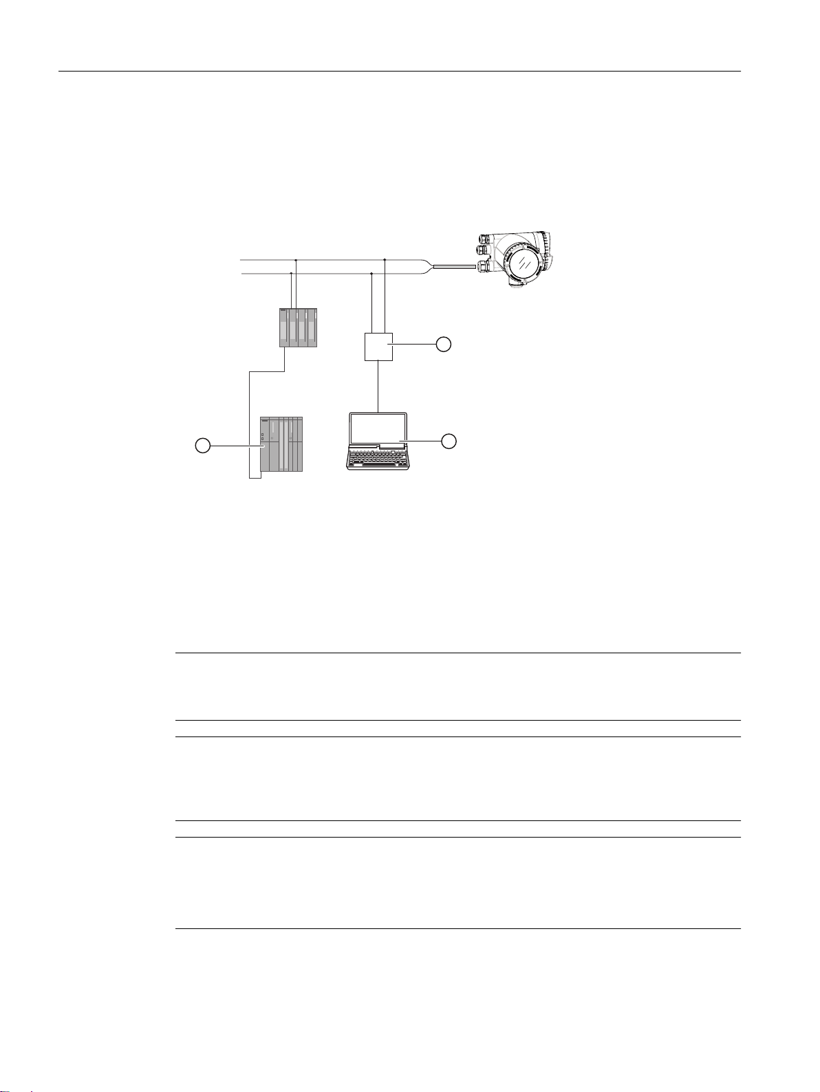
Communication is via the HART protocol, using:
● HART Communicator (load 230 to 500 Ω)
● PC with HART modem, on which appropriate software is installed, for example
SIMATIC PDM (load 230 to 500 Ω)
● Control system which can communicate via the HART protocol, for example SIMATIC PCS7
① SIMATIC PLC system with HART interface
② HART modem
③ PC with SIMATIC PDM or similar application
Figure 2-2 Possible system configurations
2.2 Connecting the Current HART, CH1
Note
4 to 20 mA output
It is not required to use shielded cables for the pure 4 to 20 mA current output.
Note
HART communication
It is recommended by the FieldComm Group (FCG) to use shielded cables for the HART
communication.
Note
Passive channels only
Channel 1 power supply must be separated from that for channels 2 to 4.
Signal return (or common) can be joined.
FCT030 HART (From firmware 4.0)
10 Function Manual, 06/2018, A5E39931617-AB
5
4
5
6
,VLJQDO
U
0
)&
Ca+
Cp-
C
8
LQW
+
-
,VLJQDO
8
H[W
8
Ca+
+
-
Cp-
)&
C
HART Communication Interface
2.2 Connecting the Current HART, CH1
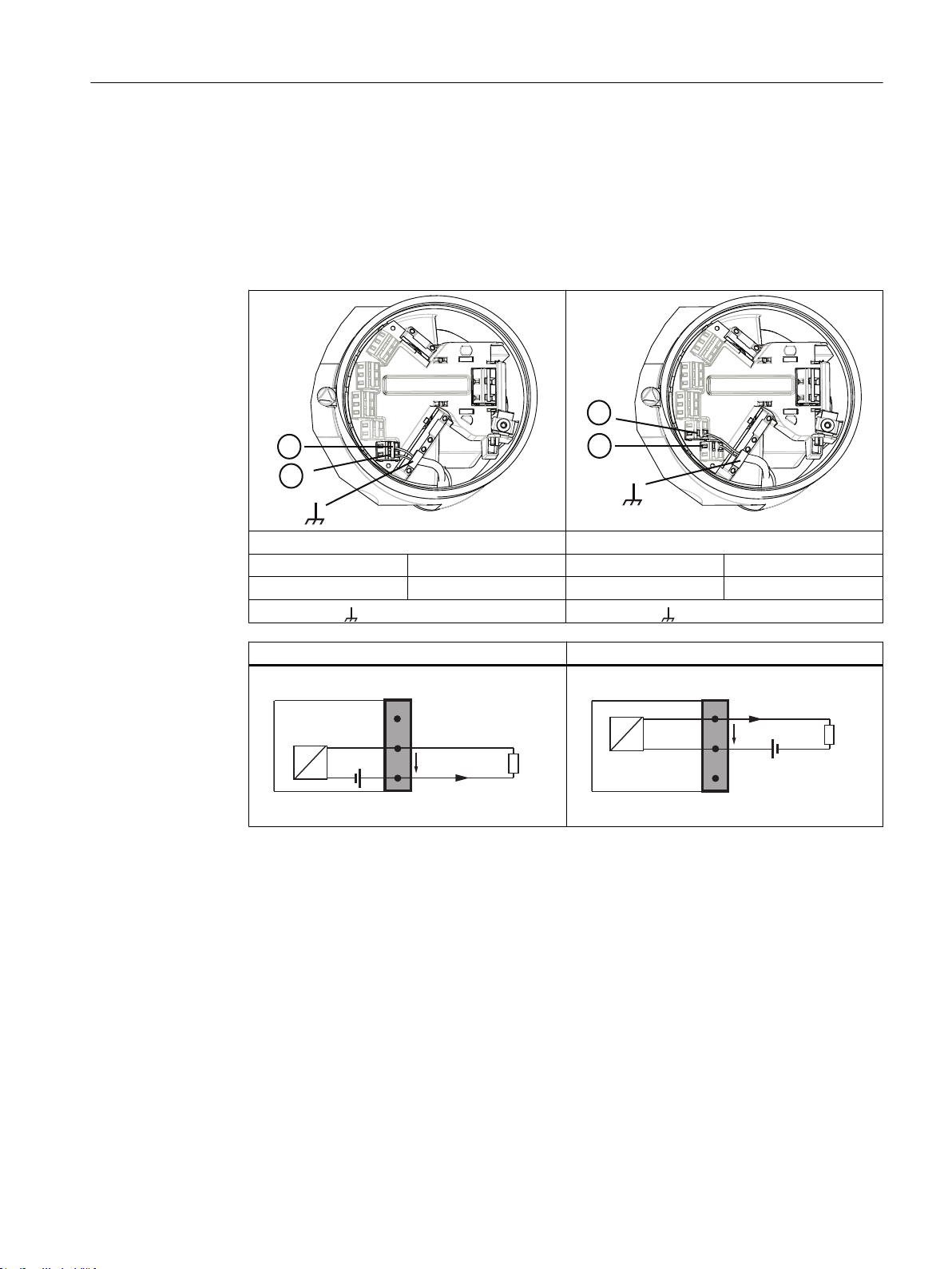
1. Remove cap and ferrule from cable gland and slide onto cable.
2. Push cable through open gland and cable path.
3. Restore ferrule and tighten cap to lightly hold cable in place.
4. Signal cable screen is folded back over outer sheath and grounded beneath cable clamp.
5. Connect wires to terminals using wiring tool, field mount transmitter
Active current output Passive current output
⑤ C ⑥ Cp-
④ Ca+ ⑤ C
Functional Earth Functional Earth
Active current output Passive current output
FCT030 HART (From firmware 4.0)
Function Manual, 06/2018, A5E39931617-AB 11
)
)
HART Communication Interface
2.2 Connecting the Current HART, CH1
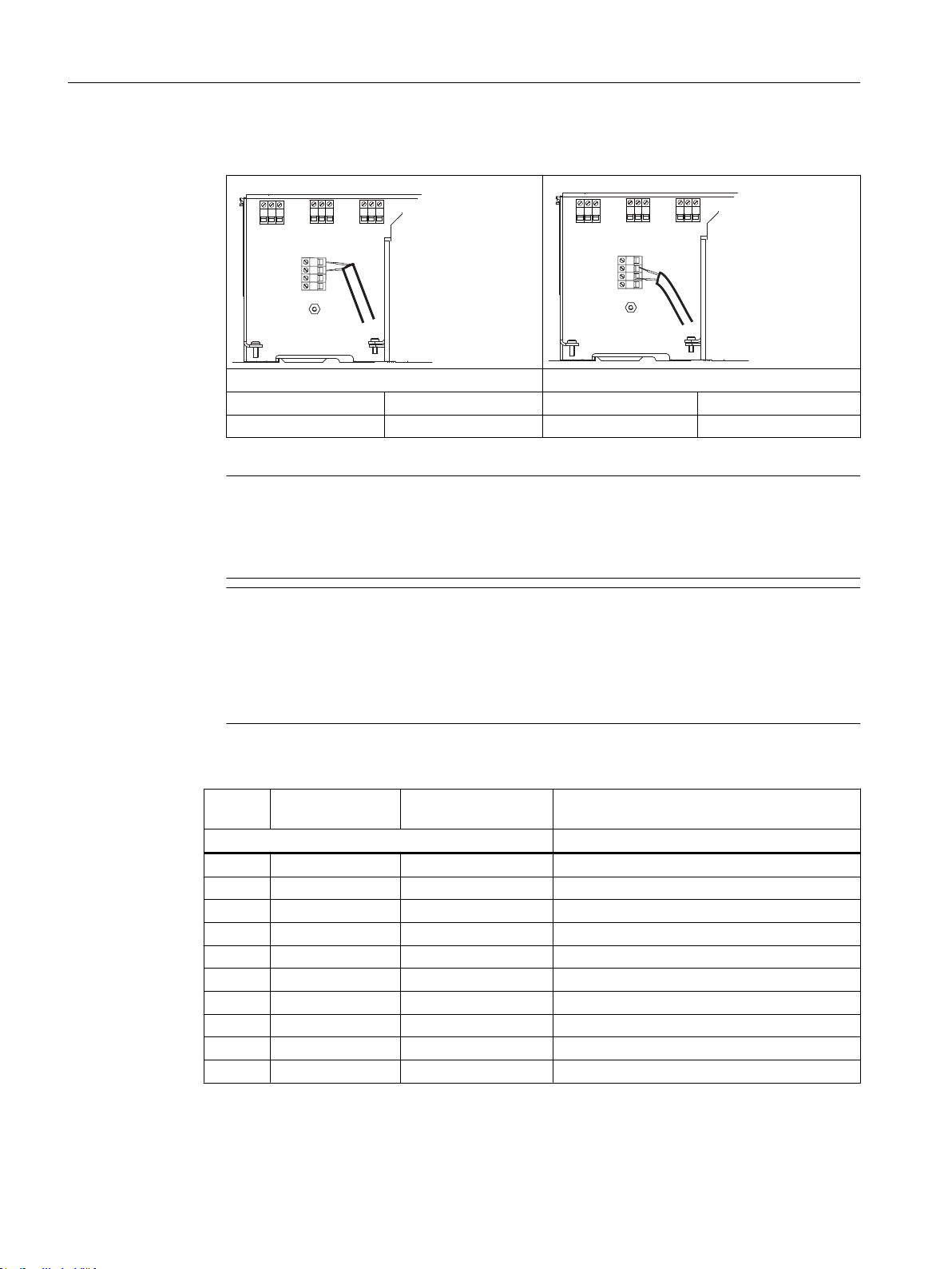
6. Connect wires to terminals, wall mount transmitter.
Active current output Passive current output
5 Ca+ 6 Cp4 C 5 C
7. Tighten cable gland.
Note
For Ex versions active or passive current output is preselected at ordering and cannot be
changed.
Non-Ex versions can be connected as either active or passive.
Note
Load
Signal output: < 500 Ω at 14 to 24 VDC (active), 14 to 30 VDC (passive)
Relay output: 30 VAC/VDC, 100 mA
Passive signal input: 15 to 30 VDC, 2 to 15 mA
Table 2-3 HW polling address
Load [Ω] Voltage (active
Ex) [V]
Measurered
100 3 3 17.7
200 5.9 5.9 19.6
500 11.4 14.9 21.0
1000 14.8 19.2 21.6
2000 17.4 20.1 21.9
5000 19.4 20.4 22.2
10000 20.3 21 22.3
20000 20 20.4 22.4
50000 20.4 20.6 22.5
100000 20.6 20.7 22.6
Voltage (active non
Ex) [V]
24 V DC Voltage supply (passive) [V] Ex and
Non Ex
FCT030 HART (From firmware 4.0)
12 Function Manual, 06/2018, A5E39931617-AB

Commissioning
3.1 General requirements
Before commissioning it must be checked that:
● The device has been installed and connected in accordance with the guidelines provided
in the Operating Instruction for FCT030 transmitter
3.2 Operating via SIMATIC PDM
SIMATIC PDM is a software package used to commission and maintain process devices.
See also
www.siemens.com/simatic-pdm. (www.siemens.com/simatic-pdm.)
3
3.3 Functions in SIMATIC PDM
SIMATIC PDM monitors the process values, alarms and status signals of the device. It allows
you to display, compare, adjust, verify, and simulate process device data; also to set schedules
for calibration and maintenance.
3.4 Commissioning steps
In the following it is described how to commission the device with SIMATIC PDM.
The steps are divided into the following sections:
1. Initial Setup (Page 14)
2. Adding device to communication network (Page 15)
3. Wizard - Quick Start via PDM (Page 18)
4. Wizard - Zero Point adjustment (Page 27)
5. Configuring a new device (Page 18)
6. I/O configuration
7. Summary
FCT030 HART (From firmware 4.0)
Function Manual, 06/2018, A5E39931617-AB 13
Commissioning
3.5 Initial Setup
3.5 Initial Setup
To ensure that SIMATIC PDM connects properly, please complete the two processes outlined
below:
1. Deactivating buffers
2. Updating the Electronic Device Description (EDD)
Deactivating buffers for RS 485 COM port
This deactivation is required to align SIMATIC PDM for Windows® operating systems.
Note
Support for Windows operating systems can be found here: support.automation.siemens.com
(http://support.automation.siemens.com)
1. Click Start → Control Panel to begin configuration.
2. Click on Hardware and Sound and then on Device Manager.
3. Open Ports folder and double-click the COM Port used by the system to open the
Communications Port Properties window.
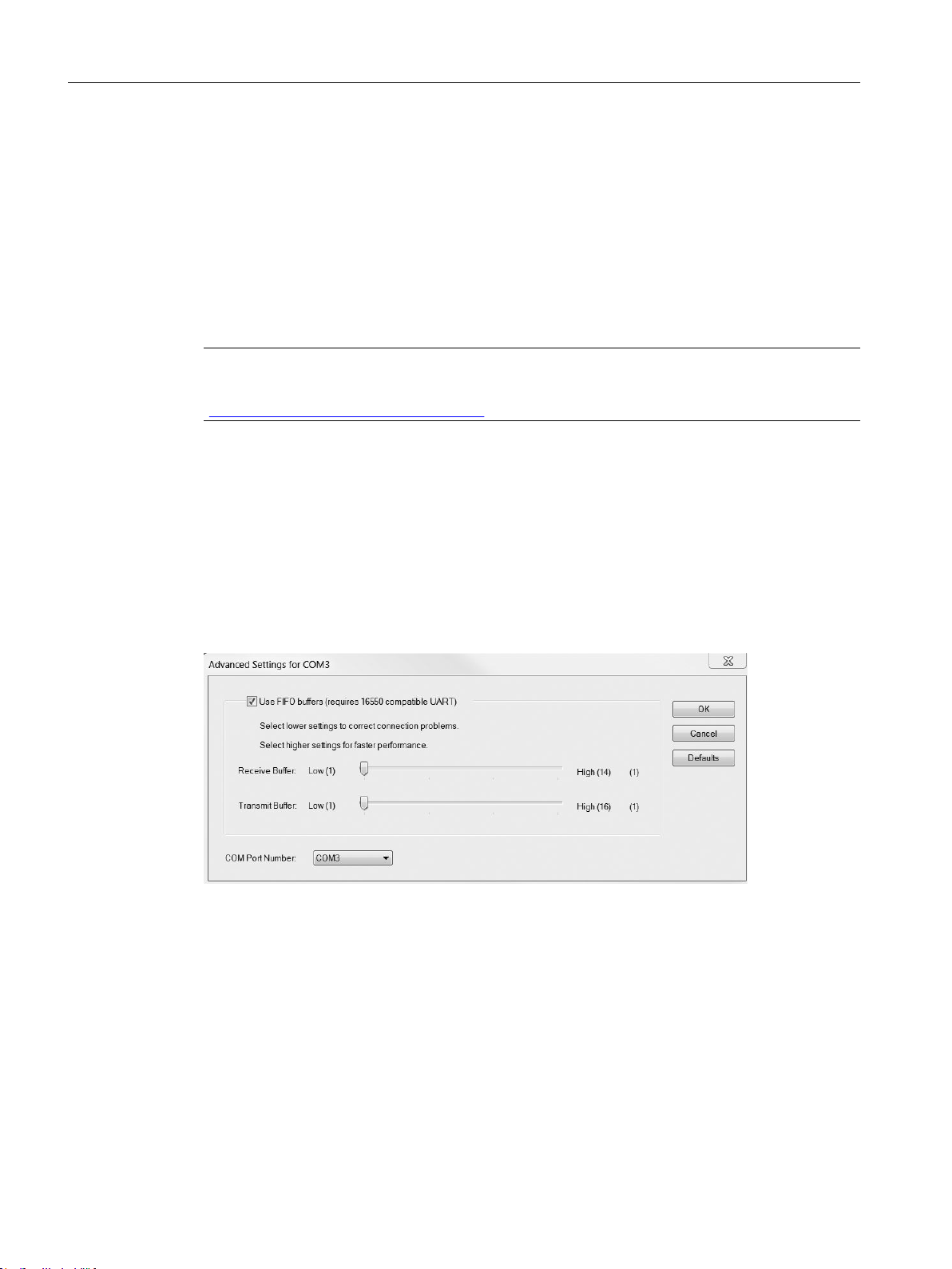
4. Select the Port Settings tab and click the Advanced button.
5. If the Use FIFO buffers check box is deselected, click to select.
6. Set Receiver Buffer and Transmitter Buffer to Low (1).
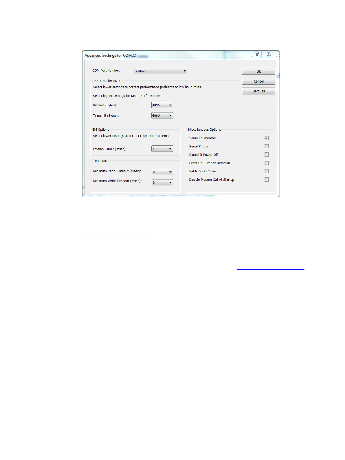
Figure 3-1 COM Port Setting
For serial adapters it can be required to change the Latency Timer (msec) to 1
FCT030 HART (From firmware 4.0)
14 Function Manual, 06/2018, A5E39931617-AB
Commissioning
3.6 Adding device to communication network
See also
Updating the Electronic Device Description (EDD)
You can locate the EDD in the SIMATIC PDM Device Library under Devices → HART → Sensors
→ Flow → Coriolis → Siemens AG → SITRANS FC430. Check the product page of our website
(www.siemens.com/FC430) under Support > Software downloads, to make sure you have the
latest version of SIMATIC PDM, the most recent Service Pack (SP) and the most recent hot
fix (HF).
Installing a new EDD:
1. Download the EDD from the product page of our website (www.siemens.com/FC430) and
save the files to your computer.
2. Launch the SIMATIC PDM Device Integration Manager, browse to the EDD file and select
it.
3. Select the check boxes for the devices whose device descriptions are to be integrated. The
check box is automatically selected for devices that have not been integrated or have been
integrated with an older version. You can work with a split device list window.
4. Select Catalog → Integration. The device descriptions are transferred to the PC.
Commissioning steps (Page 13)
Wizard - Quick Start via PDM (Page 18)
3.6 Adding device to communication network
Before setting the parameters, it is necessary to configure the FC430 project in PDM.
FCT030 HART (From firmware 4.0)
Function Manual, 06/2018, A5E39931617-AB 15
Commissioning
3.6 Adding device to communication network
1. Add the device to SIMATIC HART network:
– Select File → New. Type in a project name, for example FC430 commissioning.
– Go to View and select Process Device Network view.
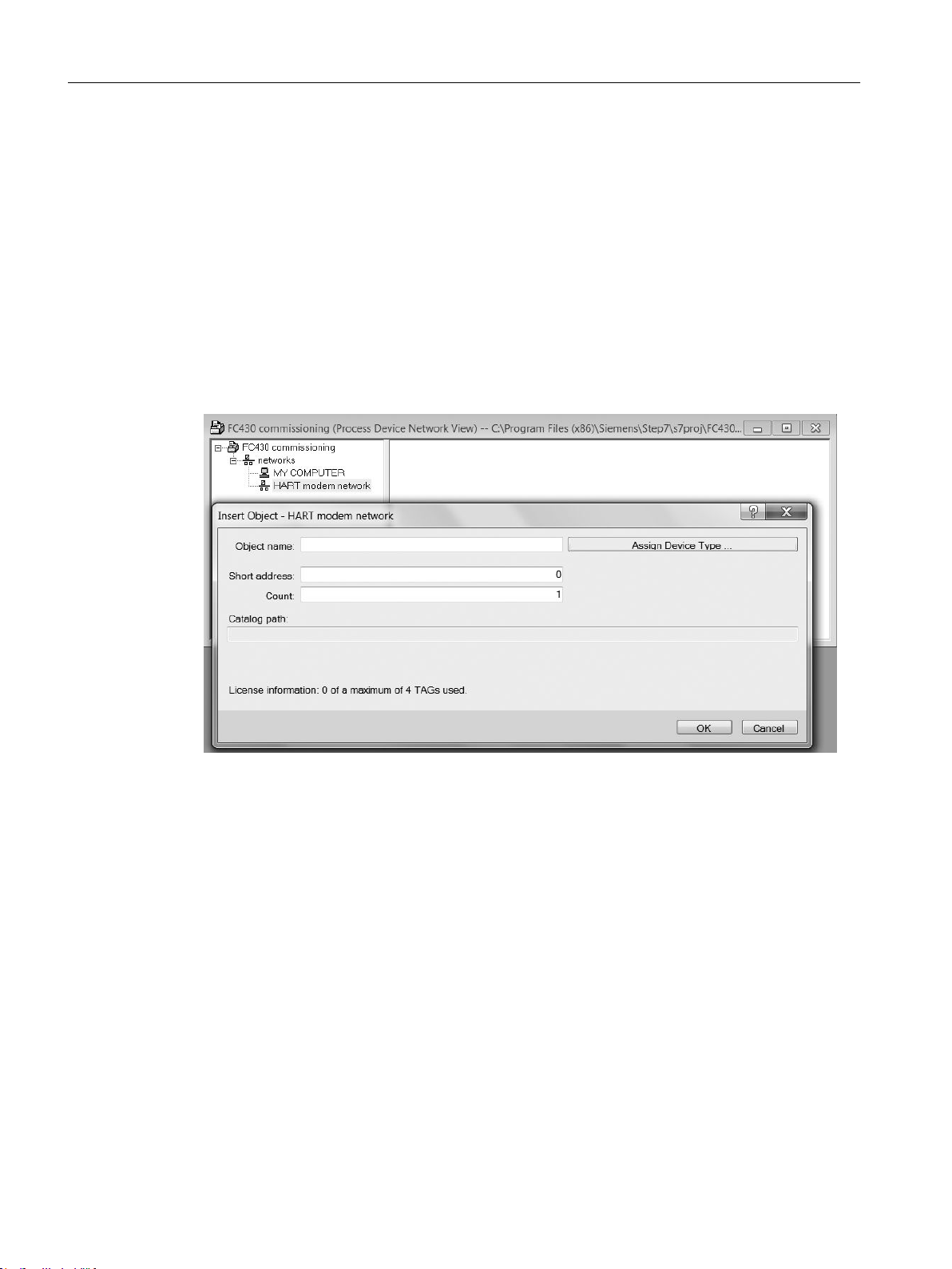
– Right-click on the typed in Project name and select Insert New Object → Networks.
– Right-click on Networks and Insert New Object → Communication Network.
– Click on Assign Device Type and select HART Modem Network. Click OK two times. Your
PC is now added to the HART Modem Network.
– Right-click on HART Modem Network and select Insert New Object → Object.
– Click on Assign Device Type, and select Devices → HART → Sensors → Flow → Coriolis →
SIEMENS AG → SITRANS FC430 Click OK two times.
Figure 3-2 Assigning a HART modem network
2. Set up the communication parameters for SIMATIC HART modem network:
– Select Networks → My computer, right-click on COM Port Interface and select Object
Properties.
– Select the Communication tab and configure the communication parameters.
FCT030 HART (From firmware 4.0)
16 Function Manual, 06/2018, A5E39931617-AB
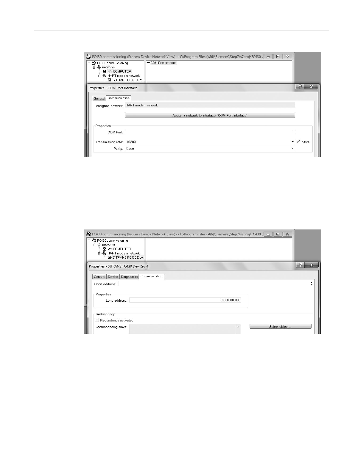
Figure 3-3 HART modem properties
– Click OK.
3. Set up the HART address:
– Select HART modem network.
Commissioning
3.6 Adding device to communication network
– Right-click on the object name SITRANS FC430 and select Object Properties.
– Select the Communication tab and configure the HART address.
Figure 3-4 Set the HART address
– Click OK.
FCT030 HART (From firmware 4.0)
Function Manual, 06/2018, A5E39931617-AB 17

Commissioning
3.8 Wizard - Quick Start via PDM
3.7 Configuring a new device
Note
Clicking on "Cancel" during an upload from device to SIMATIC PDM will result in some
parameters NOT being updated.
1. Check that you have the most recent EDD, and if necessary update it, see "Updating the
Electronic Device Description (EDD)" in Initial Setup (Page 14).
2. Launch SIMATIC Manager.
3. Right-click on SITRANS FC430 and select Open Object to open SIMATIC PDM.
4. Click on the device and select Upload to the PG/PC to upload the configuration from he
device.
3.8 Wizard - Quick Start via PDM
The graphic Quick Start Wizard provides an easy 7-step procedure that configures the device
for a simple application.
Please consult the SIMATIC PDM operating instructions or online help for details on using
SIMATIC PDM.
Access level control
Some parameters are protected against changes by access level control. To gain access,
select Access Management from the device menu, select User or Expert mode and enter the
PIN code.
● User
Allows configuration and service of all parameters except calibration parameters. Default PIN
code is 2457.
● Expert
Allows configuration and service of all parameters including flow and density adjustment
parameters. Default PIN code is 2834.
Quick start
Note
● The Quick Start wizard settings are inter-related and changes apply only after you click on
● Do not use the Quick Start Wizard to modify individual parameters.
● Click on "Back" to return and revise settings or "Cancel" to exit the Quick Start.
"Apply" at the wizard to transfer settings to save settings offline and transfer them to the
device.
FCT030 HART (From firmware 4.0)
18 Function Manual, 06/2018, A5E39931617-AB

Commissioning
3.8 Wizard - Quick Start via PDM
Launch SIMATIC PDM, open the menu "Device – Wizard - Quick Start", and follow steps.
Figure 3-5 Wizard Quick Start
Step 1 - Identification
Note
The layout of the dialog boxes shown may vary according to the resolution setting for your
computer monitor. The recommended resolution is 1280 x 960.
1. The parameter settings are read from device automatically so the Quick Start wizard starts
with the values stored in device.
FCT030 HART (From firmware 4.0)
Function Manual, 06/2018, A5E39931617-AB 19
Commissioning
3.8 Wizard - Quick Start via PDM
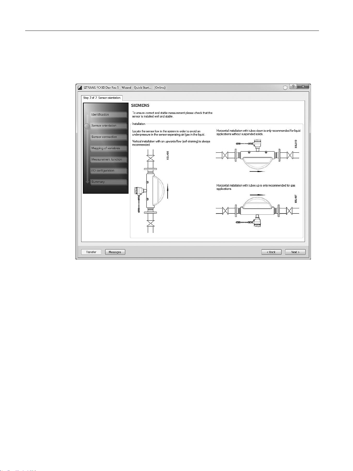
Step 2 - Sensor orientation
Step 2 shows an overview of the various recommended installation orientations depending on
the application.
Figure 3-6 Quick start step 2
FCT030 HART (From firmware 4.0)
20 Function Manual, 06/2018, A5E39931617-AB
 Loading...