

Siemens SITRANS F M MAGFLO series, SITRANS F C MASSFLO series Operating Manual

[]
Operating Manual
Order no.: FDK:521H1183
SFIDK.PS.023.D2.02 - A5E00253376
s
SITRANS F M MAGFLO
&
SITRANS F C MASSFLO
Modbus RTU RS-485 add-on module
for USM II transmitters

Modbus RTU RS-485
2
SFIDK.PS.023.D2.02
Contents 1. Introduction .................................................................................................................... 3
1.1 Definitions and Abbreviations ........................................................................................ 3
1.2 References ..................................................................................................................... 3
2. Technical data ................................................................................................................4
2.1 General Modbus RTU .................................................................................................... 5
3. Installation ...................................................................................................................... 6
3.1 Add-on module .............................................................................................................. 6
3.2 General electrical information ........................................................................................ 7
3.3 USM II connections ........................................................................................................ 7
3.4 RS-485 termination ........................................................................................................ 7
3.4.1 RS-485 cabling .............................................................................................................. 7
4. Commissioning .............................................................................................................. 8
4.1 Effect of changing Modbus communication settings ..................................................... 8
4.2 Modbus RTU display menu ........................................................................................... 9
4.3 Menu item explanation ................................................................................................ 10
5. Modbus addressing model .......................................................................................... 11
5.1 Modbus function codes ................................................................................................ 11
6. Modbus holding registers ............................................................................................ 13
6.1 Process data ................................................................................................................ 14
6.2 Modbus driver settings ................................................................................................. 14
6.3 Modbus application settings ........................................................................................ 15
6.4 Basic settings ...............................................................................................................16
6.5 Totalizer ........................................................................................................................ 17
6.6 Output ........................................................................................................................... 17
6.7 External input ...............................................................................................................21
6.8 Sensor characteristics .................................................................................................. 21
6.9 Product identity ............................................................................................................ 22
6.10 Service info .................................................................................................................. 22
6.11 Display settings ............................................................................................................ 23
6.12 Flowmeter status .......................................................................................................... 25
7. Modbus coils ................................................................................................................ 26
7.1 Communication settings .............................................................................................. 26
7.2 Auto zero adjust ........................................................................................................... 26
7.3 Totalizer ........................................................................................................................ 26
7.4 Batch ............................................................................................................................ 26
APPENDIX A - SI-units used in USM II products ...................................................................... 27
APPENDIX B - USM II Error Pending and Error Log ................................................................ 27
APPENDIX C - Modbus communication examples ................................................................. 28
APPENDIX D - CRC calculation .............................................................................................. 31
APPENDIX E - Exception codes .............................................................................................. 33
APPENDIX F - Run Indicator .................................................................................................... 33
APPENDIX G - Units and Point positions ................................................................................. 34
APPENDIX H - Float Definition ................................................................................................. 35

Modbus RTU RS-485
3
SFIDK.PS.023.D2.02
This manual is intended to provide instructions for the installation and use of the Modbus RTU
add-on module, product code number FDK:085U0234, that can be used in the Siemens Flow
Instruments USM II family of transmitters, which presently includes MAG 6000 and MASS 6000.
The Modbus RTU module is effectively a gateway through which a Modbus RTU master device
can have controlled access to a number of Siemens Flow Instruments USM II signal converter
parameters.
This manual is not intended to be a complete tutorial on the Modbus RTU protocol, and it is
assumed the end user already has a general working knowledge of Modbus RTU communications, especially in respect of master station configuration and operation. However an overview
is included in the following section to explain some of the fundamental aspects of the protocol.
1. Introduction
1. Introduction
1.1 Definitions and
Abbreviations
CRC Cyclic Redundancy Check
Used for error-checking in Modbus RTU. See appendix
Modbus master A Modbus device, which is able to access data in one or more
connected Modbus slaves
Modbus slave A Modbus device, which is able to respond to requests from a single
Modbus master
Modbus address Throughout this document the following notation is used to address
Modbus RTU registers and coils:
1:123
Coil number 123 (addressed in messages by 122)
4:1234
Holding register 1234 (addressed in messages by 1233)
4:54321
Holding register 54321 (addressed in messages by 54320)
34567
The address of a coil/holding register as specified in a
message
RS-485 Refers to the 2-wire communication standard defined by EIA/TIA-485.
(Physical layer)
RTU Remote Terminal Unit = Standard Modbus transmission mode
1.2 References
Reference 1 Modbus over Serial Line
Specification & Implementation guide v. 1.0
modbus.org 12/02/02
Reference 2 Modbus Application Protocol Specification
v. 1.1
modbus.org 12/06/02

Modbus RTU RS-485
4
SFIDK.PS.023.D2.02
2. Technical data
Siemens Flow Instruments Modbus RTU specification
Device type Slave
Baud rates 1200, 2400, 4800, 9600, 19200, 38400, 57600,
76800, 115200 bits/sec.
Number of stations Recommended: max. 31 per segment without repeaters
Device address range 1-247
Protocol RTU
(Other Modbus protocols like ASCII, Plus or TCP/IP are not supported)
Electrical interface RS-485, 2 wire
Connecter type Screw terminals
Supported function codes 1 read coils
3 read holding registers
5 write single coil
16 write multiple registers
17 report slave ID
Broadcast No*)
Maximum cable length 1200 meters (@115200 bits/sec.)
Standard Modbus over serial line v1.0*)
Certified No
Device profile None
*) Standard restriction
The standard requires a LED indicator for visual diagnosis. This module do not support a LED indicator.
Instead comprehensive display information is available. This device does not react to any Broadcast
commands.
2. Technical data
Modbus RTU RS-485
5
SFIDK.PS.023.D2.02
The module complies with the Modbus serial line protocol [Reference 1].
Among other things this implies a master-slave protocol at level 2 of the OSI model. One node
(the master) issues explicit commands to one of the „slave“-nodes and processes responses.
Slave nodes will not transmit data without a request from the master node, and do not
communicate with other slaves.
Modbus is a mono master system, which means that only one master can be connected at the
time.
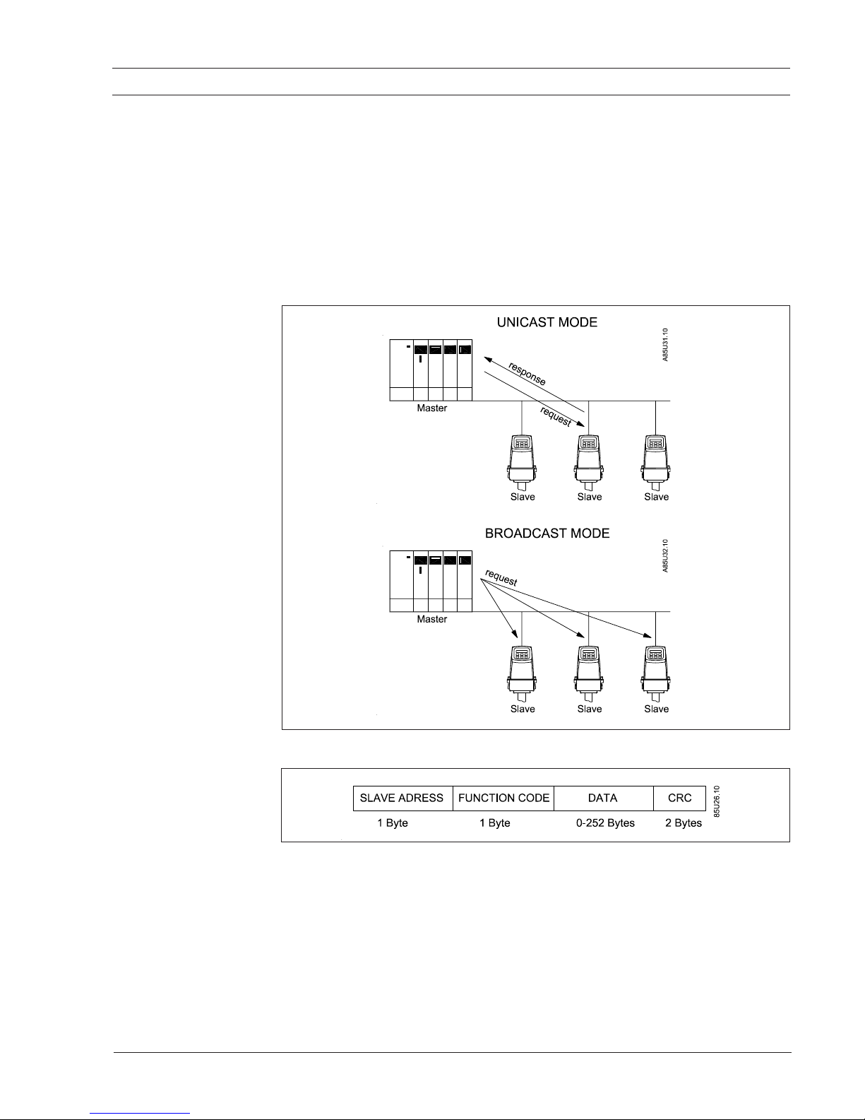
Two modes of communication are possible, Unicast and Broadcast. Unicast mode is where the
master sends a request to one slave device, and waits a specified time for a response. In
Broadcast mode the master sends out a request to address „0“, which means that the information
is for all slave devices on the network. In Broadcast mode there are no response from the slave
devices.
2.1 General Modbus RTU
The Modbus frame is shown below, and is valid for both requests and responses.
Further details of the Modbus protocol can be found in Reference 1 and 2.
2. Technical data
Modbus RTU RS-485
6
SFIDK.PS.023.D2.02
3. Installation
3. Installation
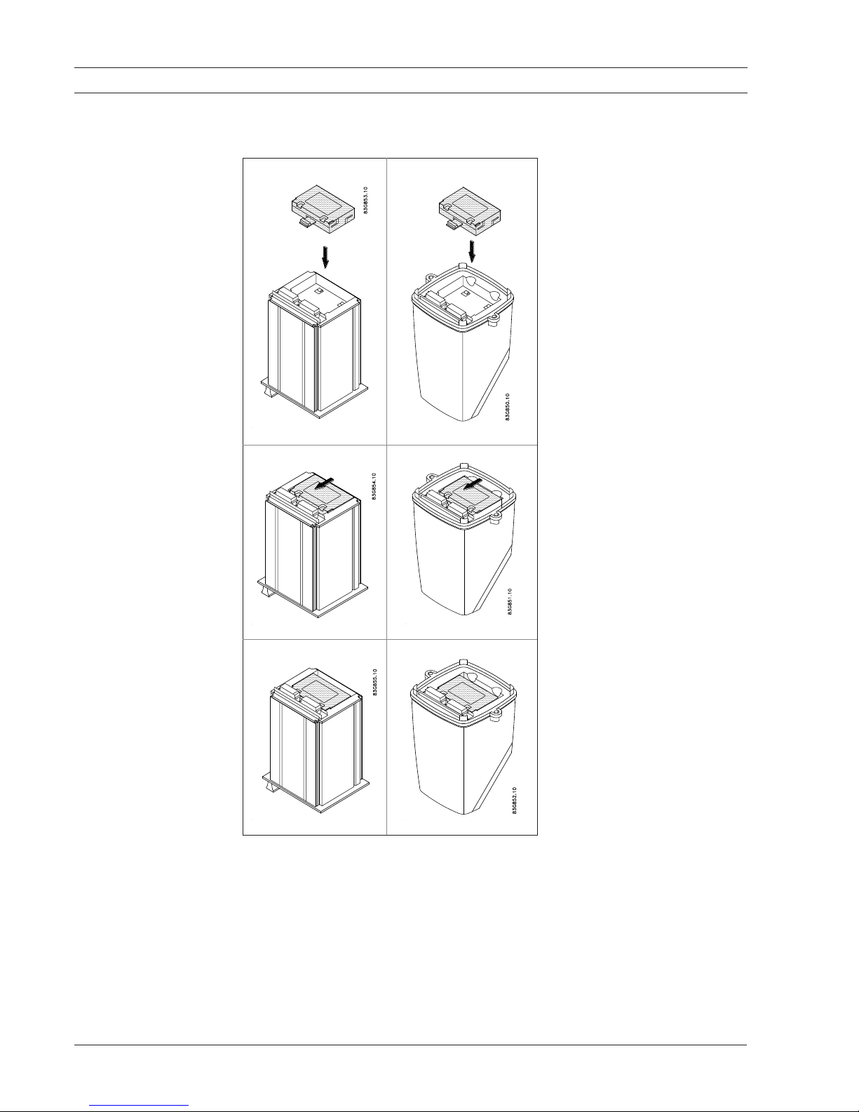
3.1 Add-on module
19” rack mounted versions IP 67 compact versions
The installation procedure for an add-on module to a Siemens Flow Instruments USM II
transmitter is as follows:
1. Unpack the add-on module and
insert it in the bottom of the signal
converter as shown.
2. Press the add-on module in the
direction shown, until it stops and
is firmly seated in position
3. This completes the add-on module installation, and the signal
converter may now be connected
to the terminal box. Communication with the display/keypad and
the electrical input/output terminals is established automatically
when the power is applied.
Modbus RTU RS-485
7
SFIDK.PS.023.D2.02
3. Installation
3.2 General electrical
information
On the electrical termination boards for USM II transmitters, additional input/output terminals have
been reserved for add-on module functions. The numbering range of these terminals is as follows,
but how many are actually used depends on the type of add-on module. Please refer to the
relevant handbook for other electrical connection information.
Terminals reserved for add-on modules:
MAG 6000: 91 - 97
MASS 6000: 91 - 100
Note
The standard inputs and outputs continue to function and are not affected by the presence of an
add-on module. It is however not possible to install this module in a MASS 6000 with extra outputs.
If a Current Out 2 is present, the MASS 6000 has extra outputs installed.
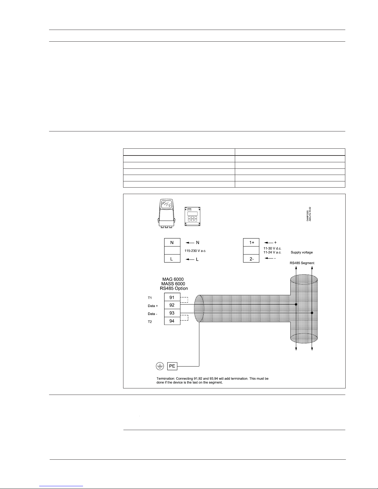
3.3 USM II connections
The following table shows the connection layout for the USM II Modbus RTU module:
Terminal number Modbus RTU RS-485 connection
91 T1
92 Data +
93 Data −
94 T2
PE Shield
3.4 RS-485 termination All RS-485 based networks must be terminated correct to function properly. A termination must
be placed at each end of the segment.
The Modbus RTU module can add a termination by connecting terminals 91 to 92 and 93 to 94.
It is important to use very short wires for this connection.
3.4.1 RS-485 cabling To ensure error free operation, a good quality cable meeting the RS-485 specifications, must be
used.

Modbus RTU RS-485
8
SFIDK.PS.023.D2.02
4. Commissioning
4. Commissioning
Before communicating with the master, baudrate, node ID and update rate must be selected. This
can be done from the display. Please look in to the transmitter manual to locate the Modbus RTU
menu.
4.1 Effect of changing
Modbus communication settings
Changing baudrate or framing has effect on the communication as follows:
• When changed from the menusystem, new settings have effect immediately.
(Same effect as writing to the „ResetCommunication“ coil).
• When changed from the Modbus master, the new settings only have effect after a reset
(PowerUp) of the module - or after writing to the „ResetCommunication“ coil.
In both cases the new settings will not have effect until the Modbus driver has responded to any
ongoing Modbus request.
Note
It is recommended NOT to use the default address in a
multi-slave network
.
It is of great importance to ensure at the time of the procedure of device addressing, that there
is not two devices with the same address. In such a case, an abnormal behaviour of the whole
serial bus can occur, the master being then in the impossibility to communicate with all present
slaves on the bus.
Modbus RTU RS-485
9
SFIDK.PS.023.D2.02
4. Commissioning
4.2 Modbus RTU display
menu
To change (or view) the Modbus RTU settings from the keypad display.
1. Press [Top key] for two seconds. (Note: For “View” mode only, skip steps 2 & 3).
2. Type in password (1000) by pressing [Change key] two times, and then press
[Lock key] and hold for two seconds
3. The display now says “Basic settings”
4. Press [Forward key] until you reach the “Modbus RTU module” menu item
5. Press [Lock key]
6. You can now cycle through all the Modbus RTU settings by pressing [Forward key]
7. Press [Top key] for two seconds and you return to 1.

Modbus RTU RS-485
10
SFIDK.PS.023.D2.02
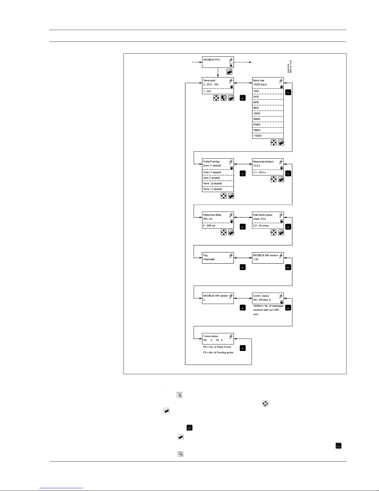
4.3 Menu item
explanation
4. Commissioning
Item Value Comments
Slave addr. 1-247 Device address
[Factory setting: 1]
Baud rate 1200, 2400, 4800, 9600, Communication speed
[Factory setting: 19200]
19200, 38400, 57600,
76800, 115200
Parity/framing Even, 1 stopbit Communication parameters
Odd, 1 stopbit
[Factory setting: Even, 1 stopbit]
None, 2 stopbit
None, 1 stopbit
Response timeout 0-25,5 sec. Max. response time. Used in time critical applica-
tions, where low cycle times are required. If the
response is not ready within the „Response
Timeout“ time, an exception code 6 (Busy acknowledge) is returned and the request must be send
again.
[Factory setting: 10,0]
Response delay 0-255 msec. The minimum time from when a slave receives a
request and until it returns a response. This makes
it possible to send data to slow masters without
overwhelming its receiver.
[Factory setting: 0]
Interframe spacing 3,5-25 chars The minimum interframe space between two
Modbus RTU messages in sequence (specified as
3.5 characters) is configurable.
Range: 3.5 - 25 character times.
[Factory setting: 3,5]
TAG „Flowmeter“ The TAG can be changed to any string up to
16 chars.
[Factory setting: Flowmeter]
Modbus SW version 1.00 Firmware version of the Modbus module
Modbus HW version 2 Hardware version of the Modbus module
Comm. status Ok: xx Ok = Received messages without errors
Bad: xx Bad = Received messages with CRC errors
Reset after a power down
Frame status PE: xx PE = Number of parity errors
FE: xx FE = Number of framing errors
Reset after a power down
The settings are all stored in the non-volatile memory of the SENSORPROM unit, and therefore
remembered after a power down. Even if the module or transmitter is replaced the settings are
kept.
If the SENSORPROM
unit is NOT used, then the settings are stored in the transmitters memory.
These settings will however be overruled if the SENSORPROM unit is used again.

Modbus RTU RS-485
11
SFIDK.PS.023.D2.02
5. Modbus addressing model
5. Modbus addressing
model
The module allows R/W access to the following standard Modbus data register blocks:
• Coils (ref. 0x address range)
• Holding registers (ref. 4x address range)
I.e. the module will not support the other standard data register blocks:
• „Discrete input“ (ref. 1x address range)
• „Input registers“ (ref. 3x address range)
5.1 Modbus function codes
This device supports following function codes: 1, 3, 5, 16 and 17.
Function code 1 and 5 are used for accessing coils. 3 and 16 are used for accessing registers.
Function code 17 (report slave ID) will return a structure of identification information of the device.
Below the different function code exceptions are described.
Function code 1 (Read coils)
General exceptions:
• Requesting less than 1 or more than 2000 coils => Exception 3 (Illegal data value)
• Requesting more than max. message size (440 coils) => Exception 2 (Illegal data address)
• Requesting data above/crossing limitation of max. coil address (0xFFFF) => Exception 2
(Illegal data address)
Application exceptions:
• Application errors => Exception 4 (Slave device error)
• Further information about the error can be read from holding registers 680+681 (Last Coil
Addr + ErrorNo)
Holes/register alignment:
• Unmapped coils return zero when read
Function code 3 (Read holding registers)
General exceptions:
• Requesting less than 1 or more than 125 registers => Exception 3 (Illegal data value)
• Requesting more than max. message size (27 registers) => Exception 2 (Illegal data address)
• Requesting data above/crossing limitation of max. register address (0xFFFF) => Exception
2 (Illegal data address)
Application exceptions:
• Application errors => Exception 4 (Slave device error)
• Further information about the error can be read from holding registers 682+683 (Last
HoldReg Addr + ErrorNo)
Holes/register alignment:
• The read command always returns data if no exception is given. Bad start/end alignment will
result in only parts of the data item being read
• Holes in the holding register map return value zero in all bytes. E.g. reading 2 registers starting
at 4:0004 above will result in 2 bytes of „float B“ followed by 2 zeroes
Function code 5 (Write single coil)
General exceptions:
• Writing anything else but 0x0000 (OFF) or 0xFF00 (ON) to a coil => Exception 3 (Illegal data
value)
• Writing to an unmapped coil => Exception 2 (Illegal data address)
Application exceptions:
• Application errors => Exception 4 (Slave device error)
• Further information about the error can be read from holding registers 680+681 (Last Coil
Addr + ErrorNo)
 Loading...