

Siemens SITRANS F C MASSFLO MASS 2100 DI 25, SITRANS F C MASSFLO MASS 2100 DI 6, SITRANS F C MASSFLO MASS 6000 Ex-d, SITRANS F C MASSFLO MASS 2100 DI 40, SITRANS F C MASSFLO MASS 2100 DI 3 User Manual
...
Manual
Order no.: FDK:521H1178
SFIDK.PS.028.Q1.02 - A5E00253712
SITRANS F C MASSFLO
MASS flowmeters
Signal converter type MASS 6000 Ex-d
sensor type MASS 2100
compact or remote mounted
[]
*083R9506*
s
SITRANS F C MASSFLO
2
SFIDK.PS.028.Q1.02
Contents
1. Introduction ..................................................................................................................................... 2
2. Installation ....................................................................................................................................... 3
2.1 Compact ............................................................................................................................................ 3
2.2 Remote ............................................................................................................................................. 3
2.3 Ex survey according to Directive 94/9/EC (ATEX) ........................................................................... 4
2.4 Overview ........................................................................................................................................... 5
2.5 Device identification .......................................................................................................................... 6
2.6 Approvals .......................................................................................................................................... 7
2.7 Special conditions for safe use of MASS 6000 Ex-d version and MASS 2100 ............................... 7
2.8 Mounting of signal converter compact or remote ............................................................................. 8
2.9 Display and keypad .......................................................................................................................... 8
3. Electrical connection ..................................................................................................................... 9
3.1 Electrical connection compact or remote ......................................................................................... 9
3.2 Setting of active or passive current out-put mode ........................................................................... 11
3.3 SENSORPROM unit ...................................................................................................................... 11
3.4 Installation of add-on module (AOM) ............................................................................................. 12
3.5 Installation examples ...................................................................................................................... 13
4. Technical data ............................................................................................................................... 14
4.1 Sensor MASS 2100. Versions DI 1.5, DI 3, DI 6, DI 15, DI 25, DI 40 ........................................... 14
4.2 Signal converter MASS 6000 Ex-d ................................................................................................. 15
4.3 Output characteristic MASS 6000 .................................................................................................. 17
5. Commissioning ............................................................................................................................. 18
5.1 Keypad and display layout .............................................................................................................. 18
5.2 Menu build-up ................................................................................................................................. 19
5.2.1 Password ........................................................................................................................................ 19
5.3 Menu overview ................................................................................................................................ 20
5.4 Menu details ................................................................................................................................... 21
5.5 Outputs setting menu ..................................................................................................................... 22
5.6 Reset mode .................................................................................................................................... 24
6. Service ........................................................................................................................................... 25
6.1 List of error numbers ...................................................................................................................... 25
6.2 Trouble shooting MASS 6000 ......................................................................................................... 26
7. Ordering ......................................................................................................................................... 27
7.1 Build-up ordering ............................................................................................................................ 27
7.2 Build-up ordering - High pressure versions .................................................................................... 28
7.3 Signal converter MASS 6000 Ex-d for remote mounting ............................................................... 29
7.4 Accessories for MASS 6000 Ex-d and MASS 2100 ....................................................................... 29
8. Certificates .................................................................................................................................... 30
8.0 Download certificates ..................................................................................................................... 30
8.1 EU-declaration of conformity ......................................................................................................... 30
8.2 EC type examination certificate ...................................................................................................... 31
1. Introduction
For safety reasons it is important that the following points, especially the points marked with
a warning sign, are read and understood before the system is being installed:
• Installation, connection, commissioning and service must be carried out by personnel
who are qualified and authorized to do so.
• It is very important that the same people have read and understand the instructions and
directions provided in this manual and that they follow the instructions and directions
before taking the equipment into use!
• People who are authorized and trained by the owner of the equipment may operate the
equipment.
• The installation must ensure that the measuring system is correctly connected and is
in accordance with the connection diagram. The signal converter has to be earthed
unless the power supply is galvanically isolated.
• In applications with working pressures/media that can be dangerous to people,
surroundings, equipment or others in case of pipe fracture, we recommend that special
precautions such as special placement, shielding or installation of a security guard or
a security valve should be made when the sensor is being installed.
• Siemens Flow Instruments want to assist by estimating the chemical resistance of the
sensor parts that are in connection with the media, but it is at any time the customer’s
responsibility, which materials are chosen and Siemens Flow Instruments takes no
responsibility if the sensor corrodes!
It is required that the special directions provided in the manual and in the Ex certificate
must be followed!
• Installation of the equipment must comply with national regulations.
Example EN 60079-14 for Denmark.
• Repair and service can be done by approved Siemens Flow Instruments personnel only.
- this page has been updated 2004.01
SITRANS F C MASSFLO
3
SFIDK.PS.028.Q1.02
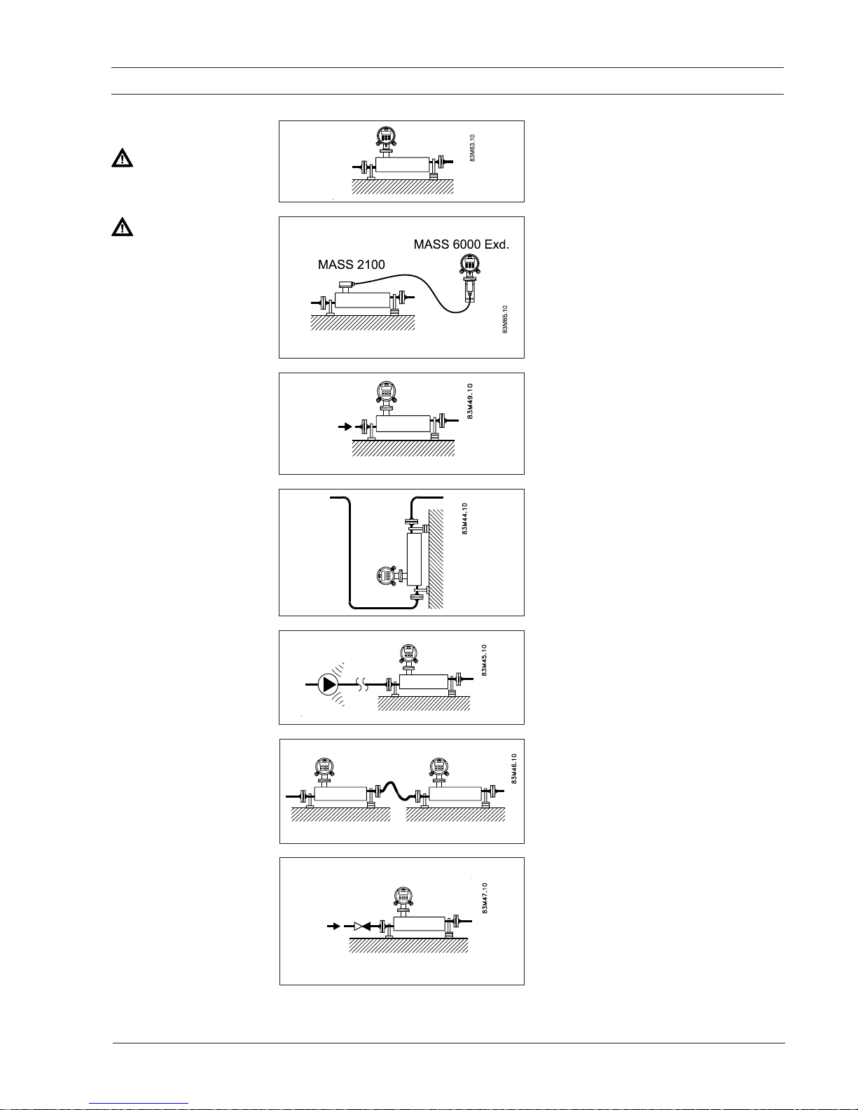
Mount the sensor on a vibration-free wall or
steel frame as shown.
Ensure that the sensor is not emptied of liquid
(during normal operation) otherwise incorrect
measurement will occur.
With low flow, horizontal mounting is recommended, in this position air bubbles are
easier to remove.
Locate the sensor low in the system in order to
avoid an under-pressure in the sensor seperating air/gas in the liquid.
If the liquid is volatile or contains solid
particles, vertical mounting is not recommended.
Always locate the flowmeter as far away as
possible from components that generate mechanical vibration in the piping.
Cross talk between sensors mounted close to
each other may disturb the measurement. To
avoid cross talk never mount more than one
sensor on each frame and mount flexible hose
connections between the sensors as shown.
2. Installation
Vertical mounting
Vibration
Cross talk
2. Installation
To facilitiate zero-point adjustment, a valve with
tight shut-off should always be mounted in connection with the sensor as a proper zero-point
setting is essential for a good accuarcy.
Note
Please read and follow the directions stated in
the instruction DKFD.PI.028.P1.52 regarding
build-in of sensor.
The instruction is supplied with the sensor.
Zero-point adjustment
Horizontal mounting
Category 2 equipment
May be installed in zone 1 and zone 2.
Category 1 equipment
Sensor MASS 2100 may be installed in zone 0,
zone 1 and zone 2.
Catetory 2 equipment
Signal converter MASS 6000 Ex-d may only be
installed in zone 1 and zone 2.
2.1 Compact
2.2 Remote
SITRANS F C MASSFLO
4
SFIDK.PS.028.Q1.02
2. Installation
2.3 Ex survey according
to Directive 94/9/EC
(ATEX)
Applies to instruments used in underground mining
operations, as well as their above ground
operations, which can be endangered by mine gas
and/or flammable dusts.
Instrument groups
Applies to instruments used in the remaining areas
which can be endangered by a potentially explosive
atmosphere.
Instruments of this category are for use in areas
where ignitable atmospheres caused, by a
mixture of air and gasses, vapours or mists or by
dust/air mixtures, can exist all of the time or for
long periods of time or else frequently.
Instruments of this category are for use in areas
where ignitable atmospheres caused, by a
mixture of air and gasses, vapours or mists or by
dust/air mixtures, can exist some of the time.
Instruments of this category are for use in areas
where ignitable atmospheres caused, by a
mixture of air and gasses, vapours or mists or by
dust/air mixtures, are not likely to exist. However,
if they do occur then in all probability, only
seldom or for short periods of time.
Instrument category
(The figures in brackets refer to IEC)
Built according to European norm = E
Explosion protected electrial equipment = Ex
Ex protection labelling in square brackets refers to "Associated electrical equipment"
as an example
:
II 2G E Ex ia IIC T6
Type of protection
o Oil encapsulated i Intrinsic safety (ia, ib)
p Pressurized apparatus n Non-incentive equipment
q Powder filling m Encapsulation
d Flameproof enclosure s Special protection
e Increased safety
Explosion groups
Gases and vapours Minimum EN/
(examples) ignition IEC
energy [mJ]
• Ammonia - IIA
• Acetone, aircraft fuel, benzine,
crude oil, diesel oil, ethane, ethanoic
acid, ether, gasolines, heating oil,
hexane, methane, propane 0.18 IIA
• Ethylene, isoprene, town gas 0.06 IIB
• Acetylene, carbon disulphide,
hydrogen 0.02 IIC
Ignition temperature
Maximum surface temperature EN / IEC
450°C 842°FT1
300°C 572°FT2
200°C 392°FT3
135°C 275°FT4
100°C 212°FT5
85°C 185°FT6
I
II
EN 50014 Directive 94/9/EC (ATEX)
Definition
1G
(0)
Labelling
with gases
Labelling
with dusts
1D
(20)
2G
(1)
2D
(21)
3G
(2)
3D
(22)
SITRANS F C MASSFLO
5
SFIDK.PS.028.Q1.02
2. Installation
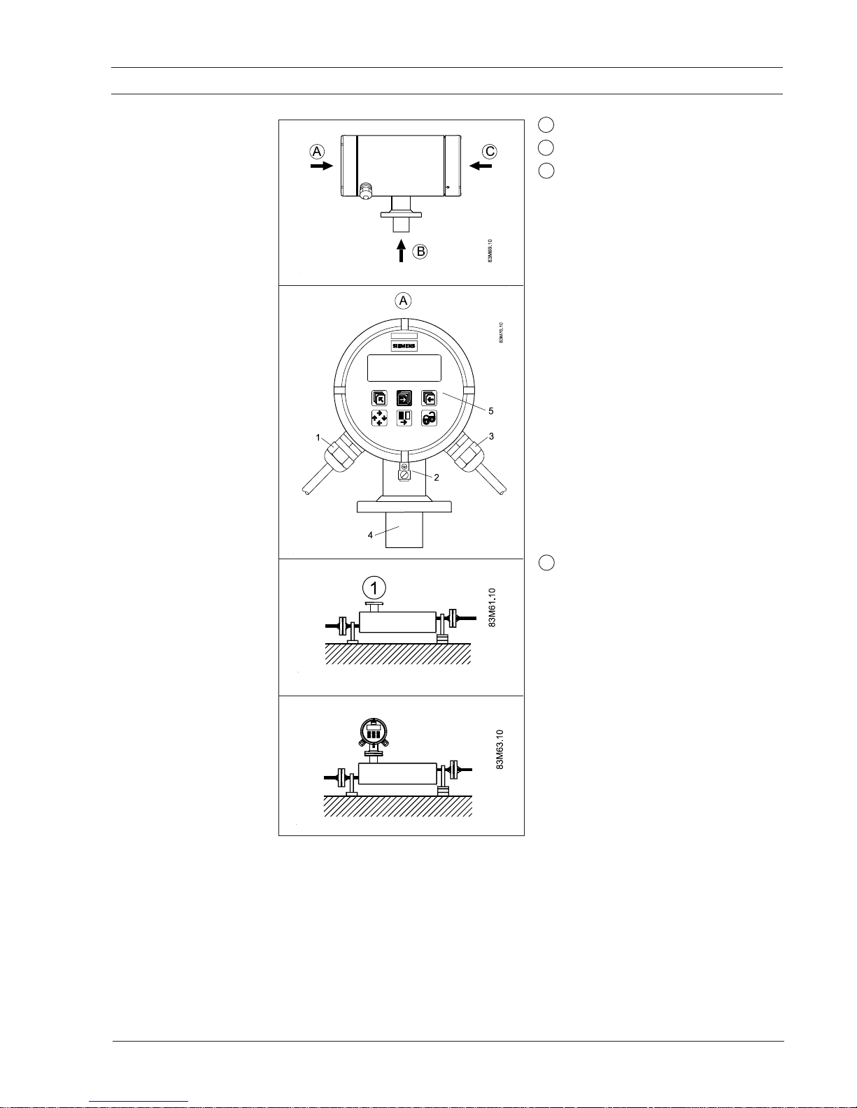
2.4 Overview A = EEx e (Increased safety)
B = EEx ia (Intrinsic safety)
C = EEx d (Flameproof safety)
MASS 6000 Ex-d
Flameproof enlosure
EEx de [ia/ib] IIC T6
1. M20, black ATEX approved glands, power
supply cable.
2. Earthing terminal, connect to potential
equialising coils (PEC).
3. M20, blue ATEX approved glands, output
and input cable.
4. Multi-plug connection to sensor EEx ia.
5. Display with push buttons.
MASS 2100
Intrinsic safety
EEx ia IIC T3...T6
1 Sensor multi-plug connection EEx ia.
MASS 6000 Ex-d and
MASS 2100 compact
EEx de [ia/ib] IIC T3...T6
SITRANS F C MASSFLO
6
SFIDK.PS.028.Q1.02
2. Installation
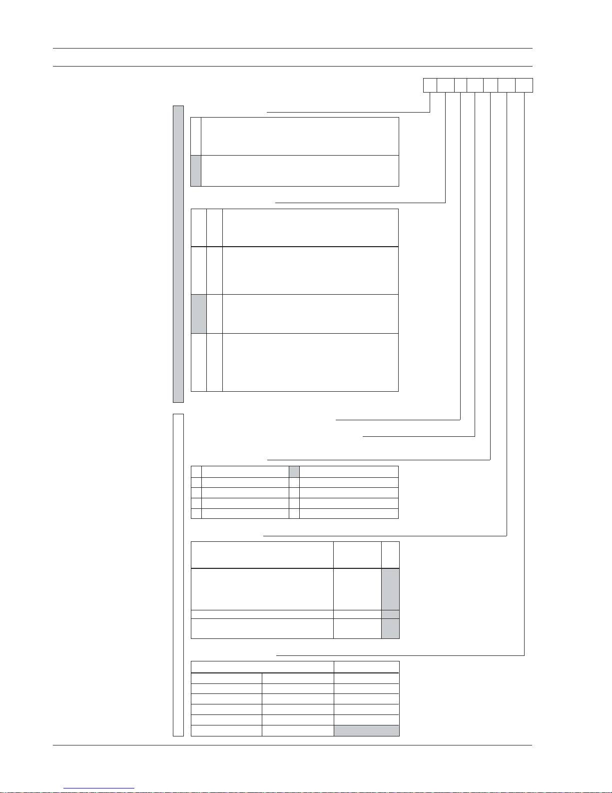
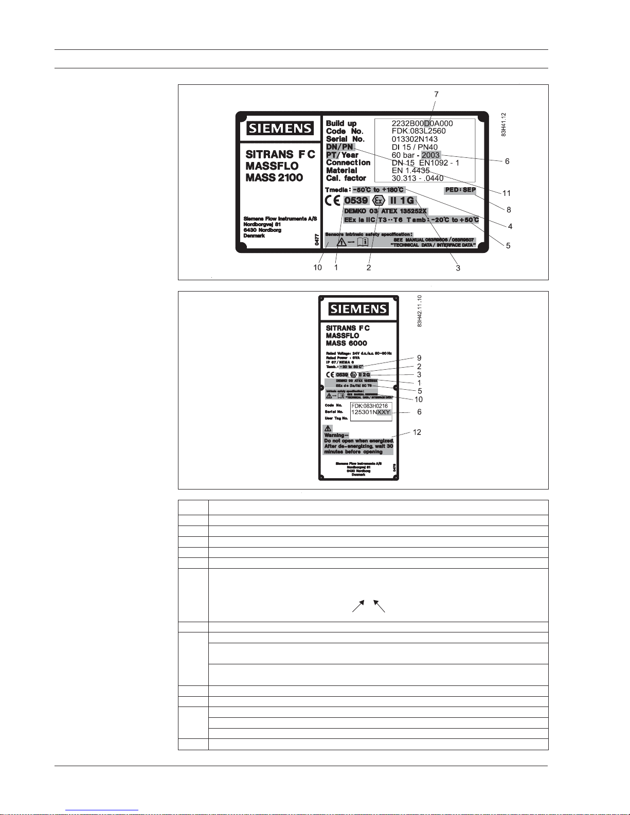
2.5 Device identification
Sensor MASS 2100 label
Signal converter
MASS 6000 Ex-d label
No. Meaning
1. Notified body for QA supervision: UL International DEMKO A/S, Denmark
2. Explosion protected
3. ATEX Equipment Group and Protection Category
4. Maximum medium temperature
5. EC Approval Numbers and Protection Type
6. Production year
Production date:
XX = week, Y = year
Example:
013302N14 3
Week 14 Year 2003
7. Build-up code, "1" = MASS 2100 sensor
8. PED = Pressure Equipment Directive 97/23/EC
PED: SEP marking indicating that the sensor is produced in accordance with
"Sound Engineering Practice"
CE 0200 EN 13480 - category II marking indicating that the sensor conforms to PEDcategory II
9. Ambient temperature range
10. Interface data
11. DN = sensor size
PN = max. pressure
PT = test pressure, sensor pressure tested with 1.5 x PN
12. Warning, do not open the Ex-d enclosure when energized

SITRANS F C MASSFLO
7
SFIDK.PS.028.Q1.02
2.6 Approvals
2.7 Special conditions
for safe use of
MASS 6000 Ex-d
version and MASS
2100
• The sensor type MASS 2100 can be mounted directly onto the plug or separately with special
kit for separate mounting.
• When measuring liquids with higher temperatures than 50°C, the sensor must be insulated.
• The 24 V input voltage shall be from a safety-isolated transformer according to EN 60742 or
EN 61558-1. The input terminals must be certified according to EN 50019 and the maximum
wire size is 1.5 mm
2
.
• The evaluation of the flameproof part of the enclosure is covered by DEMKO certificate
99E.125730U and shall be maintained as a part of this certification.
• All the wiring for increased safety must be located in the separate part of the terminal house
room and must be covered with the plastic cover. The cover is marked „Increased Safety“.
• The signal converter must always be connected to ground using the internal terminal or
external PE ground.
Notified body
2. Installation
Sensor MASS 2100 DI 1.5, DI 3, DI 6, DI 15, DI 25 and DI 40
0539 II 1 G
DEMKO 03 ATEX 135252X
EEx ia IIC T3...T6
Temperature classes for ambient temperature between
−−
−−
−20
°°
°°
°C to +50
°°
°°
°C:
T3 (max. surface < 200°C) for liquid temperature lower than 180°C
T4 (max. surface < 135°C) for liquid temperature lower than 135°C
T5 (max. surface < 100°C) for liquid temperature lower than 100°C
T6 (max. surface < 85°C) for liquid temperature lower than 85°C
Signal converter MASS 6000 Ex-d compact or remote mounted
0539 II 2 G
DEMKO 03 ATEX 135253X
EEx de [ia/ib] IIC T6
ambient temperature −20 to +50°C
The SITRANS F C MASSFLO
mass flowmeter was tested for approval by:
UL International DEMKO A/S
Lyskaer 8, P.O. Box 514
DK-2730 Herlev
Denmark
SITRANS F C MASSFLO
8
SFIDK.PS.028.Q1.02
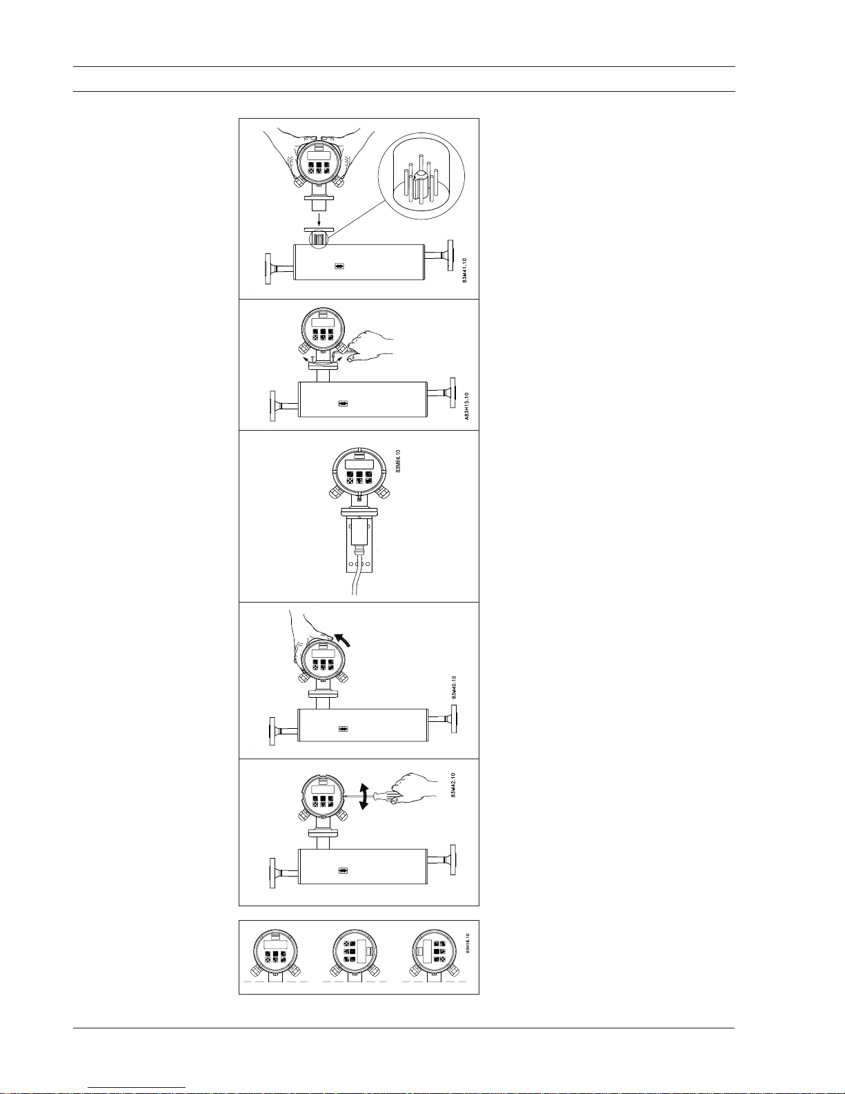
The display/keypad can be rotated in steps of
90°. Please note the little tap on the back of the
display frame which must correspond to the
nut at the converter body when the display/
keypad is replaced. This is essential for obtaining optimum sealing.
2.8 Mounting of signal
converter compact or
remote
Compact Ex-d version
For compact installation mount the converter
on top of the sensor interface. Please make
sure that it is correctly oriented (note the little
tap).
After fitting it can be turned 0-360°.
The converter is fastened with 4 allen screws
(Allen key M4).
Remote Ex-d version
For mechanical mounting refer to instruction
DKFD.PI.028.T1.52 supplied with the mounting kit.
The terminals for inputs, outputs and power
supply can be accessed by removing the front
cover, turning it counter-clockwise.
The display can be lifted off (i.e. with the tip of a
screwdriver or similar) and the terminals are
accessible.
2.9 Display and keypad
2. Installation
SITRANS F C MASSFLO
9
SFIDK.PS.028.Q1.02
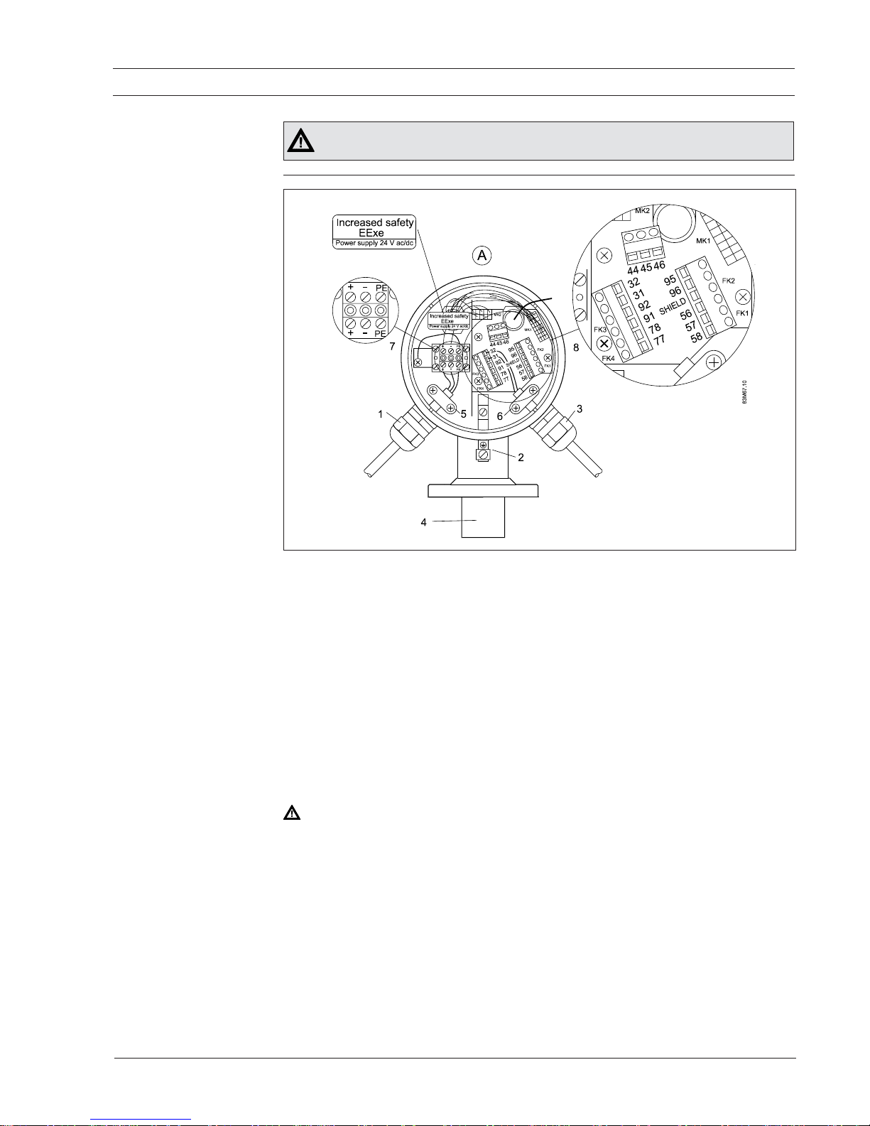
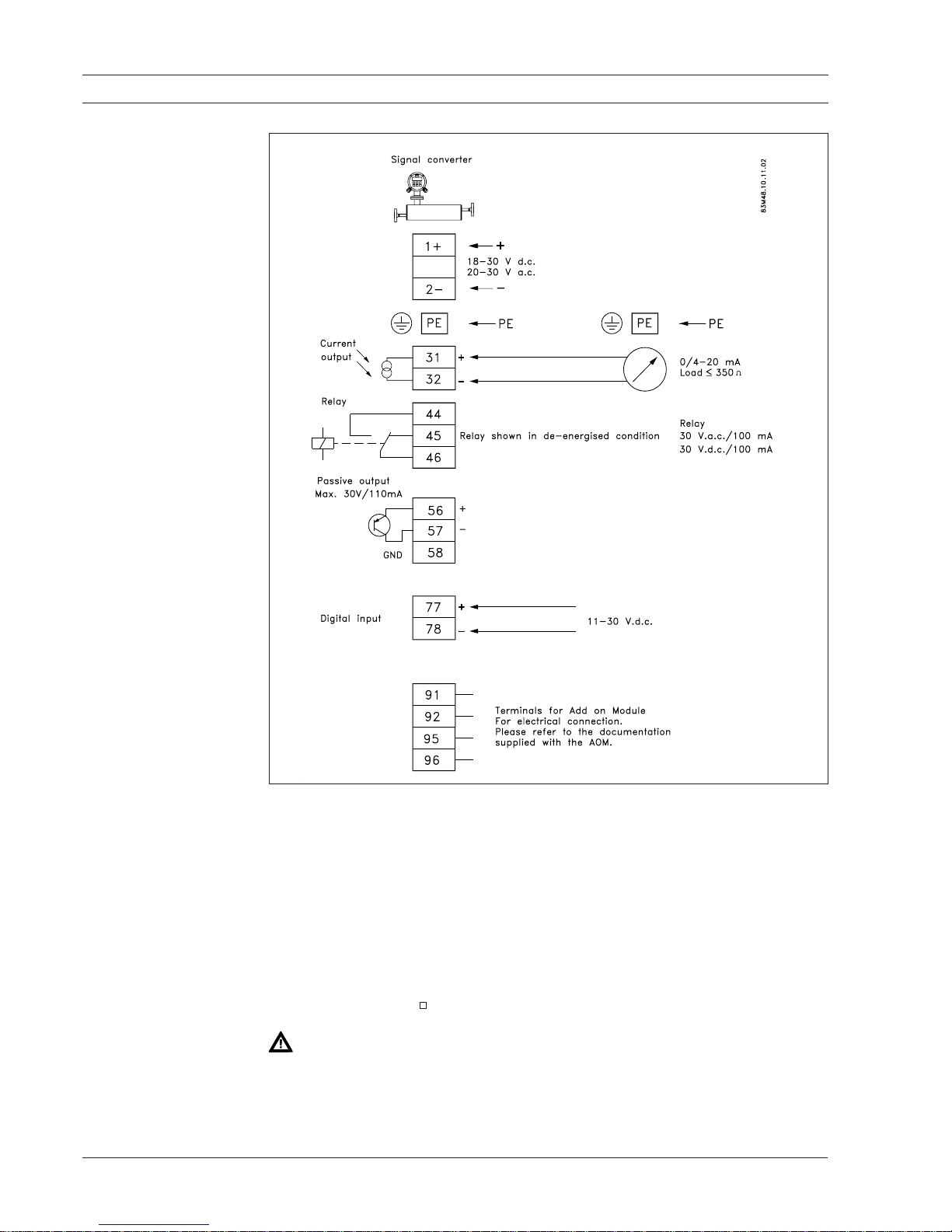
3. Electrical connection
Turn off the power supply before connecting input and output cables and wait 30
minutes before unscrewing the lid.
3.1 Electrical connection
compact or remote
Mounting and connection
View A
EEx e
1. M20 black ATEX approved gland, power supply cable "e".
2. Earthing terminal connected to potential equalisation rails (PEC).
3. M20, blue ATEX approved gland, input and output cable "ia".
4. Multi-plug connection to sensor EEx ia.
5.-6. The power supply and input and output cables must be secured by i.e. cable strap so that
they remain in position even if the cable terminal screws get loose.
7. Power supply terminals, EEx e maximal core cable 1.5 mm
2
.
Tighten the screws with 0.5 – 0.6 Nm!
Mount the plastic cover, marked "Increased safety" again.
8. Input and output terminals EEx ia.
It is an absolute requirement that the wires/terminals of the intrinsically safe circuits cannot get
into contact with the wires of the other cables. The distance between cables/wires therefore must
be at least 50 mm.
It is recommended to fasten the cables/wires in a way that they, even in case of an error, cannot
get into contact with each other. Make the wire ends as short as possible.
Intrinsically safe terminals "ia"!
SITRANS F C MASSFLO
10
SFIDK.PS.028.Q1.02
3. Electrical connection
3.1 Electrical connection
compact or remote
(continued)
Electrical connections are made through the front of the signal converter (view A), in the terminal
housing. This housing is accessed by removing the front cover described in chapter 2.
Read the chapter 4. "Technical data" before making the connection.
The cover is retained via a wire. The terminal housing is equipped with 1 M20 EEx e gland and 1
M20 EEX i gland.
The mains cable is fed through the black PG gland (black indicates increased safety "e") located
in the left-hand side as viewed from the front.
The outputs are fed through the blue PG gland (the colour blue indicates intrinsically-safe circuit "i")
located on the right-hand side. According to the Ex document issued, use of other glands is
permitted provided that these are as a minimum EEx-approved in category "e".
Important
The power supply terminals shall be from a safety isolating transformer.
Maximal cable core is 1.5 .
Turn off the power supply before connecting input and output cables and wait 30 minutes
before unscrewing the lid.
 Loading...